Electrical control over perpendicular magnetization switching driven by spin-orbit torques
Abstract
Flexible control of magnetization switching by electrical manners is crucial for applications of spin-orbitronics. Besides of a switching current that is parallel to an applied field, a bias current that is normal to the switching current is introduced to tune the magnitude of effective damping-like and field-like torques and further to electrically control magnetization switching. Symmetrical and asymmetrical control over the critical switching current by the bias current with opposite polarities is both realized in Pt/Co/MgO and -Ta/CoFeB/MgO systems, respectively. This research not only identifies the influences of field-like and damping-like torques on switching process but also demonstrates an electrical method to control it.
pacs:
I INTRODUCTION
Spin-orbitronicsKuschel and Reiss (2014); Manchon (2014), aiming at current or voltage control of magnetization (M) via spin-orbit coupling (SOC) effect, has gradually manifested itself charming prospect in nonvolatile magnetic storage and programmable spin-logic applications. Spin Hall effect (SHE) in heavy metalsD’Yakonov and Perel’ (1971); Hirsch (1999); Zhang (2000); Sinova et al. (2015) or topologic insulatorsFan et al. (2014a) and Rashba effectBychkov and Rashba (1984); Miron et al. (2010) at the heavy metal/ferromagnetic metal interfaces are two broadly utilized effects to realize spin-orbitronics due to their large SOC strength. With the aid of magnetic field, SHE induced magnetization switching has already been realized in many systems comprising a magnetic layer (Co, CoFeB, NiFe) sandwiched by an oxide layer(AlO, MgO) and a heavy metal layer (Pt, -Ta, W) with not only in-plane anisotropyFan et al. (2013); Liu et al. (2012a) but perpendicular anisotropyMiron et al. (2011); Liu et al. (2012b); Pai et al. (2012); Qiu et al. (2015). Recently, field-free magnetization switching via current has been also achieved in a wedged Ta/CoFeB/TaOYu et al. (2014) or antiferromagnetic/ferromagnetic coupled perpendicular systemsFukami et al. (2016); van den Brink et al. (2016); Lau et al. (2015).
In those perpendicular systems, current can generate via SHE effect a damping-like torque which balances effective torques from perpendicular anisotropy and in-plane bias field and consequently switches magnetization as it becomes large enough. In these previous researches, mainly spin Hall torque (along x axis) induced by one current (namely, switching current I along y axis) applied along the direction of an applied or effective magnetic field is taken into account while the influence of field-like torque (along y axis) on magnetic reversal process is rarely experimentally testified. Definition of coordinates is shown in Fig. 1(a).
Here, we introduced another current (namely, bias current along x axis) to electrically control magnetization switching process (Fig. 1(a)). The damping-like and field-like torques of the bias current have the same symmetry with the field-like and damping-like torque of the switching current, respectively. Therefore, as shown below, the influences of both field-like torque and damping-like torque of the switching current on magnetization switching process become visible with tuning the magnitude of the bias current. Furthermore, the main features of aforementioned results can be well reproduced by a macrospin model which provides further understanding. This work can not only help to distill the influences of different kinds of torques on the switching process but also demonstrate a practical manner of controlling SHE-driven magnetization switching process by electrically tuning the magnitude of effective damping-like and field-like torques.
II EXPERIMENTAIL METHOD
SiO2//Ta(5)/Co20Fe60B20(1)/MgO(2)/Pt(3) and SiO2//Pt(5)/Co(0.8)/MgO(2)/Pt(3) (thickness in nanometer) stacks were provided by Singulus GmbH. They were magnetron-sputtered at room temperature. They have intrinsically in-plane anisotropy. After annealing at 400 and 10-3 Pa for 1 h in a perpendicular field of 0.7 T could the stacks exhibit strong PMA. Raw films were then patterned by ultraviolet lithography and the following two-step argon ion etching into Hall bars with the size of the center squares being 20 m (Fig. 1(a)). Cu(10 nm)/Au(30 nm) electrodes were finally deposited to make contacts with four legs of Hall bars. After device microfabrication, the Hall bars were measured with two Keithley 2400 sourcemeters and Keithley 2182 voltmeter sourcing devices and measuring Hall voltages, respectively. Meanwhile, PPMS-9T (Quantum Design) provided magnetic fields with proper directions. The two Keithley 2400 sourcemeters first provided the current pulses to the Hall bar. One applied switching current along the y axis and the other applied bias current along the x axis to the sample with a duration time of 50 ms. Then the two Keithley 2400 stopped sourcing after the duration time. After waiting for 100 ms, one Keithley 2400 applied another current pulse of 1 mA along the y axis to the sample for 100 ms. At the end of this pulse, Keithley 2182 picked up the Hall voltage along the x axis. Then the Keithley 2400 was switched off. After 100 ms, the next round of destabilizing-measuring process was performed.
III RESSULTS AND DISCUSSION
III.1 Experiment
Two typical perpendicular systems Sub//Pt(5)/Co(0.8)/MgO(2)/Pt(3) (PCM for short) and Sub//Ta(5)/Co20Fe60B20(1.0)/MgO(2)/Pt(3) (TFM) are used for comparison. Thickness is in nanometers. Here Ta is in -phase instead of -phase (Fig. 1(b)). The strong peak at 2=55.6∘ can be only ascribed to (200) plane of -Ta. Absence of the two main peaks at 2=63.6∘ and 64.7∘ corresponding to (631) and (413) planes of -phase, respectively, indicates nonexistence of -phase. The wide peak at 2=39∘ can be attributed to the merge of (110) plane of -Ta and (111) plane of Pt. The other wide peak at 2=68∘ can be due to the merge of (211) plane of -Ta and (220) plane of Pt.
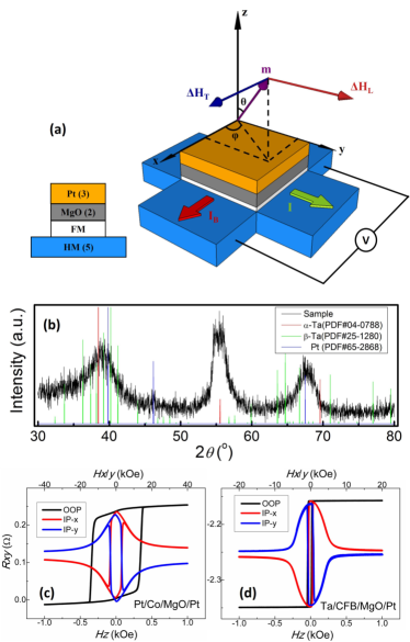
of PCM and TFM measured by Vibration Sample Magnetometry is 125 emu/cm2 and 145 emu/cm2, respectively. and is saturated magnetization and thickness of magnetic layer, respectively. Hall measurement demonstrates perpendicular magnetic anisotropy (PMA) of both systems. PCM shows higher PMA energy than TFM. Anisotropy field () of PCM and TFM is about 13.6 kOe and 5.8 kOe, respectively (Figs. 1(c) and 1(d)). Sophisticated harmonic lock-in techniquePi et al. (2010); Kim et al. (2012) is applied here to characterize spin-orbit torques of the above systems induced by applied current. The effective longitudinal field and effective transverse field corresponding to damping-like torque and field-like torque, respectively, are shown in Fig. 1. Sample structure is also shown (Fig. 1(a)).
During measurement, current density (=) is applied along +y axis. Magnetic field (H) is applied along x or y axis. Direction of H determines which torque can be detected. and are respectively used to measure current-induced field-like torque (or effective transverse field corresponding to the field-like torque) and damping-like torque (or effective longitudinal field corresponding to the damping-like torque). First and second harmonic Hall voltages along x axis (= and =) are picked up to indirectly show direction of magnetization (M) respective to the +z axis and -tuned M change, accordingly. and exhibit parabolic and linear field dependence as M around z, respectively. Especially, the vs. H curves (Fig. 2(b)) exhibit the same slopes at as H is along y while they exhibit opposite slopes as H is along x (Fig. 2(d)). From the slopes as well as (Figs. 2(a) and 2(c)) can we obtain along y axis and along x axis via =-2()(). Here H parallel to M originates from spin Hall effect. H parallel to originates from Rashba field as well as Ostered field. The is the spin current density induced by the j via j z.
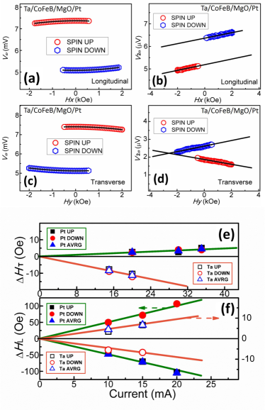
The shows linear dependence on applied current density with zero intercepts as expected. Parameter defined as characterizes conversion efficiency from charge current to effective field. Here, =. I is the switching current, w is the width of Hall bar (20 m) and is the thickness of the heavy metal (5 nm). 1 mA of I thus corresponds to 1 MA/cm2 of . The shielding effect of the ferromagnetic layer and anti-oxidation layer is ignored. Thus, and should be deemed as an upper and lower bound, respectively. The is about -40 nm and +4 nm for PCM and TFM, respectively (Fig. 2(e)). Meanwhile, the is about +1.2 nm and -4 nm for PCM and TFM, respectively (Fig. 2(f)). Especially, of -Ta and Pt has opposite signs. The of Pt is reported in the order of 1 m-1 nmMiron et al. (2010); Fan et al. (2013); Liu et al. (2012b); Pi et al. (2010); Fan et al. (2014b) in different systems. Our value is closer to that of LiuLiu et al. (2012b) and FanFan et al. (2013). Besides, , consistent with the results of LiuLiu et al. (2012b). The of Ta in Ta/CoFeB/MgO system is thoroughly researched by KimKim et al. (2012). It is in the order of 2-20 nm, depending on thickness of Ta and CoFeB. Besides, their results show can be comparable and even larger than . Our measured values are within their range and is equal to . However, the of -Ta is smaller than that of -TaKim et al. (2012). Ratio of / for Pt and -Ta is -0.03 and -1, respectively. Field-like torque can be nearly neglected in the PCM while it cannot be ignored in the TFM, which provides us a couple of ideal systems to research the influence of field-like torque and damping-like torque on switching behavior of perpendicular films. The reason why field-like torque is insignificant and significant in PCM and TFM system respectively, we think, is that the two systems may have different interfacial potentials due to different work functions of Pt (5.3 eV), Co (4.4 eV), Fe (4.3 eV), and Ta (4.1 eV)Michaelson (1977); Skriver and Rosengaard (1992) as elaborated in Ref. [Barnes et al., 2014].
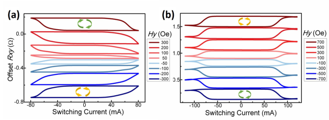
In the following, we will use the PCM with /=-0.03 and the TFM with /=-1 to study the influence of on switching behaviors and introduce the underneath mechanism based on a macrospin model. I and are applied along y. is applied along x. As =0, M can be switched back and forth between spin-up state and spin-down state (Fig. 3) by scanning I under nonzero . Due to opposite spin Hall angle, switching direction is opposite for PCM and TFM with the same measurement setup. For example, switching direction for TFM and PCM is clockwise and anticlockwise, respectively, at positive . Sign reversal of leads to reversal of the switching direction. Fig. 3 also shows nearly a full magnetization switching can be realized as =0.3 kOe for TFM. In this condition, critical switching current () is 63.5 mA. Meanwhile, the for PCM is about 80 mA as =0.7 kOe. These results manifest -Ta can also function as a high efficient converter from charge current to spin current besides of Pt and -Ta.
As shown in Figs. 4(a) and 4(b) elevated can significantly reduce the in the PCM system. For example, =88 mA as =0 mA while =73 mA as =50 mA. decreases by 17%. Meanwhile, positive and negative leads to nearly the same amount of reduction, no matter the sign of as shown by the parabolic fitting lines in Figs. 4(c) and 4(d). This -induced decrease in can be ascribed to the damping-like torque from as shown in the theoretical part below. It is worthy of accentuating that the damping-like torque of shares the similar symmetry with the field-like torque of I and thus a large field-like torque of I could also in principle reduce the .
Certainly, will heat magnetic films as well and in principle reduce the effective , which could also reduce . However, our experiment shows that varies little as changing duration time of from 50 ms to 1 s, which indicates that thermal effect is at least not dominating factor in determining here.
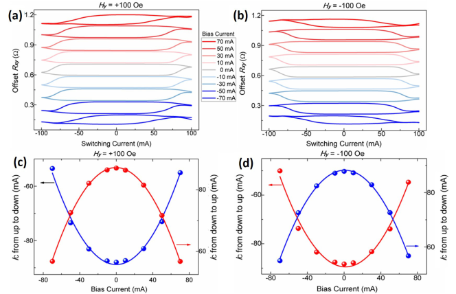
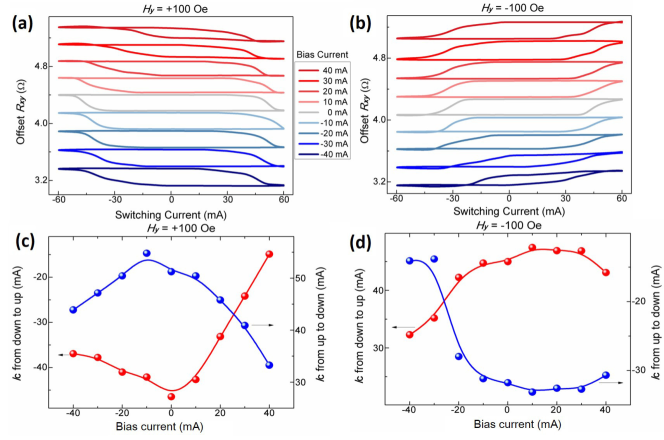
On the other hand, TFM system manifests a different response to with different symmetry in comparison with the PCM counterpart. As shown in Figs. 5(a) and 5(c) for =+100 Oe and the transition from down-state to up-state, is reduced by about 67% under =40 mA while it is only reduced by 20% under =-40 mA. In contrast, for =-100 Oe and the transition from up-state to down-state (Figs. 5(b) and 5(d)), besides of the opposite switching direction, the effect of on is also reversed, i.e. decreased only by about 5% under =40 mA while it decreased remarkably by 53% under =-40 mA. Here, the asymmetric response of to positive and negative cannot be interpreted by damping-like torque induced by or heating effect as shown in the case of PCM. Instead, field-like torque of is a key contributor to the asymmetry as shown below.
III.2 Macrospin model
In order to interpret the different response of PCM and TFM to , we have turned to a macrospin model (more details in Appendix). The magnetic energy includes uniaxial anisotropy energy and Zeeman energy where and is the polar angle between M and the +z axis and the azimuthal angle between in-plane projection of M and the +x axis, respectively (Fig. 1(a)). I and provide both a damping-like torque and a field-like torque on M with efficiency characterized by /. We use parameter a in unit of to denote the damping-like torque provided by I, parameter c to denote the ratio of and parameter b to denote the ratio of /. Actually, c reflects the angle of total current density with respect to the direction of magnetic field. As I and are both applied, torque equilibrium condition requires satisfaction of Eq. (1).
| (1) | ||||
Here H=E, mM/, , e and e is a unit vector along the x and y axes, respectively. The 2 and 3 term in the RHS of Equation (1) is damping-like and field-like torque from I while the 4 and 5 term is damping-like and field-like torque from , respectively. Equation (1) can be further reduced as scalar equations. Equation (2) is one of them.
| (2) |
If =0 and b=0, , which shares the similar form as derived by LiuLiu et al. (2012b) and YanYan and Bazaliy (2015). Here . Comparing Eq. (2) with the simplified one as =0 and b=0, we can see that introduction of leads to an effective and an effective damping-like torque as expressed in Equation (3).
| (3a) | |||
| (3b) |
Simulated results according to Eq. (1) are shown in Fig. 6 where is the critical damping-like torque of I. As c=0, a nonzero b can significantly reduce critical switching current (), regardless of its sign (Fig. 6(g)). decreases by 5.8% and 42% as b=1 and b=3.6Kim et al. (2012), respectively, compared with the as b=0. This trend is consistent with the result in the PCM sample in which the damping-like torque of can mimic the influence of the field-like torque of I. Though it cannot reverse M directly, large Rashba effect can still help to effectively reduce .
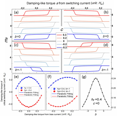
As b=0, bias current (c0) can notably decrease and the amount of the reduction in does not depend on polarity of c (Figs. 6(a) and 6(b)), which manifests similar characteristics with the switching behaviors of the PCM sample. As b=-1 and =0.4 (Fig. 6(c)), c=0.3 and c=-0.3 will result in asymmetric decrease in . Here c=-0.3 is more effective in reducing . However, as =-0.4 (Fig. 6(d)), reduces more in the case of c=+0.3. These characteristics (Figs. 6(c) and 6(d)) well reproduce the results of the TFM sample in Figs. 5(a) and 5(b). Figs. 6(e) and 6(f) shows the dependence of as b=0 and b=-1, respectively. The former indeed predicts a parabolic dependence as observed in Figs. 4(c) and 4(d) while the latter also predicts a linear dependence besides of the parabolic one, which qualitatively reproduces the results in Figs. 5(c) and 5(d). It is worth bearing that field-like torque and damping-like torque are both indispensable to realize the asymmetry reduction of under opposite . Fig. 5 also indirectly manifests that the two types of torque both play important roles in magnetization switching process of the TFM system.
Other Pt/Co/MgO and Ta/CoFeB/MgO samples have exhibited similar switching symmetries. Noteworthy, though we demonstrate the switching behaviors with aid of an applied field, the switching performance controlled by will be still achievable in principle if the applied field is replaced by an effective field from exchange coupling.
IV SUMMARY
Current induced torques of Pt and -Ta, including damping-like torque and field-like torque, have been characterized by second-harmonic technique as =-40 nm, =+4 nm, =+1.2 nm and =-4 nm. Current can generate much larger field-like torque in -Ta than in Pt. Current-induced magnetization switching has also been realized in the -Ta system, indicating its high enough spin-orbit coupling strength and shedding light on its potential use in spin-orbitronics. Field-like torque, though incapable of switching M directly in our case, plays crucial role in reducing .
results in different influences on switching behaviors for the TFM and PCM systems. Opposite equally decreases in PCM while it asymmetrically influences the in TFM system. Furthermore this asymmetry originates from the field-like torque of and can be adjusted by polarity of . Our work not only brings to light the influence of damping-like and field-like torques of switching current and bias current on switching but also experimentally demonstrates an electrical manner (via bias current) to symmetrically or asymmetrically control the switching, which could advance the development of spin-logic applications in which control of the switching process via electrical methods is crucial and beneficial.
Acknowledgements.
This work was supported by the 863 Plan Project of Ministry of Science and Technology (MOST) (Grant No. 2014AA032904), the MOST National Key Scientific Instrument and Equipment Development Projects [Grant No. 2011YQ120053], the National Natural Science Foundation of China (NSFC) [Grant No. 11434014, 51229101, 11404382] and the Strategic Priority Research Program (B) of the Chinese Academy of Sciences (CAS) [Grant No. XDB07030200].*
Appendix A DETAILS OF MACROSPIN MODEL
The schematic structure of the Pt/Co/MgO or Ta/CoFeB/MgO is shown in Fig. 1(a). An applied field and the switching current (I) are along the +y axis. The bias current () is along the +x axis. The ratio of /I is defined as a parameter c which actually reflects the angle between the direction of total current density with that of the applied field. Easy axis of the perpendicular systems (PCM or TFM) is along the z axis. Therefore the total energy (E) is with K anisotropy energy, saturation magnetization and permeability of vacuum. This energy drives an effective field H=E. Here we use a macrospin model for simplicity and therefore only and are variable with the being a constant. = and =. . and are two orthogonal components of H. As the currents I and are both applied, magnetization direction will be modulated due to the damping-like and field-like torques originated from the I and . The damping-like torque of a unit of M induced by the I via spin Hall effect is defined as a parameter a which is proportional to the spin Hall angle and along the x axis. Then the damping-like torque induced by the is ac which is however along the y axis. As shown in the maintext, is defined as the effective field correspond to the damping (field)-like torque induced by an unit of I. Here we further define b as /. Thus field-like torque induced by the I via Rashba effect as well as Ostered mechanism is ab and along the y axis. In contrast, the field-like torque induced by the is abc and along the x axis. It is very important that the direction of the field-like torque induced by the I is the same as that of the damping-like torque induced by the . They are both along the y axis. The final state of the system is determined by the following LLG equation (4).
| (4) | ||||
In the first line of Equation (4), and are gyromagnetic ratio and damping constant, respectively. The quantity e and e is unit vector along the x and y axis, respectively. The 1 and 2 term in the second line is damping-like and field-like torque induced by the switching current (I), respectively. The 1 and 2 term in the third line is damping-like and field-like torque induced by the bias current (), respectively. At the steady state, M=. Thus we arrive at Equation (5).
| (5) | ||||
Here we have replaced M/ with m. Equation (5) gives the scalar equations (6) which is also shown in the main text.
| (6a) | |||
| (6b) |
As c=b=0, Equation (6) is reduced as Equation (7)
| (7a) | |||
| (7b) |
One possible solution as well as the final physically meaningful solution of Equation (7) is further reduced as Equation (8)
| (8a) | |||
| (8b) |
This solution shares the similar form with that derived in Ref.[Liu et al., 2012b], which demonstrates the rationality of our derivations.
In general case, Equation (6) can be transformed as Equation (9).
| (9a) | |||
| (9b) |
Comparing Equation (8b) and (9b), we find that the introduction of actually updates the with an effective field of and updates the a with an effective torque of .
As c=0, the effective field becomes . A nonzero b can make the effective field larger, which is very beneficial for higher efficient switching. As b=0, the effective field becomes . Therefore, the introduction of the bias current (or nonzero c regardless of its polarity) can also increase the effective field. Besides, the field-like torque of the switching current (ab) in the former case functions a similar role with the damping-like torque of the bias current (ac) in the latter case. Only as b0 can c with opposite sign asymmetrically influence the effective field. It is also worth noting that the is still indispensable for magnetization switching because a zero will also lead to a zero effective torque. The numerical results regarding the solutions of Equation (6) are shown in the Fig. 6 in the main text and not shown here.
References
- Kuschel and Reiss (2014) T. Kuschel and G. Reiss, Nature Nanotech 10, 22 (2014).
- Manchon (2014) A. Manchon, Nat Phys 10, 340 (2014).
- D’Yakonov and Perel’ (1971) M. I. D’Yakonov and V. I. Perel’, JETP Letters 13, 467 (1971).
- Hirsch (1999) J. E. Hirsch, Phys. Rev. Lett. 83, 1834 (1999).
- Zhang (2000) S. Zhang, Phys. Rev. Lett. 85, 393 (2000).
- Sinova et al. (2015) J. Sinova, S. O. Valenzuela, J. Wunderlich, C. H. Back, and T. Jungwirth, Rev. Mod. Phys. 87, 1213 (2015).
- Fan et al. (2014a) Y. Fan, P. Upadhyaya, X. Kou, M. Lang, S. Takei, Z. Wang, J. Tang, L. He, L.-T. Chang, M. Montazeri, G. Yu, W. Jiang, T. Nie, R. N. Schwartz, Y. Tserkovnyak, and K. L. Wang, Nature Materials 13, 699 (2014a).
- Bychkov and Rashba (1984) Y. A. Bychkov and E. I. Rashba, JETP Letters 39, 66 (1984).
- Miron et al. (2010) I. M. Miron, G. Gaudin, S. Auffret, B. Rodmacq, A. Schuhl, S. Pizzini, J. Vogel, and P. Gambardella, Nature Materials (2010).
- Fan et al. (2013) X. Fan, J. Wu, Y. Chen, M. J. Jerry, H. Zhang, and J. Q. Xiao, Nature Communications 4, 1799 (2013).
- Liu et al. (2012a) L. Liu, C.-F. Pai, Y. Li, H. W. Tseng, D. C. Ralph, and R. A. Buhrman, Science 336, 555 (2012a).
- Miron et al. (2011) I. M. Miron, K. Garello, G. Gaudin, P.-J. Zermatten, M. V. Costache, S. Auffret, S. Bandiera, B. Rodmacq, A. Schuhl, and P. Gambardella, Nature (London) 476, 189 (2011).
- Liu et al. (2012b) L. Liu, O. J. Lee, T. J. Gudmundsen, D. C. Ralph, and R. A. Buhrman, Phys. Rev. Lett. 109 (2012b).
- Pai et al. (2012) C.-F. Pai, L. Liu, Y. Li, H. W. Tseng, D. C. Ralph, and R. A. Buhrman, Appl. Phys. Lett. 101, 122404 (2012).
- Qiu et al. (2015) X. Qiu, K. Narayanapillai, Y. Wu, P. Deorani, D.-H. Yang, W.-S. Noh, J.-H. Park, K.-J. Lee, H.-W. Lee, and H. Yang, Nature Nanotech 10, 333 (2015).
- Yu et al. (2014) G. Yu, P. Upadhyaya, Y. Fan, J. G. Alzate, W. Jiang, K. L. Wong, S. Takei, S. A. Bender, L.-T. Chang, Y. Jiang, M. Lang, J. Tang, Y. Wang, Y. Tserkovnyak, P. K. Amiri, and K. L. Wang, Nature Nanotech 9, 548 (2014).
- Fukami et al. (2016) S. Fukami, C. Zhang, S. DuttaGupta, A. Kurenkov, and H. Ohno, Nature Materials 15, 535 (2016).
- van den Brink et al. (2016) A. van den Brink, G. Vermijs, A. Solignac, J. Koo, J. T. Kohlhepp, H. J. M. Swagten, and B. Koopmans, Nature Communications 7, 10854 (2016).
- Lau et al. (2015) Y.-C. Lau, D. Betto, K. Rode, J. Coey, and P. Stamenov, (2015), arXiv:1511.05773 .
- Pi et al. (2010) U. H. Pi, K. W. Kim, J. Y. Bae, S. C. Lee, Y. J. Cho, K. S. Kim, and S. Seo, Appl. Phys. Lett. 97, 162507 (2010).
- Kim et al. (2012) J. Kim, J. Sinha, M. Hayashi, M. Yamanouchi, S. Fukami, T. Suzuki, S. Mitani, and H. Ohno, Nature Materials 12, 240 (2012).
- Fan et al. (2014b) X. Fan, H. Celik, J. Wu, C. Ni, K.-J. Lee, V. O. Lorenz, and J. Q. Xiao, Nature Communications 5 (2014b).
- Michaelson (1977) H. B. Michaelson, J. Appl. Phys. 48, 4729 (1977).
- Skriver and Rosengaard (1992) H. L. Skriver and N. M. Rosengaard, Phys. Rev. B 46, 7157 (1992).
- Barnes et al. (2014) S. E. Barnes, J. Ieda, and S. Maekawa, Sci. Rep. 4 (2014).
- Yan and Bazaliy (2015) S. Yan and Y. B. Bazaliy, Phys. Rev. B 91 (2015).