From cylindrical to stretching ridges and wrinkles in twisted ribbons
Abstract
Twisted ribbons subjected to a tension exhibit a remarkably rich morphology, from smooth and wrinkled helicoids, to cylindrical or faceted patterns. These shapes are intimately related to the instability of the natural, helicoidal symmetry of the system, which generates both longitudinal and transverse stresses, thereby leading to buckling of the ribbon. In this paper, we focus on the tessellation patterns made of triangular facets. Our experimental observations are described within an “asymptotic isometry” approach that brings together geometry and elasticity. The geometry consists of parametrized families of surfaces, isometric to the undeformed ribbon in the singular limit of vanishing thickness and tensile load. The energy, whose minimization selects the favored structure among those families, is governed by the tensile work and bending cost of the pattern. This framework describes the coexistence lines in a morphological phase diagram, and determines the domain of existence of faceted structures.
Sheets subjected to external forces store the exerted work in local or global elastic deformations that underlie wrinkled and crumpled states. For tensile loads, the exerted work is typically stored as pure stretching energy. When the forces are compressive, the strain is negligible and the exerted work is instead stored as bending energy. For instance, a sheet resting on a soft substrate and compressed uniaxially deforms isometrically into wrinkles or folds pocivavsek_08 ; brau11 . However, when the compressive forces result from geometrical constraints, the final shape may involve a complex combination of bending and stretching energies. For instance, a complex 3D shape made by confining a thin sheet, such as a crumpled paper ball, is often described as an assembly of flat polygonal facets delimitated by ridges where stretching and bending predominate witten_07 . Such a faceted morphology is an efficient minimizer of stretching since it is isometric to the undeformed sheet (i.e. it is strainless) everywhere except at those narrow ridges, reaching a perfect isometry only at the singular limit of vanishing thickness.
Two types of ridges have been reported: i) isometric (cylindrical) ridges, which involve only bending, and ii) stretching ridges, in which the bending and stretching energies are comparable, leading to a width , where is the length of the ridge and is the thickness of the sheet witten_07 ; audoly_10 . Transitions from isometric to stretching ridges were reported for very simple geometries. Witten showed that a single stretching ridge becomes isometric when both ends are truncated witten_09 , and Fuentealba et al. have studied a tearing flap subjected to a pulling force and found a transition from isometric to stretching ridge when the pulling force exceeds a threshold (where is the bending modulus and the Young’s modulus of the sheet) fuentealba_15 . Both studies suggest that the curvature imposed at the end of the ridge completely determines its shape.
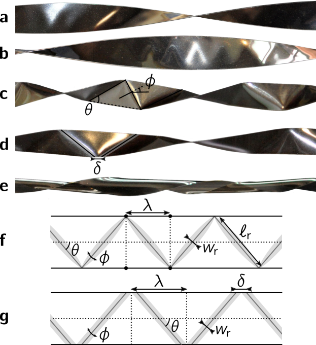
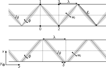
In this letter, we investigate transitions between isometric and stretching ridges in the complex morphology of a twisted ribbon, and characterize their impact on their mechanics. The classical set-up of a twisted ribbon whose short edges are held apart by a small tensile force was first studied by Green green_36 ; green_37 . It was recently revisited by Chopin and Kudrolli chopin_13 , who proposed to organize the observed morphologies in a tension-twist phase diagram. The helicoid (Fig. 1a), characterized by a stretching of the edges as well as the midline, appears usually for moderate twist angles and large tensions. Increasing the twist at moderate tension, the helicoid undergoes a buckling instability, whereby longitudinal wrinkles also described as a zig-zag fold form around its midline coman_08 (see Fig. 1b).Further increasing the twist leads to a faceted morphology, also called “creased helicoid” chopin_13 or “ribbon crystal” bohr_13 (Figs. 1c and 1d). Additionally, the helicoid buckles in the transverse direction upon increasing the twist at sufficiently large tension chopin_15 , and reaches a cylindrical shape (Fig. 1e). We must clarify here that in the above sentences and throughout this letter we refer to tensile loads as “large”, “moderate”, or “small” according to their ratio with certain powers of the thickness , but even the “large tension” corresponds to characteristic strains of or less, deeply in the Hookean regime of material response. In this sense, the morphological transitions reported in green_36 ; green_37 ; chopin_13 , as well as in this work, are universal and not material-dependent.
The faceted morphology has been described using a purely isometric shape, either by solving effective equations for the midline of the ribbon korte_11 or by assuming that it consists of flat triangular facets separated by isometric ridges bohr_13 . However, facets are observed over a whole region of the twist-tension phase diagram, where the tension is small but nonzero chopin_13 , suggesting that this morphology can accommodate a finite amount of stretching. Furthermore, upon increasing the tension at moderate twist, facets turn into longitudinal wrinkles, which are clearly stretched chopin_13 (see Fig. 1b). Motivated by these observations, we focus here on the faceted morphology: we determine experimentally its domain of existence and propose a theoretical framework to explain how facets separated by isometric ridges (FIR) that are observed at small tension, turn into facets separated by stretching ridges (FSR), and then to longitudinal wrinkles (WH) at large tension.
We use ribbons of length , width , and thickness under external tension and clamped at their short edges, which are twisted relative to each other by a prescribed angle . Our ribbons are composed of polyethylene terephthalate PET (Young modulus ) or softer polydimethyl siloxane PDMS (). For simplicity of the analysis, we assume the Poisson ratio (a analysis has no qualitative implications). We use as a unit of length, and the stretching modulus as a unit of in-plane stress (i.e., ), and introduce the twist per unit ribbon length , and the energy per unit length . The different observed shapes are shown on Fig. 1 and are organized in a phase diagram (Fig. 2), which focuses on the longitudinally buckled morphologies and complements the one reported in chopin_13 .
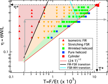
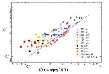
Our experimental “trajectory” is depicted by the gray lines in Fig. 2. To avoid hysteresis, the tension at each segment is either constant or increases. We start at a very small tension and zero twist, and progressively increase the twist. Once the chosen twist angle is attained, the tension is increased progressively. First, the ribbon takes a helicoidal shape (Fig. 1a). As is increased further, such that , the centerline of the helicoid is under compression. A linear stability analysis shows that buckling occurs when , forming first wrinkled helicoids coman_08 ; green_36 ; green_37 ; chopin_13 ; chopin_15 . The prediction for the critical twist is compared to our experimental results in Fig. 3, and shown in the phase diagram Fig. 2 (red line).
Facets separated by isometric ridges (FIR). Increasing the twist beyond the buckling threshold, still at very small tension, we observe a shape resembling facets separated by rounded cylindrical ridges (see Fig. 1d). We follow Ref. bohr_13 and model it with flat triangular facets separated by cylindrical ridges. Such a shape is parametrized by the two angles and , formed, respectively, between the ridges and the ribbon’s midline, and between adjacent facets (Fig. 1c and 1g), and by the radius of curvature of the ridges, . In contrast to Ref. bohr_13 , we find and by energy minimization.
We evaluate the energy using the general framework of asymptotic isometries chopin_15 , which is valid for physically admissible states in the doubly-asymptotic limit of vanishing tension and thickness . The energy of such states can be approximated by the sum of a tensile work and an elastic energy , both of which vanish in the limit :
| (1) |
where the contraction is ( being the end-to-end distance). This formalism allows to compute both and from geometrical and mechanical considerations, yielding expressions that have no explicit dependence on and can be formally evaluated at . We can thus make a tension-independent construction by using parameters with geometrical meaning (), whose actual dependence on is found when minimizing the whole energy, Eq. (1). Notice that the (unwrinkled) helicoid, for instance, is not an asymptotic isometry of the ribbon, since its elastic energy is proportional to and does not vanish as chopin_15 . More generally, in the asymptotic limit , the AI framework is valid only if ratio , between the twisted-induced stress , and the exerted tension , is sufficiently large. We will use this framework not only for the FIR but also for the other shapes obtained upon increasing the tension. A similar approach has been used in other studies of sheets (or shells) on which a Gaussian curvature is imposed in the presence of small tension vella_15 ; vella_15b ; paulsen_15 .
The twist and contraction of a FIR can be obtained from geometrical arguments (see Ref. bohr_13 and SM SM ). Upon expansion for small and , we obtain:
| (2) |
The bending energy of a single ridge is given by (using that SM ). Assuming a small width of the ridge compared to the wavelength , there are ridges per unit ribbon length, and the elastic energy per unit ribbon length becomes
| (3) |
Minimizing the global energy (keeping terms up to the order in the contraction) yields:
| (4) | |||
| (5) |
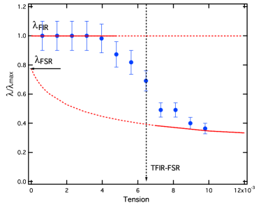
Notably, the independence of the wavelength on tension indicates the robust, geometrical nature of the FIR shape, despite the nontrivial dependence of its energy on the tensile load . In hindsight, this robustness explains the validity of the purely geometric approach of Refs. korte_11 ; bohr_13 for describing the general structure of the FIR. In Fig. 4, we test the prediction by varying the tension at constant . Only the low- regime, where is constant, exhibits the FIR. The independence of on is in agreement with the theory, despite a slight discrepancy between the observed and predicted values of the wavelength that may be attributed to the finite size of the ribbon (). We also note that a similar scaling of with and was obtained in Ref. fuentealba_15 for a completely different system, namely the width of a pulling flap in an isometric configuration. Finally, inspection of Eq. (5) shows that the tensile work and elastic energy are balanced only for . Therefore, for FIR at very small tension (), the work done by the torque upon twisting the ribbon is stored efficiently as bending energy in the ridges, whereas observation of FIR for larger tension () implies that the twister transmits its work to the puller and the ribbon becomes a “bad capacitor” of energy.
Facets separated by stretching ridges (FSR). Upon increasing the tension, the radius of curvature of the ridges decreases, until the ridges pinch along the ribbon’s long edges (Fig. 1c). From visual inspection and the study of pulling flaps fuentealba_15 , we hypothesize that the ribbon’s shape consists of facets separated by stretching ridges (FSR).
For the FSR, the contraction can be directly evaluated by considering note_Rc , retaining only the and terms of Eq. (2). The elastic energy of a single stretching ridge is given by , where is the length of a ridge witten_95 ; lobkovsky_96 . Using the above geometric relationships between and , we deduce that the elastic energy per unit ribbon length is:
| (6) |
Again, the total energy should be minimized. The angle is the solution of . Interestingly, a physical solution only exists for which determines the size of facets at vanishing tension, . For small tension, the wavelength slightly decreases with tension as . The energy of the FSR ribbon at small tension becomes,
| (7) |
For isometric ridges (FIR), increasing the tension decreases the radius of curvature, , of the ridges, Eq. (4), thus increasing the elastic energy of the ribbon. At some critical value of the tension, it becomes energetically favourable to switch to stretching ridges (FSR) which enable saving some bending energy. Comparing the total energy of both faceted shapes, Eqs. (5) and (7), we find that the FSR appears for tensions above
| (8) |
This prediction is shown in the phase diagram, Fig. 2, in good agreement with our experimental observations. This scaling can also be obtained through a direct comparison of the widths of isometric, , and stretching, ridges. We note that the predicted dependence of the tension in is similar to the transition force found in fuentealba_15 between isometric and stretching ridges for pulling flaps. Figure 4 provides a significant support for the theoretical prediction of a sharp transition of the wavelength , from a tension-independent plateau in a low- regime (FIR), to a tension-dependent branch (FSR). Another recent work chopin_16b also found a sharp transition of the facet’s size upon increasing tension.
In the FSR regime, the evolution of the wavelength as a function of the tension can be obtained numerically up to an unknown numerical factor multiplying (see Fig. 4). To determine the asymptotic behavior of the wavelength at large tension, we expand the two terms in the energy in :
| (9) |
whose minimization leads to . This relation is consistent with the general trend for the wavelength. Inserting the wavelength expression in Eq. (9) yields the total energy of the FSR ribbon for large tensions, i.e. when the angle is close to ,
| (10) |
The FSR description assumes that the width of the ridges, which is given by , remains small compared to the size of the facets. This assumption holds as long as .
Wrinkled helicoid (WH). Turning now to higher tension values, it is natural to ask how the FSR state (Fig. 1c) transforms into the wrinkled helicoid (Fig. 1b), observed for tensions slightly smaller than the fixed ribbon length limit, (see Fig. 2)contraction . For , the stress field within a twisted ribbon can be divided into three parts. The central part of the helicoid is under compression, while the two outer parts () remain stretched. A basic description of the wrinkled helicoid state has been developed in chopin_15 , using a far-from-threshold theory, whereby the inner zone around the helicoid’s midline is decorated with longitudinal wrinkles that fully relax compression while the two outer strips are stretched. The width of the wrinkled zone is determined by the ratio , vanishing for and close to at asymptotic isometry, where . In this limit, the non-developable wrinkled helicoid provides a remarkable example of an isometry that does not correspond to a piecewise-developable shape (in contrast to the faceted shapes that we discussed above). While a full characterization of the wrinkled helicoid is beyond the scope of the current work, we use below a scaling analysis to explore the possibility of a transition from FSR to a wrinkled helicoid at the asymptotic isometry limit . Note that this is obviously a crude approximation of the shape observed in Fig. 1b, where the wrinkles do not reach the edges.
Assuming that the ribbon does approach a fully wrinkled helicoid shape at , the contraction can be computed by assuming that the edges, , are neither wrinkled nor stretched. A simple calculation yields
| (11) |
Note that this expression corresponds to the contraction of the facets given by Eq. (2), in the limit , . In order to evaluate the elastic energy, we must determine the amplitude and wavelength of the wrinkles. Since the wrinkles completely relax the compression, we obtain the “slaving condition”: chopin_15 . The elastic energy is governed by stretching in the transverse direction, , and bending in the longitudinal direction, . Minimizing the total energy with respect to yields:
| (12) |
Unsurprisingly, the wavelength scales with the thickness similarly to the width of the stretching ridge witten_95 , reflecting the same type of energy balance used in both cases. Comparing the energy estimates for both morphologies, Eqs. (10) and (12), we see that the WH is energetically favorable for tensions above
| (13) |
Remarkably, this occurs when the size of the facets becomes comparable to the width of a ridge in the FSR. Note that this value is much larger than the tension where FSR appears, see Eq. (8), which guarantees a large domain of existence for the FSR. However, the predicted value of the transition is larger than the critical tension (see Fig. 2) where transverse buckling instability occurs chopin_15 , meaning that the WH cannot exist in the asymptotic isometry limit. The experimental data shows a transition at (Fig. 2), rather close to the onset of longitudinal buckling, . We are thus far from the asymptotic isometry regime ().
In conclusions, we employed here the framework of asymptotically isometric shapes, together with an analysis of the energy of elastic ridges, to classify the various types of longitudinally buckled morphologies attained by a twisted ribbon at very small thickness and tensile load: facets separated by isometric or stretching ridges (FIR, FSR), and wrinkled helicoid. We hope that the rich plethora of distinct patterns and transitions, will lead to further studies of this system as a model for the spontaneous emergence of morphological complexity in elastic sheets under geometric constraints.
Acknowledgements.
The authors thank J. Chopin and M. Adda-Bedia for fruitful discussions, and J. Bohr and S. Markvorsen for helpful clarifications about their ribbon crystal computations. S. Cuvelier is acknowledged for technical assistance. This work was partially supported by a grant from the Belgian CUD program, and by NSF CARRER award DMR 11-51780 (BD).References
- (1) L. Pocivavsek, R. Dellsy, A. Kern, S. Johnson, B. Lin, K. Y. C. Lee, and E. Cerda. Science 320, 912 (2008).
- (2) F. Brau, H. Vandeparre, A. Sabbah, C. Poulard, A. Boudaoud and P. Damman Nature Physics 7, 56 (2011)
- (3) T. A. Witten. Rev. Mod. Phys. 79, 643 (2007).
- (4) B. Audoly and Y. Pomeau. Elasticity and geometry: from hair curls to the non-linear response of shells. University Press Oxford, Oxford, 2010.
- (5) T. A. Witten. J. Phys. Chem. B 113, 3738 (2009).
- (6) J. F. Fuentealba, O. Albarrán, E. Hamm, and E. Cerda. Phys. Rev. E 91, 032407 (2015).
- (7) A. E. Green. Proc. R. Soc. A 154, 430 (1936).
- (8) A. E. Green. Proc. R. Soc. A 161, 197 (1937).
- (9) J. Chopin and A. Kudrolli. Phys. Rev. Lett. 111, 174302 (2013).
- (10) C. D. Coman and A. P. Bassom. Acta Mech. 200, 59 (2008).
- (11) J. Bohr and S. Markvorsen. PLoS ONE 8, 74932 (2013).
- (12) J. Chopin, V. Démery, and B. Davidovitch. J. Elasticity 119, 137 (2015).
- (13) A. P. Korte, E. L. Starostin, and G. H. M. van der Heijden. Proc. R. Soc. A 467, 285 (2011).
- (14) D. Vella, J. H. Huang, N. Menon, T. P. Russell, and B. Davidovitch. Phys. Rev. Lett. 114, 014301 (2015).
- (15) D. Vella, H. Ebrahimi, A. Vaziri, and B. Davidovitch. Eur. Phys. Lett. 112, 24007 (2015).
- (16) J. D. Paulsen, V. Démery, C. D. Santangelo, T. P. Russell, B. Davidovitch, and N. Menon. Nature Mat. 14, 1206 (2015).
- (17) See Supplemental Material at [URL will be inserted by publisher].
- (18) Upon increasing tension, the ridges pinch at the ribbon’s edges that generate stretching ridges. The assumption that allows to discard the term in , clearly holds here. As shown in witten_95 , the radius of curvature at the pinch and in the longitudinal buckled regime.
- (19) A. Lobkovsky, S. Gentges, H. Li, D. Morse, and T. A. Witten. Science 270, 1482 (1995).
- (20) A. E. Lobkovsky. Phys. Rev. E 53, 3750 (1996).
- (21) J. Chopin and R. T. D. Filho. ArXiv e-prints, 2016.
- (22) For the helicoid shape, the contraction is given by chopin_15 . Imposing a fixed length, i.e., requires .
- (23) M. A. Berger and C. Prior. J. Phys. A 39, 8321 (2006).
From cylindrical to stretching ridges and wrinkles in twisted ribbons
Supplemental Material
I Facets separated by stretching ridges (FSR)
I.1 Twist and contraction
We compute the twist and contraction of the facetted morphology as a function of the two angles and that parametrize it. A facetted ribbon of unit width is parametrized by two angles (see Fig. 5):
-
•
the angle between the ridges and the centerline,
-
•
the angle between two adjacent facets.
We compute the geometric properties of the ribbon:
-
•
the twist per unit length ,
-
•
the contraction that is the relative difference between the rest length and the end-to-end distance of the twisted ribbon ( when the ribbon is contracted).
I.1.1 General expressions
We follow the parametrization given in Ref. bohr_13 , in the particular case of zero curvature radius of the folds (the curvature radius at both ends of a stretching ridge is zero). The unit cell is the rectangle pictured in Fig. 5 (Top); the coordinates of the point in the flat state () are given in the following table:
| point | |||
|---|---|---|---|
| 0 | 0 | 0 | |
| 1 | 0 | 0 | |
| 2 | 0 | ||
| 3 | 0 |
We first compute the transformation of the unit cell. We perform a rotation of angle of the point 3 around the edge 12, the points being fixed.
The rotation of a vector of an angle around an axis given by the unit vector is given by:
| (14) |
where the parallel and perpendicular components are given by
| (15) | ||||
| (16) |
Here, the unit vector is
| (17) |
The vector to be rotated is
| (18) |
so that
| (19) | ||||
| (20) | ||||
| (21) |
Finally,
| (22) |
The edges and are parallel in the flat state, but they are not in the twisted configuration. However, they are both orthogonal to the axis of the ribbon, which is no longer given by . Thus, they can be used to determine the axis of the ribbon:
| (23) |
The magnitude of the axis vector is related to the angle between the edges and : . This angle is related to the twist per unit length through the length of a facet, which is . Finally
| (24) |
With the magnitude of , this gives
| (25) |
This expression differs from the one given in bohr_13 , (Eq. (22) with , ). The twist used here is defined as the angle between the two clamps divided by the length of the ribbon. This quantity does not depend on the configuration of the ribbon: it is a topological invariant, the linking number berger_06 . On the other hand, Eq. (22) in bohr_13 is for the total twist.
The contraction is obtained by looking at the distance between the facets along the axis of the ribbon:
| (26) |
It is in agreement with Eq. (21) of bohr_13 .
I.1.2 Limits
In the limit of small twist, the angle between neighboring facets is small: . Taylor expansions of the twist (Eq. (25)) and the contraction (Eq. (26)) give
| (27) | ||||
| (28) |
Inverting Eq. (27) and using it in Eq. (28) leads to
| (29) |
At order , the contraction does not depend on the size of the facets, which is given by , and it is the same as the contraction of the wrinkled helicoid (main text, Eq. (11)). At order , the contraction is an increasing function of the size of the facets, and the contraction of the helicoid is recovered in the limit of very small facets.
In the limit of small facets, , the twist and contraction are given by
| (30) | ||||
| (31) |
and the limiting values satisfy
| (32) |
which is the contraction of the helicoid. Rather naturally, the helicoid is recovered in the limit of small facets.
II Facets separated by isometric ridges (FIR)
While minimal ridges are singular at the edges and do not alter the morphology of perfect facets (i.e., with sharp ridges), cylindrical ridges introduce a gap between neighboring facets (see Fig. 5). If is the radius of curvature of the ridges, their width is and . Here, we evaluate how these ridges modify the twist-contraction relation, Eq. (29), in the limit of small radius of curvature .
The ridges modify both Eqs. (27) and (28). We use the result of Bohr and Markvorsen for the contraction (Eq. (21) in Ref. bohr_13 , which we expand in powers of and of the radius of curvature, leading to
| (33) |
To evaluate the effect of the twist, we use a simple geometrical argument: the fraction of the length that is in the ridges, , does not participate in the twist. Denoting the twist for sharp ridges, the twist with finite size ridges is ; using Eq. (27) for leads to
| (34) | ||||
| (35) |
Inverting this relation to order and using it in Eq. (33) leads to
| (36) |
The change in the twist and the change in the contraction have the same order of magnitude, different signs, and finally the correction to the contraction as a function of the twist is positive.