Optical orientation of hole magnetic polarons in (Cd,Mn)Te/(Cd,Mn,Mg)Te quantum wells
Abstract
The optically induced spin polarization in (Cd,Mn)Te/(Cd,Mn,Mg)Te diluted-magnetic-semiconductor quantum wells is investigated by means of picosecond pump-probe Kerr rotation. At 1.8 K temperature, additionally to the oscillatory signals from photoexcited electrons and Manganese spins precessing about an external magnetic field, a surprisingly long-lived (up to 60 ns) nonoscillating spin polarization is detected. This polarization is related to optical orientation of equilibrium magnetic polarons involving resident holes. The suggested mechanism for the optical orientation of the equilibrium magnetic polarons indicates that the detected polaron dynamics originates from unexcited magnetic polarons. The polaron spin dynamics is controlled by the anisotropic spin structure of the heavy-hole resulting in a freezing of the polaron magnetic moment in one of the two stable states oriented along the structure growth axis. Spin relaxation between these states is prohibited by a potential barrier, which depends on temperature and magnetic field. The magnetic polaron relaxation is accelerated with increasing temperature and in magnetic field.
pacs:
78.55.Et, 73.21.Fg, 75.75.-c, 72.25.FeI Introduction
Spin orientation and control in semiconductors and semiconductor nanostructures are among the central tasks of spintronics. An important related problem is the search for objects with long times of spin coherence and relaxation and their investigation, which may be also of interest for quantum information techniques Awsch ; Gaby_book . All-optical experimental techniques are often used for such investigations, in particular because they can address the ultrafast spin dynamics of carriers, magnetic ions, and magnetic excitations with picosecond and femtosecond time resolution.
Optical orientation by circularly polarized light is a convenient method for generating carrier spin polarization in semiconductors, which can be transferred from the carriers to the localized spins of nuclei and/or magnetic ions Opt-Orient . For photoexcited carriers, the spin lifetime depends on spin relaxation and recombination. The latter provides a natural limit for the spin lifetime of nonequilibrium carriers. To that end, the employment of equilibrium carriers is preferable because their spin lifetime is solely limited by spin relaxation and, therefore, can be long in case of suppressed spin relaxation mechanisms.
Diluted magnetic semiconductors (DMS) based on II-VI materials, like (Cd,Mn)Te and (Zn,Mn)Se, have often been used as model system to study the spin dynamics of carriers and magnetic Mn2+ ions coupled by the strong s/p-d exchange interaction. The interaction results in fast spin relaxation of electrons and holes during a few picoseconds Crooker96 ; Crooker97 ; Akimoto98 . Therefore, the degree of spin polarization of nonequilibrium carriers is very low, it does not exceed 1%. However, the carriers can transfer their angular momentum to the magnetic ions Krenn89 ; Crooker10 ; Akimov11 , whose spin relaxation time may be considerably longer Yakovlev10b . Also the interaction with magnetic ions can stabilize the spin orientation of localized carriers. This has been demonstrated by optical orientation of exciton magnetic polarons (EMP) Warnock1 ; Warnock2 ; Zakhar89 ; Merkulov95 , which are bound complexes consisting of an exciton and about hundred Mn spins inside the volume of the exciton localization.
Optical orientation of EMPs has been achieved only for selective excitation in the spectral wing of the localized excitons. The induced spin polarization is caused by thermodynamic fluctuations of the magnetization inside the localization volume, providing a new mechanism of optical orientation for DMS Warnock1 . The spin relaxation time of a magnetic polaron can be very long, but the EMP recombines during about a nanosecond. Obviously, equilibrium magnetic polarons involving resident carriers are much more prospective candidates for achieving a long-lived spin polarization. This can be realized for donor-bound or acceptor-bound magnetic polarons in bulk DMS Wolff88 , or for magnetic polarons formed from resident carriers localized in quantum wells or quantum dots, while corresponding experimental observations have not been reported so far. For investigating long-lived spin polarization, the time-resolved pump-probe Faraday or Kerr rotation technique is more suitable than photoluminescence spectroscopy, as the latter is naturally restricted by the recombination time Crooker10 .
In this paper we report on optically induced polarization of hole magnetic polarons (HMP) in (Cd,Mn)Te/(Cd,Mn,Mg)Te quantum wells, examined by picosecond pump-probe Kerr rotation. In a transverse magnetic field we find a nonoscillating component in the Kerr rotation signal with a long decay time ( 60 ns). We attribute this signal to equilibrium magnetic polarons formed by resident holes. A model for the optical orientation of HMPs is suggested and details of its spin relaxation are analyzed theoretically and studied experimentally.
The paper is organized as follows. In Section II the samples and experimental techniques are described. In Section III the experimental data of the time-resolved pump-probe Kerr rotation study on the spin dynamics in (Cd,Mn)Te/(Cd,Mn,Mg)Te quantum wells are presented. The theoretical model for the mechanism of optical orientation of the equilibrium hole magnetic polarons is developed in Sec. IV. In Section V the spin relaxation of the anisotropic hole magnetic polaron is described. The modeling of the experimental data and the evaluation of the polaron parameters are discussed in Sec. VI.
II Experimentals
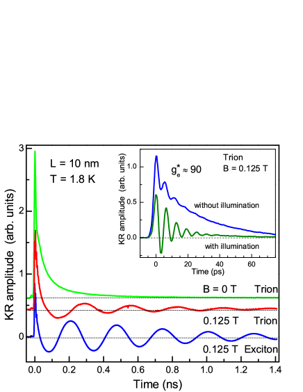
Two Cd1-xMnxTe/Cd0.8-xMnxMg0.20Te quantum well (QW) structures were grown on -oriented GaAs substrates by molecular-beam epitaxy. Each structure consists of three Cd1-xMnxTe QWs with widths of , 6, and 10 nm, separated by 30-nm-thick Cd0.8-xMnxMg0.20Te barriers. The Mn concentration is (sample 041300A) and 0.04 (sample 041700 ). The structures are nominally undoped, but the QWs contain low concentrations of resident holes. This is confirmed experimentally by the pump-probe measurements without and with above-barrier illumination (see inset of Fig. 2), which allows one to tune the concentration of resident carriers in the QWs and even change the type of the majority background carriers Zh09 .
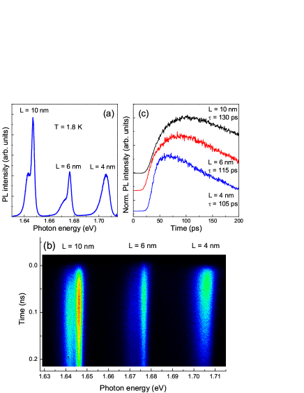
The time-integrated photoluminescence (PL) spectrum of the sample with measured under pulsed excitation (same as streak-camera image described below) with photon energy of 1.718 eV at K is shown in Fig. 1(a). The emission lines are composed of localized excitons and positively charged excitons (T+ trions). They are well resolved in the 6- and 10-nm-thick QWs, where the trion line is a lower energy. In the 4-nm-thick inhomogeneous broadening due to well width fluctuations exceeds the trion binding energy and the exciton and trion lines are not resolved from each other.
The recombination dynamics of excitons and trions were measured by time-resolved PL. The samples were excited by a pulsed Ti:Sapphire laser (pulse duration 1.5 ps, repetition rate 76 MHz, photon energy 1.718 eV) and the emission was detected by a streak-camera attached to a 0.5-m monochromator (time resolution of about 10 ps). The recombination times of the QW exciton and trion in both structures are in the range of 100 ps and do not exceed 130 ps at K (see Figs. 1(b) and 1(c)), which is typical for CdTe and (Cd,Mn)Te based QWs Yakovlev96 ; Yakovlev08 . Despite the presence of the magnetic Mn ions, the dynamic spectral shift of the PL lines to low energies, which would evidence an exciton magnetic polaron formation Yakovlev10 , could not been detected. This is not surprising because, for such low Mn concentrations, small EMP energies ( meV) are expected, so that the EMP formation time can exceed the exciton recombination time. Both factors prevent EMP observation by this experimental technique.
Time-resolved pump-probe Kerr rotation (KR) was used to study the spin dynamics in these structures Zh07 ; Crooker10 . Pulses with a duration of 1.5 ps were taken from a Ti:Sapphire laser with a repetition period ns, which can be extended by a pulse-picker to 26.4, 52.9, 132, or 264 ns in order to analyze long-living processes. The pump pulses were circularly polarized by an elasto-optical modulator operated at 50 kHz frequency and their energy was tuned either to the trion or exciton resonance. The probe pulses were linearly polarized and their Kerr rotation was measured by a balanced photoreceiver. For some measurements, a weak above-barrier illumination with a photon energy of 2.34 eV was used to tune the concentration and type of the resident carriers in the QWs Zh09 ; Deb13 . An external magnetic field of up to 2 T was applied perpendicular to the QW growth axis (Voigt geometry). The sample temperature was varied from to 10 K.
III Experimental results
Pump-probe KR signals measured on the exciton and trion resonances of the 10 nm QW with are shown in Fig. 2. It shows many typical features of DMS QWs, compare, e.g., Refs. Crooker97, and Crooker10, . At zero magnetic field the KR amplitude has a fast and a slow decay component with times of 45 ps and 350 ps, respectively. At T the signal consists of three components. Two of them are fast decaying, they are shown in the inset of Fig. 2. The oscillating component arises from electron spin beats with an effective factor and a dephasing time of about 10 ps. This value corresponds to the slope of the electron giant Zeeman splitting meV/T, which is in agreement with according to the growth parameters. As the hole exchange constant in (Cd,Mn)Te is four times larger than that of the electron, one can evaluate the magnetic field slope of the heavy-hole giant Zeeman splitting as meV/T. The nonoscillating component in the inset is attributed to resident heavy holes with strongly anisotropic factor with an in-plane component close to zero. The relative amplitudes of the electron and hole contributions are changed when the sample is exposed to additional above barrier illumination with a density of 0.3 W/cm2 that enhances the electron contribution. It was shown for CdTe/(Cd,Mg)Te QWs that at low temperatures the electrons photoexcited by above-barrier excitation are predominantly captured by the QWs, while the holes are partly localized in the barriers by alloy fluctuations Zh09 . In the studied structure this decreases the concentration of resident holes. The experimental results in the inset of Fig. 2 let us conclude that the studied samples contain resident holes in the QWs.
The slow precession for delay times of up to 1.4 ns in Fig. 2 is attributed to the Mn2+ spins with factor and dephasing time of 530 ps. The dephasing time decreases to 350 ps at T and then stays about constant up to 2 T, see inset of Fig. 3(a). It is worthwhile mentioning, that the signals measured on the exciton and trion resonances are quite similar to each other. Similar KR signals are also obtained for the 6-nm-thick QW and the 6- and 10-nm-thick QWs with .
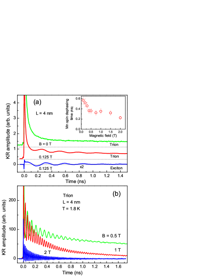
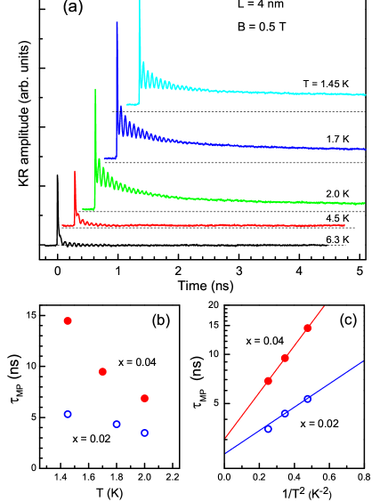
The KR signal measured on the trion in the 4-nm-wide QW with shows a nonoscillatory component with large amplitude and long decay time, see Fig. 3(a). The decay at T exceeds the laser pulse separation ns, as we detect a finite KR amplitude at negative time delays. This component is absent in the signal detected at the exciton resonance. Signals for several magnetic fields are presented in Fig. 3(b). Here, the decay time of the nonoscillating component measured on the trion is ns at T. The decay time and amplitude of this component strongly decrease with further increasing magnetic field up to 2 T.
The magnetic field dependence of the decay time of the nonoscillating component is shown in Fig. 4. We denote this time by , as it is attributed to the directional relaxation of the magnetic moment of the magnetic polaron, i.e., to the magnetic-polaron spin relaxation; it will be shown in the following. One can see that decreases from 60 ns at zero field down to 0.35 ns at T. At zero field was evaluated from the dependence of the KR amplitude at a small negative time delay of 60 ps prior to the pump pulse on the temporal pump-pulse separation , which was varied from 13.2 to 264 ns. The dependence in Fig. 4 can be described by two different ranges: one at low magnetic fields up to 0.1 T, where a fast decrease of occurs, and a second one at higher fields, where the decay becomes much weaker. This evidences that there are two different regimes for the HMP dynamics at low and high magnetic fields, whose features will be discussed in Sec. V.
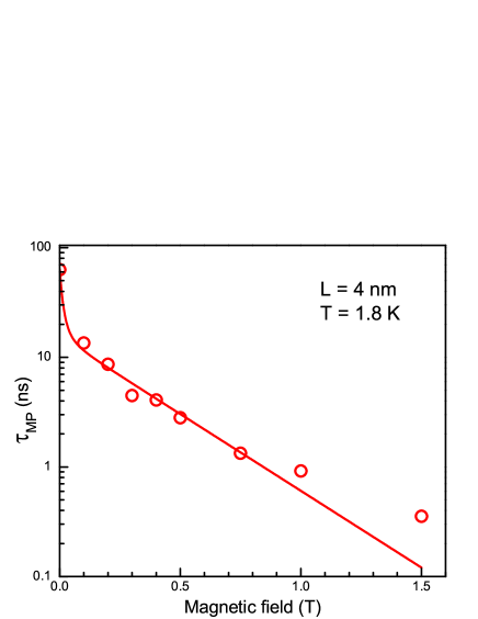
Figure 5(a) presents the KR signals of the 4-nm-thick QW measured at different temperatures. With increasing temperature from 1.45 to 6.3 K the decay time of the nonoscillating component decreases drastically to a value below 100 ps. The temperature dependence of is shown in Fig. 5(b). The time shortening is accompanied with a pronounced amplitude decrease.
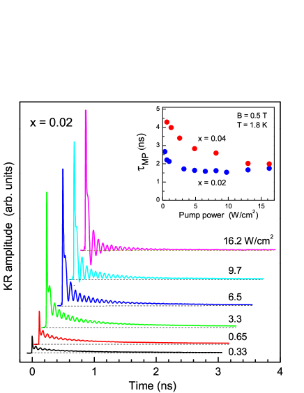
The sample with shows a behavior qualitatively similar to the results of the sample with . In Fig. 6 we show the impact of changes in the pump power on the KR signals from the 4-nm-thick QW with . With increasing power the nonoscillating component disappears, its amplitude decreases and the decay time becomes shorter, see also inset of Fig. 6. In this respect the behavior is similar to that induced by a temperature increase, compare with Fig. 5(a).
The long-lived nonoscillating signal observed in the Voigt geometry for the applied external magnetic fields deserves special attention, as it has not been reported earlier for DMS QWs. It cannot originate from optically oriented electrons or holes, as the carrier spin relaxation times in DMS structures typically do not exceed tens of picoseconds Crooker97 ; Akimoto98 ; Camilleri01 ; Freeman90 . It also unlikely that it is attributed to the dynamics of Mn2+ spins, whose precession is clearly observed with an amplitude that weakly depends on temperature and magnetic field. The unusual properties can be related only to a hole magnetic polaron, for which a strong spin anisotropy, namely a small in-plane factor, is provided by the strongly confined heavy hole, whose spin relaxation becomes locked through the interaction with Mn spins. In the following sections we will analyze the mechanism of the optical orientation of the HMP and the dependence of its spin relaxation time on the temperature and magnetic field strength.
IV Model of optical orientation of hole magnetic polaron
The observed experimental data can be explained by the optical orientation of equilibrium magnetic polarons involving resident holes. In QWs, the heavy-hole and light-hole states with angular momentum projections and , respectively, onto the structure growth axis ( axis) are split by lattice strain and quantum confinement. The lowest heavy-hole state is described as a quasi-particle with strongly anisotropic -factor tensor: Merk95 . A magnetic polaron, which is formed by a heavy hole interacting with Mn spins, therefore also exhibits a strong anisotropy. At zero magnetic field, the polaron formation leads to maximum polaron binding energy (or magnetic polaron energy) , when the magnetic moment of the polaron (the total magnetic moment of the Mn ions inside the hole localization volume) is directed along the axis. Here, is the mean exchange field of the localized hole acting on the Mn spins. For spin relaxation, the HMP should flip its magnetic moment and overcome the energy barrier equal to between two stable states along the axis.
Let us discuss the mechanism of optical generation of spin polarization for an ensemble of equilibrium HMPs localized in a QW. Several aspects should be taken into account: (i) The HMPs involving equilibrium resident holes are in equilibrium, i.e., they have infinite lifetime and their binding energy reaches the value . (ii) The HMPs are formed from the anisotropic heavy-holes with Comm1 . (iii) The circular-polarized photoexcitation is resonant with the lowest possible state that, for the HMP, is the positively charged exciton consisting of two holes in the spin singlet state and an electron Bartsch11 . In this respect the suggested model has some analogy with the model describing the generation of spin coherence in low-density electron or hole gases via resonant excitation of trion states in QWs Zh07 ; Yakovlev08 .
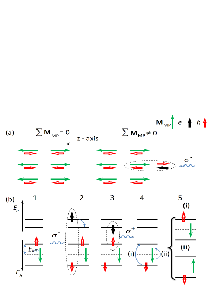
At zero magnetic field the magnetic moments of the HMPs, , are equally distributed between the orientations parallel and antiparallel to the axis so that the total polarization of the HMP ensemble is zero, see Fig. 7(a). The resonant excitation of the trion states by, e.g., circularly polarized light photocreates T+ trions from the resident holes, whose spin is oriented parallel to the axis. As a result, the HMPs formed by these holes become heated (excited) and fully or partly depolarized. This induces a net spin orientation in the ensemble of HMPs. For pump-probe KR detection the signal is contributed by the unperturbed HMPs with parallel to the axis. It is interesting that in this case we are thus able to study the properties of equilibrium HMPs, which are not affected by photoexcitation. This is different from common optical orientation experiments, where the polarized photoluminescence of photoexcited spin-oriented carriers is analyzed.
Let us discuss in detail the depolarization mechanism of photoexcited HMPs. The respective schematic diagrams are shown in Fig. 7(b). Stage 1 corresponds to the equilibrium HMP, here the hole spin is antiparallel to . It is important to note, that the spin splitting of the hole and electron states is not induced by an external magnetic field, which is zero, but is due to carrier exchange interaction with the polaron magnetic moment. The photoexcitation of the trion ground state from this resident hole with circularly polarized light is shown as stage 2. Here, a hole with spin-down is generated (spin-up state is already occupied by the resident hole) and an electron with spin-up. For the electron, this is an energetically unfavorable orientation and it relaxes into the spin-down state. Then, the spin-down electron recombines with the spin-up hole resulting in emission of a polarized photon (stage 3) and leaving the resident spin-down hole in an orientation unfavorable for (stage 4). There are two ways to obtain again the favorable orientation: (i) to flip the hole spin and end up with an orientation identical to the initial one (stage 1), or (ii) to flip , which will change the order of the spin levels for holes and provide a HMP with an orientation opposite to the initial one. As a result, the subensemble of spin-up oriented HMPs becomes partly depolarized, which in turn leads to optical orientation of the whole ensemble of HMPs. Note, that both electron and hole spin relaxation in presence of requires a dissipation of energy, which is typically transferred to phonons or the Mn spin reservoir and, therefore, heats the Mn spin system inside the HMP. This heating may induce a reorientation of .
V Model of spin relaxation of anisotropic hole magnetic polaron
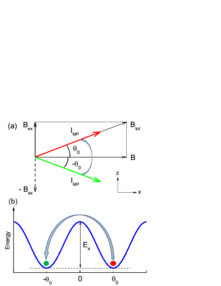
The excited optical orientation of the HMPs relaxes with the polaron spin relaxation time . It is important that due to their anisotropic spin structure the HMPs do not participate in coherent spin precession about an external magnetic field, but rather show up as decaying contribution to the pump-probe Kerr rotation signal. To flip , i.e., to provide polaron spin relaxation, it is necessary to overcome a barrier with an activation energy , as shown schematically in Fig. 8(b). At zero external magnetic field is equal to , but the barrier decreases at a finite magnetic field strength. At low temperatures () the HMP spin relaxation can last very long, in the studied structures up to 60 ns. With growing temperature the spin-flip probability of the polaron magnetic moment increases. The strong temperature dependence of the HMP spin-relaxation time observed in the experiment suggests that it occurs due to an activation process, which can be described by
| (1) |
Here, is a pre-factor of the order of the hole spin-flip time. In this section we will model the magnetic field and temperature dependences of to describe the experimental observations and evaluate the HMP parameters.
To calculate the dependence of the activation energy on the external magnetic field, we make use of the theory of an anisotropic magnetic polaron formed by holes in quantum wells, developed by Merkulov and Kavokin Merk95 . The magnetic polaron (MP) possesses a huge angular momentum mainly due to the total spin of many Mn ions within the localization volume of the hole. The spin Hamiltonian of the exchange-coupled Mn and hole-spins in a magnetic field ,
| (2) |
comprises four parts: the exchange interaction, the Zeeman interaction of the Mn ions, the Zeeman interaction of the hole (the latter is usually neglected because it is much smaller than the exchange interaction with the Mn ions), and the spin-orbit interaction responsible for splitting the heavy- and light-hole subbands in QWs. Here, is the p-d exchange constant, is the hole spin, is the spin of the i-th Mn ion located at the the position vector , is the hole envelope function, is the factor of the Mn2+ ion, and is the Bohr magneton. Numerous previous studies have shown that the experimental manifestations of the MP are well described by the ”box” model, replacing the operator with the total spin operator of the Mn ions within the magnetic polaron volume that is defined by
| (3) |
Within the ”box” approximation, the Hamiltonian (2) takes a simplified form
| (4) |
If the energy splitting between the heavy holes and light holes is much larger than the exchange energy of the hole (which is true in narrow quantum wells), one can use a truncated Hamiltonian restricted to the ground-state heavy-hole spin doublet. Merkulov and Kavokin Merk95 suggested writing it in the form
| (5) |
Here, is the pseudospin operator of the hole with the components given by the Pauli matrices defined in the heavy-hole subspace (note that the exchange constant in Ref. Merk95, equals to ), is the tensor of the effective factor of the heavy hole (usually ), and .
While at the initial stages of MP formation its energy may be determined by fluctuations of the Mn total spin , once the MP is formed, the main contribution to the energy comes from the interaction of the hole spin with the mean vector (collective regime). In this regime, the hole occupies the lowest spin level in the effective field generated by the polarized Mn spins, and the polaron energy can be written as
| (6) |
Here, the are the components of the mean total spin of the Mn ions inside the polaron volume, and the are the components of the mean hole pseudospin, which is a Bloch vector defining a linear combination of states within the heavy-hole doublet. We choose the z axis to be normal to the QW plane, i.e., parallel to the structure growth axis. We would like to stress here that Eq. (6) describes not only the ground state of the polaron, but also states with arbitrary direction of . The activation energy is equal to the energy difference between the polaron ground state and the highest point of the transition path (see Fig. 8(b)). Let us first calculate the energy for the polaron ground state as a function of the applied magnetic field.
We consider the Voigt geometry, when the magnetic field is in the QW plane and has only a component along the axis: . Since for II-VI diluted magnetic semiconductors the p-d exchange constant is negative (), in the polaron ground state the hole pseudospin is anti-parallel to and should be minimal. This consideration leads to the following expressions for the components of :
| (7) | |||||
As a function of the angle between and the in-plane magnetic field , remains close to , while . In this range of angles the polaron energy is given by a simple expression:
| (8) |
It reaches the minimum value at , which corresponds to the ground state of the polaron. The energy of this state is
| (9) | |||||
where
| (10) |
is the exchange field generated by the hole (see Eq. (7.12) of Ref. Yakovlev10, , note that ). For simplicity, we will continue the considerations by suggesting a linear dependence of the Mn polarization on . This approach is valid for the conditions of our experiment, where T and the expected T. The magnitude of in the polaron ground state, , is determined by the total field that is applied to the Mn ions within the polaron, which is the vector sum of the external field and the exchange field:
| (11) |
where is the magnetic susceptibility of the Mn ions. Note that the magnitude of the HMP magnetic moment is .
The two ground states of the HMP in an external magnetic field are shown schematically in Fig. 8(a). The blue arrow marks the transition between these states, which provides the spin relaxation of the HMP with the characteristic time .
Relaxation of the HMP magnetic moment is provided by changing the orientation of between its stable states at , see Fig. 8(b). The highest point of the most probable activation path of is at (where the polaron energy has a saddle point as function of the direction of ). At this point,
| (13) | |||||
The activation energy is given by
| (14) |
Note that at zero external magnetic field the HMP is aligned along the z axis (), and the polaron energy according to Eq. (9) is given by
| (15) |
Here, is the magnetic polaron binding energy, which has by definition a positive value Kavokin99b ; Yakovlev10 . In the linear approximation the expression for the HMP energy can be obtained using the definition of the exchange field (Eq. (10)):
| (16) |
where is the hole Zeeman splitting in Faraday geometry.
In this case we obtain
| (17) |
The magnetic field dependence of the activation energy, given by Eq. (17), can be split in two ranges. In weak external fields, the ground-state polaron energy does not change considerably, because the external field is applied perpendicular to the hole exchange field. Therefore, the lowering of the activation energy is determined by the change of the barrier height, equal to the Zeeman shift of the lowest hole spin level:
| (18) |
When the external field becomes comparable in strength with the hole exchange field, the total energy of the polaron in its ground state starts to decrease with increasing external field, thus compensating the decrease of the barrier height. As a result, the lowering of the activation energy is considerably weakened:
| (19) |
The crossover between the two regimes occurs at . As one can see from Eq. (19), in the case of the field dependence of the activation energy saturates at . Its slope for gives the ratio of the principal values of the hole -factor tensor . These two regimes are clearly seen in Fig. 9(a), where the activation energy normalized to the magnetic polaron energy at zero magnetic field is plotted as a function of the magnetic field, expressed in units of the exchange field .
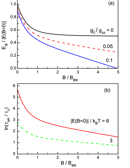
The magnetic field dependence of the polaron relaxation time calculated after Eqs. (1) and (17) is shown in Fig. 9(b). In order to have it in a universal form and highlight the two regimes, the results are presented by using normalized values, namely is plotted versus . Here, the parameter of the shown dependences is the ratio of the HMP energy at zero field to . A larger corresponds to a higher potential barrier between the two stable HMP states, and correspondingly to a longer spin relaxation time.
It is insightful to relate the polaron parameters determined by the fit of the magnetic field dependence of the MP spin relaxation time to the MP binding energy usually measured in photoluminescence spectra under selective excitation. As found in Ref. Merk95, , the MP is destroyed by an in-plane magnetic field when its strength becomes larger than the critical field given by Eq.(15) of this paper. In our notation,
| (20) |
One can see that the magnetic fields applied in our experiment are well below , and, therefore, the MP binding energy should approximately be equal to its value at zero magnetic field
| (21) |
VI Discussion
Let us apply the developed model to the experimental data on the HMP spin relaxation. A strong dependence of on the magnetic field has been found experimentally, see Fig. 4. The line shows the best fit to the data using Eqs. (1) and (17), for which the value meV/T was taken from the measured electron spin beats in the inset of Fig. 2. The two fitting parameters and are in fact independent, as they are linked to the characteristic field, where the slope changes, and to the slope in high magnetic fields, respectively. is in good agreement with the expectation of a strongly anisotropic heavy-hole spin state in narrow QWs. T corresponds to a binding energy of the HMP of meV for the QW with . These values are reasonable for QWs with low Mn concentrations Merk ; Kusrayev08 .
The temperature dependence of shown in Fig. 5(c) is in agreement with the HMP energy evaluated from its magnetic field dependence. Here, the parameters of the linear interpolations shown by the lines are for and for . This means that at T, and 2.5 ns in the samples with and 0.02, respectively. This time is a pre-factor, which is of the order of the hole spin-flip time.
The approach developed in Ref. Kavokin99b, allows us to evaluate the volume of the HMP. For that, we use Eq. (10) with the known parameters for (Cd,Mn)Te: meV and nm3 Furdyna88 . For the 4-nm-thick QW with , where T, the estimated HMP volume is nm3. Accordingly, the localization radius of the resident hole is about 19 nm, which is reasonable for the QW width fluctuations.
The mechanism of optical orientation of equilibrium magnetic polarons in DMS QWs suggested in this paper has not been reported so far. Here, it has been demonstrated experimentally for hole MPs, but it is equally valid for electron MPs, as well as for donor-bound and acceptor-bound MPs. The mechanism has some similarity with the mechanism for spin coherence generation in electron- and hole-gases of low density in nonmagnetic QWs and in singly-charged quantum dots under resonant trion excitation. It has been validated for GaAs-, (In,Ga)As-, CdTe- and ZnSe-based QWs and (In,Ga)As-based quantum dots, for which charged exciton (trion) states are of key importance for the optical properties Yakovlev08 ; Zh07 ; Fokina10 ; Zh14 .
The suggested mechanism for equilibrium magnetic polarons is fundamentally different from the one for optical orientation of exciton magnetic polarons (EMP) that was reported for bulk (Cd,Mn)Se and for (Cd,Mn)Te- and (Cd,Mn)Te-based QWs Warnock1 ; Warnock2 ; Merkulov95 . There are several aspects to distinguish:
(i) For exciton MPs optical excitation was performed in the tail of localized exciton states and the degree of induced optical orientation is controlled by the magnetic fluctuations of Mn spins, , in the exciton volume, prior the evolution of the collective polaron. In the suggested mechanism, does not play a key role for the generation efficiency.
(ii) The EMP lifetime is limited by exciton recombination (typically in the range of ps in direct band gap semiconductors). As a result, EMP cannot always reach their equilibrium polaron energy. Also, EMPs cannot be considered as suitable candidates for a long-term spin memory. Contrary to that, the equilibrium MPs formed from resident holes (or electrons) do not suffer from recombination; as they are in equilibrium, their energy is not influenced by dynamical factors.
(iii) In the case of the orientation of the equilibrium MPs via resonant excitation of the underlying trion state we do not induce a perturbation of the equilibrium MPs whose dynamics are in focus of our measurements. Instead, we rearrange the orientation of the other polarons in the ensemble. Due to that we have the possibility to study the properties of the equilibrium MP state, which remains unperturbed by the optical excitation. This is as well different from the EMP optical orientation, where the oriented MPs are formed from the photogenerated excitons.
VII Conclusions
We report on the observation of equilibrium hole magnetic polarons in (Cd,Mn)Te/(Cd,Mn,Mg)Te QWs. Their optical orientation is provided by resonant excitation of the trion states in these structures. The long spin relaxation times of the magnetic polarons up to 60 ns are provided by the anisotropic spin state of the heavy holes in the QWs. These times may be further extended in structures with higher Mn concentrations and enhanced carrier localization, which result in larger polaron energies. The suggested mechanism of optical orientation allows for the study of the polaron spin dynamics by time-resolved pump-probe Kerr rotation. The mechanism is valid for both the collective and fluctuation regimes of hole or electron MPs and also for bound magnetic polarons, where the resident carrier is bound either to a donor (electron) or an acceptor (hole).
Acknowledgements We acknowledge the financial support by the Russian Science Foundation (Grant No. 14-42-00015) and the Deutsche Forschungsgemeinschaft in the frame of ICRC TRR 160. The research in Poland was partially supported by the National Science Centre (Poland) through Grants No. DEC-2012/06/A/ST3/00247 and No. DEC-2014/14/M/ST3/00484 and by the Foundation for Polish Science through the Master program (G.K.).
References
- (1) Semiconductor Spintronics and Quantum Computation, Eds. D. D. Awschalom, D. Loss, and N. Samarth (Springer-Verlag, Heidelberg, 2002).
- (2) Optical Generation and Control of Quantum Coherence in Semiconductor Nanostructures, Eds. G. Slavcheva and P. Roussignol (Springer-Verlag, Berlin, 2010).
- (3) Optical Orientation, Eds. F. Meier and B. P. Zakharchenya (North-Holland, New York, 1984).
- (4) S. A. Crooker, J. J. Baumberg, F. Flack, N. Samarth, and D. D. Awschalom, Terahertz spin precession and coherent transfer of angular momenta in magnetic quantum wells, Phys. Rev. Lett. 77, 2814 (1996).
- (5) S. A. Crooker, D. D. Awschalom, J. J. Baumberg, F. Flack, and N. Samarth, Optical spin resonance and transverse spin relaxation in magnetic semiconductor quantum wells, Phys. Rev. B 56, 7574 (1997).
- (6) R. Akimoto, K. Ando, F. Sasaki, S. Kobayashi, and T. Tani, Larmor precession of Mn2+ moments initiated by the exchange field of photoinjected carriers in CdTe/(Cd,Mn)Te quantum wells, Phys. Rev. B 57, 7208 (1998).
- (7) H. Krenn, K. Kalteneger, T. Dietl, J. Spalek, and G. Bauer, Photoinduced magnetization in dilute magnetic (semimagnetic) semiconductors, Phys. Rev. B 39, 10918 (1989).
- (8) S. A. Crooker, Coherent spin dynamics of carriers and magnetic ions in diluted magnetic semiconductors, Chapter 9 in Introduction to the Physics of Diluted Magnetic Semiconductors, Eds. J. Kossut and J. A. Gaj (Springer-Verlag, Berlin, 2010), pp. 305-334, ISBN 978-3-642-15855-1.
- (9) I. A. Akimov, R. I. Dzhioev, V. L. Korenev, Yu. G. Kusrayev, V. F. Sapega, D. R. Yakovlev, and M. Bayer, Optical orientation of Mn2+ ions in GaAs in weak longitudinal magnetic fields, Phys. Rev. Lett. 106, 147402 (2011).
- (10) D. R. Yakovlev and I. A. Merkulov, Spin and energy transfer between carriers, magnetic ions, and lattice, Chapter 8 in Introduction to the Physics of Diluted Magnetic Semiconductors, Eds. J. Kossut and J. A. Gaj (Springer-Verlag, Berlin, 2010), pp. 263-303, ISBN 978-3-642-15855-1.
- (11) J. Warnock, R. N. Kershaw, D. Ridgely, K. Dwight, A. Wold, and R. R. Galazka, Localized excitons and magnetic polaron formation in (Cd, Mn)Se and (Cd, Mn)Te, J. Luminescence 34, 25 (1985).
- (12) J. Warnock, R. N. Kershaw, D. Ridgely, K. Dwight, A. Wold, and R. R. Galazka, Optical orientation of excitons in (Cd,Mn)Se and (Cd,Mn)Te, Solid State Communications 54, 215 (1985).
- (13) I. A. Merkulov, D. R. Yakovlev, K. V. Kavokin, G. Mackh, W. Ossau, A. Waag, and G. Landwehr, Hierarchy of relaxation times in the formation of an excitonic magnetic polaron in (CdMn)Te, JETP Lett. 62, 335 (1995) [Pis’ma Zh. Eksp. Teor. Fiz. 62, 313 (1995)].
- (14) B. P. Zakharchenya, and Yu. G. Kusrayev, Optical manifestation of spin-glass properties of semimagnetic semiconductors, Sov. Phys. JETP Lett. 50, 225 (1989). [Pis’ma Zh. Eksp. Teor. Fiz. 50, 199 (1989)].
- (15) P. A. Wolff, in Diluted Magnetic Semiconductors, Vol. 25 of series ”Semiconductors and Semimetals” Eds. J. K. Furdyna and J. Kossut, (Academic Press, London, 1988) Chapter 10, pp. 413-454, ISBN 0-12-752125-9.
- (16) E. A. Zhukov, D. R. Yakovlev, M. Gerbracht, G. V. Mikhailov, G. Karczewski, T. Wojtowicz, J. Kossut, and M. Bayer, Spin coherence of holes and electrons in undoped CdTe/(Cd,Mg)Te quantum wells, Phys. Rev. B 79, 155318 (2009).
- (17) D. R. Yakovlev, and K. V. Kavokin, Exciton magnetic polarons in semimagnetic quantum wells and superlatices, Comments Cond. Matt. Phys. 18, 51 (1996).
- (18) D. R. Yakovlev and M. Bayer, Coherent spin dynamics of carriers, Chapter 6 in Spin Physics in Semiconductors, pp. 135-177, ed. M. Dyakonov (Springer, Berlin 2008) ISBN: 978-3-540-78819-5.
- (19) D. R. Yakovlev and W. Ossau, Magnetic polarons, Chapter 7 in Introduction to the Physics of Diluted Magnetic Semiconductors, Eds. J. Kossut and J. A. Gaj (Springer-Verlag, Berlin, 2010), pp. 221-262, ISBN 978-3-642-15855-1.
- (20) E. A. Zhukov, D. R. Yakovlev, M. Bayer, M. M. Glazov, E. L. Ivchenko, G. Karczewski, T. Wojtowicz, and J. Kossut, Spin coherence of a two-dimensional electron gas induced by resonant excitation of trions and excitons in CdTe/(Cd,Mg)Te quantum wells, Phys. Rev. B 76, 205310 (2007).
- (21) J. Debus, D. Dunker, V. F. Sapega, D. R. Yakovlev, G. Karczewski, T. Wojtowicz, J. Kossut, and M. Bayer, Spin-flip Raman scattering of the neutral and charged excitons confined in a CdTe/(Cd,Mg)Te quantum well, Phys. Rev. B 87, 205316 (2013).
- (22) C. Camilleri, F. Teppe, D. Scalbert, Y. G. Semenov, M. Nawrocki, M. Dyakonov, J. Cibert, S. Tatarenko, and T. Wojtowicz, Electron and hole spin relaxation in modulation-doped CdMnTe quantum wells, Phys. Rev. B 64, 085331 (2001).
- (23) M. R. Freeman, D. D. Awschalom, J. M. Hong, and L. L. Chang, Femtosecond spin-polarization spectroscopy in diluted-magnetic-semiconductor quantum wells, Phys. Rev. Lett. 64, 2430 (1990).
- (24) I. A. Merkulov and K. V. Kavokin, Two-dimensional magnetic polarons: Anisotropic spin structure of the ground state and magneto-optical properties, Phys. Rev. B 52, 1751 (1995).
- (25) We do not consider here effects related to the mixing of heavy- and light-hole states with increasing magnetic field and the appearance of nonzero in-plane components of the heavy-hole spin. While their presence would not change the basics of the suggested approach and can be accounted by its elaboration.
- (26) G. Bartsch, M. Gerbracht, D. R. Yakovlev, J. H. Blokland, P. C. M. Christianen, E. A. Zhukov, A. B. Dzyubenko, G. Karczewski, T. Wojtowicz, J. Kossut, J. C. Maan, and M. Bayer, Positively versus negatively charged excitons: A high magnetic field study of CdTe/Cd1-xMgxTe quantum wells, Phys. Rev. B 83, 235317 (2011).
- (27) I. A. Merkulov, G. R. Pozina, D. Coquillat, N. Paganotto, J. Siviniant, J. P. Lascaray, and J. Cibert, Parameters of the magnetic polaron state in diluted magnetic semiconductors Cd-Mn-Te with low manganese concentration, Phys. Rev. B 54, 5727 (1996).
- (28) Yu. G. Kusrayev, K. V. Kavokin, G. V. Astakhov, W. Ossau, and L. W. Molenkamp, Bound magnetic polarons in the very dilute regime, Phys. Rev. B 77, 085205 (2008).
- (29) K. V. Kavokin, I. A. Merkulov, D. R. Yakovlev, W. Ossau, and G. Landwehr, Exciton localization in semimagnetic semiconductors probed by magnetic polarons, Phys. Rev. B 60, 16499 (1999).
- (30) L. V. Fokina, I. A. Yugova, D. R. Yakovlev, M. M. Glazov, I. A. Akimov, A. Greilich, D. Reuter, A. D. Wieck, and M. Bayer, Spin dynamics of electrons and holes in InGaAs/GaAs quantum wells at millikelvin temperatures, Phys. Rev. B 81, 195304 (2010).
- (31) E. A. Zhukov, D. R. Yakovlev, A. Schwan, O. A. Yugov, A. Waag, L. W. Molenkamp, and M. Bayer, Spin coherence of electrons and holes in ZnSe-based quantum wells studied by pump-probe Kerr rotation, Physica Status Solidi (b) 251, 1872 (2014).
- (32) J. K. Furdyna, Diluted magnetic semiconductors, J. Appl. Phys. 64, R29 (1988).