SDNsec: Forwarding Accountability
for the SDN Data Plane
Abstract
SDN promises to make networks more flexible, programmable, and easier to manage. Inherent security problems in SDN today, however, pose a threat to the promised benefits. First, the network operator lacks tools to proactively ensure that policies will be followed or to reactively inspect the behavior of the network. Second, the distributed nature of state updates at the data plane leads to inconsistent network behavior during reconfigurations. Third, the large flow space makes the data plane susceptible to state exhaustion attacks.
This paper presents SDNsec, an SDN security extension that provides forwarding accountability for the SDN data plane. Forwarding rules are encoded in the packet, ensuring consistent network behavior during reconfigurations and limiting state exhaustion attacks due to table lookups. Symmetric-key cryptography is used to protect the integrity of the forwarding rules and enforce them at each switch. A complementary path validation mechanism allows the controller to reactively examine the actual path taken by the packets. Furthermore, we present mechanisms for secure link-failure recovery and multicast/broadcast forwarding.
1 Introduction
Software Defined Networking (SDN) and its current realization – OpenFlow [1] – promise to revolutionize networking by centralizing network administration and eliminating vendor lock-in. Rapid service deployment, simplified network management, and reduced operational costs are some of the promised benefits. Furthermore, SDN serves as a building block to mitigate network security issues [2, 3, 4]. Ironically, though, security of SDN itself is a neglected issue.
SDN is rife with vulnerabilities at the data plane. Compromised switches [5, 6, 7] can redirect traffic over unauthorized paths to perform eavesdropping, man-in-the-middle attacks, or to bypass security middleboxes [8]. Furthermore, they can disrupt availability by launching state exhaustion attacks against other switches [8, 9, 10] or by simply dropping packets. In addition, next generation botnets, consisting of compromised hosts and switches, could unleash an unprecedented firepower against their victims. There are latent vulnerabilities in SDN today that make these attacks feasible.
The first problem lies in the adversary model for the data plane: all network devices are trusted to correctly follow the specified network policies. Thus, the data plane lacks accountability mechanisms to verify that forwarding rules are correctly applied. Specifically, it does not provide guarantees that the policies will be followed (enforcement) nor proof that policies have not been violated (validation). Once one or more switches get compromised, forwarding policies can be violated without getting caught by other switches or the controller.
Another problem is the lack of consistency guarantees when the forwarding plane is reconfigured [11]. During reconfigurations, packets can follow paths that do not comply with policy, leading to link flooding or isolation violations in multitenant environments. This is an inherent problem in distributed systems, because the new policy is correctly applied only after all affected switches have been updated. However, an attacker can exploit the problem by forcing reconfigurations through a compromised switch.
Our goal is to build an SDN security extension which ensures that the operator’s policies are correctly applied at the data plane through forwarding accountability mechanisms. That is, the extension should ensure consistent policy updates, enforce network paths, and provide a means for operators to reactively inspect how traffic has been forwarded.
There are only a few proposals dealing with SDN data-plane security. A recent security analysis of OpenFlow [9] proposes simple patch solutions (rate limiting, event filtering, and packet dropping) to counter resource exhaustion attacks. SANE [12], a pre-SDN era proposal, proposes a security architecture to protect enterprise networks from malicious switches. However, it lacks a validation mechanism to ensure that a path was indeed followed; failure recovery is pushed to the end hosts. Another class of proposals checks for policy violations by examining certain network invariants; checking can be performed in real time during network reconfigurations [3, 13, 14] or by explicitly requesting the state of the data plane [15].
Contributions
This paper proposes an SDN security extension, SDNsec, to achieve forwarding accountability for the SDN data plane. Consistent updates, path enforcement, and path validation are achieved through additional information carried in the packets. Cryptographic markings computed by the controller and verified by the switches construct a path enforcement mechanism; and cryptographic markings computed by the switches and verified by the controller construct a path validation mechanism. Furthermore, we describe mechanisms for secure failure recovery. Finally, we implement the SDNsec data plane on software switches and show that state exhaustion attacks are confined to the edge of the network.
2 Problem Description
We consider a typical SDN network with a forwarding plane that implements the operator’s network policies through a logically centralized controller. Network policies of the operator dictate which flows are authorized to access the network and which paths are authorized to forward traffic for the corresponding flows.
Our goal is to design an extension that makes a best-effort attempt to enforce network policies at the forwarding plane, and to detect and inform the controller in case of policy violations.
2.1 Adversary Model
The goal of the attacker is to subvert the network policies of the operator (e.g., by forwarding traffic over unauthorized paths) or to disrupt the communication between end hosts. To this end, we consider the following attacks:
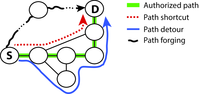
Path deviation
A switch causes packets of a flow to be forwarded over a path that has not been authorized for the specific flow. This attack can take the following forms (Figure 1):
-
•
Path detour
A switch redirects a packet to deviate from the original path, but later the packet returns to the correct next-hop downstream switch.
-
•
Path forging
A switch redirects a packet to deviate from the original path, but the packet does not return to a downstream switch of the original path.
-
•
Path shortcut
A switch redirects a packet and skips other switches on the path; the packet is forwarded only by a subset of the intended switches.
Packet replay
A switch replays packet(s) to flood a host or another switch.
Denial-of-Service
We consider state exhaustion attacks against switches, which disrupt communication of end hosts.
We consider an adversary that can compromise infrastructure components and hosts, and can exploit protocol vulnerabilities. Furthermore, compromised components are allowed to collude.
We do not consider payload modification attempts by switches, as hosts do not trust the network and use end-to-end integrity checks to detect any unauthorized changes. In addition, controller security is out of the scope of this paper, since our goal is to enforce the controller policies at the forwarding plane.
2.2 Assumptions
We make the following assumptions:
-
•
Cryptographic primitives are secure, i.e., hash functions cannot be inverted, signatures cannot be forged, and encryptions cannot be broken.
-
•
The communication channel between the controller and benign switches is secure (e.g., TLS can be used, as in OpenFlow [1]).
-
•
End hosts are authenticated to the controller and cannot spoof their identity (e.g., port-based Network Access Control can be used [16]).
3 Overview
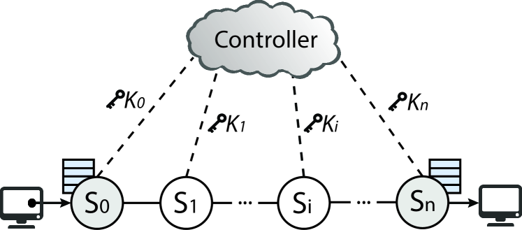
In SDNsec, the controller computes network paths and the corresponding forwarding information. The switches at the edge of the network receive this forwarding information over a secure channel and embed it into packets that enter the network. Switches at the core of the network forward packets according to the forwarding information carried in the packets; and the last switch on the path removes the embedded information before forwarding the packet to the destination. Figure 2 shows the network model for SDNsec. We stress that end hosts do not perform any additional functionality (e.g., communicate with the controller), i.e., the network stack of the hosts is unmodified.
We describe and justify our main design decisions and present an overview of the control and data plane.
3.1 Central Ideas
We identify three main problems that undermine network policies in today’s SDN networks and describe our corresponding design decisions.
Consistent Updates
In SDN, the distributed nature of updating the forwarding plane can cause inconsistencies among switches. Specifically, a new policy is correctly applied only after all affected switches have been reconfigured; however, during state changes the forwarding behavior may be ill-defined. Although solutions have been proposed to counter this problem [17, 18], they require coordination between the controller and all the involved switches in order to perform the updates.
In SDNsec, packets encode the forwarding information for the intended path. This approach guarantees that once a packet enters the network, the path to be followed is fixed and cannot change under normal operation (i.e., without link failures). Hence, a packet cannot encounter a mixture of old and new forwarding policies, leading to inconsistent network behavior. Forwarding tables exist only at the entry and exit points of the network, simplifying network reconfiguration: only the edge of the network must be updated and coordination among all forwarding devices is not needed.
The packet overhead we have to pay for this approach provides additional benefits: guaranteed loop freedom, since we eliminate asynchronous updates; and minimum state requirements for switches, since forwarding tables are not needed in most of the switches (see Section 3.3). The lack of forwarding tables confines the threat of state exhaustion attacks.
Path Enforcement
In SDN, the controller cannot obtain guarantees that the forwarding policies will be followed, since the forwarding plane lacks enforcement mechanisms. Ideally, when a switch forwards packets out of the wrong port, the next-hop switch detects the violation and drops the packet.
We incorporate a security mechanism that protects the integrity of the forwarding information in order to detect deviations from the intended path and drop the traffic. However, this mechanism by itself is insufficient to protect from replaying forwarding information that has been authorized for other flows.
Path Validation
In SDN, the controller has no knowledge of the actual path that a packet has taken due to the lack of path validation mechanisms.
We design a reactive security mechanism that checks if the intended path was followed. The combination of path enforcement and path validation provides protection against strong colluding adversaries.
3.2 Controller
The controller consists of two main components: a path computation component (PCC) and a path validation component (PVC). Furthermore, the controller generates and shares a secret key with every switch at the data plane; the shared key is communicated over the secure communication channel between them.
3.2.1 Path Computation Component
The PCC computes the forwarding information for paths that are authorized for communication. Specifically, for each flow that is generated, a path is computed. We do not impose restrictions on the flow specification; for interoperability with existing deployments, we adopt the 13-tuple flow specification of OpenFlow [19].
The computed forwarding information for a flow is embedded in every packet of the flow. For each switch on the path, the PCC calculates the egress interface that the packet should be forwarded on111We assume a unique numbering assignment for the ports of a switch.. Hence, the ordered list of interfaces specifies the end-to-end path that the packets should follow. Furthermore, each flow and its corresponding path is associated with an expiration time () and a flow identifier (). The expiration time denotes the time at which the flow becomes invalid, and the flow identifier is used to optimize flow monitoring in the network (Section 4.4).
Furthermore, the forwarding information contains cryptographic primitives that realize path enforcement. Each forwarding entry () for switch contains a Message Authentication Code (MAC) that is computed over the egress interface of the switch (), the flow information (ExpTime and FlowID), and the forwarding entry of the previous switch (); the MAC is computed with the shared key () between the controller and the corresponding switch on the path. Equation 1 and Figure 2 illustrate how the forwarding information is computed recursively for switch (for ).
| (1) | ||||
Furthermore, a forwarding entry for switch is inserted into the packet to be used by for correct verification of its own forwarding information; is not used by the first-hop switch and is computed as follows: .
3.2.2 Path Validation Component
The PVC is a reactive security mechanism that provides feedback/information about the path that a packet has taken. The controller can then detect attacks that have bypassed path enforcement and reconfigure the network accordingly. Path validation is achieved through two mechanisms: a path validation field in the packet and flow monitoring.
Each switch embeds a proof in every packet that it has indeed forwarded the packet. Hence, the collective proof from all on-path switches forms a trace for the path that the packet has taken. The controller can instruct any switch to report packet headers and thus inspect the path that was taken.
The path validation field of a switch () contains a MAC that is computed over the PVF of the previous switch ()), flow related information (), and a sequence number (). The SeqNo is used to construct mutable information per packet, ensuring different PVF values for different packets; this detects replay attacks of the PVFs. The MAC is computed with the shared key between the switch and the controller222For ease of exposition, the MAC of the PVF is computed with the same key as the MAC of the FE. In a real deployment, these two keys would be different.. Equation 2 shows how the PVF is computed:
| (2) | ||||
Given the and in the packet header, the controller can detect path deviations. The controller knows the path for the given flow, and thus the keys of the switches on the path. Thus, the controller can recompute the correct value for the PVF and compare it with the reported one. However, this mechanism cannot detect dishonest switches that do not report all packet headers when requested.
Monitoring and flow statistics are additional mechanisms to detect false reporting.333Monitoring is an essential tool for other crucial tasks as well (e.g., traffic engineering). The controller can instruct arbitrary switches to monitor specific flows and obtain their packet counters. Inconsistent packet reports indicate potential misbehavior and further investigation is required. For instance, if all switches after a certain point on the path report a lower packet count, then packets were possibly dropped. However, if only a switch in the middle of the path reports fewer packets, it indicates a dishonest report. The controller combines flow monitoring with the PVF in the packet headers to detect policy violations.
3.3 Data Plane
The data plane of SDNsec consists of edge and core switches (Figure 2). Edge switches (shaded circles) operate at the edge of the network and serve as the entry and exit points to the network. Core switches operate in the middle of the network and forward packets based on the forwarding information in the packets.
3.3.1 Edge Switches
Edge switches are directly connected to network hosts and perform different operations when acting as an entry point (ingress switch) and when acting as an exit point (egress switch). Edge switches, as opposed to core switches, have flow tables in order to forward packets.
Ingress Switch
An ingress switch receives packets from source hosts and uses a forwarding table to look up the list of forwarding entries for a specific flow. In case of a lookup failure, the switch consults the controller and obtains the corresponding forwarding information.
Next, the switch creates a packet header and inscribes the forwarding information in it. Furthermore, for every packet of a flow, the switch inscribes a sequence number to enable replay detection of the PVF. Finally, the switch inscribes , and forwards the packet to the next switch.
Egress Switch
An egress switch receives packets from a core switch and forwards them to the destination. To forward a packet, the egress switch uses a forwarding table in the same way as the ingress switch.
Having a forwarding table at the egress switch is a design decision that limits the size of forwarding tables at ingress switches. It allows rule aggregation at ingress switches at the granularity of an egress switch. Without a forwarding table at the egress switch, a separate flow rule for every egress port of an egress switch would be needed. The egress switch has the egress interface encoded in its FE, but it does not consider it when forwarding the packet; the FE is still used to verify the correct operation of the previous hop.
Upon packet reception, the switch removes the additional packet header and forwards the packet to the destination. If requested, it reports the packet header, together with its PVF to the controller.
3.3.2 Core Switches
Core switches operate in the middle of the network and perform minimal operations per packet. They verify the integrity of their corresponding forwarding entry and forward the packet out of the specified interface. In case of a verification failure, they drop the packet and notify the controller.
4 Details
First, we present the SDNsec packet header. Then, we describe link-failure recovery, multicast/broadcast forwarding, and monitoring.
4.1 SDNsec Packet Header
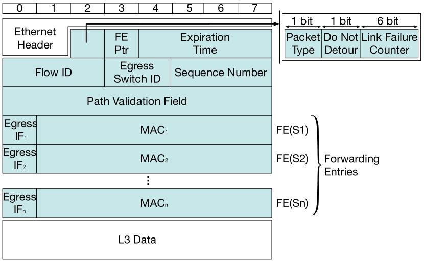
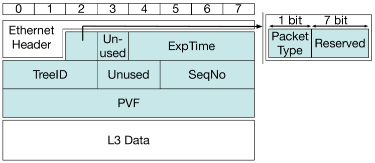
The packet header (Figure 3) encodes the forwarding information (Equation 1), the PVF (Equation 2), and additional information that enables the switches to parse the header (e.g., a pointer to the correct forwarding entry). We present the packet-header fields categorized by their use.
4.1.1 Fields for Forwarding and Path Enforcement
-
•
Packet Type(PktType): PktType indicates whether the packet is a multicast/broadcast or a unicast packet. A single bit is used as a boolean flag to indicate the packet type.
-
•
FE Ptr: A pointer that points to the FE that a switch on the path must examine. During packet processing, each switch increments the pointer so that the next-hop switch examines the correct FE. One byte is allocated for the FE Ptr, which means that SDNsec can support up to 255 switches for a single path. This upper bound does not raise practical considerations even for large topologies, since the network diameter is typically much shorter.
-
•
Expiration Time (ExpTime): ExpTime indicates the time after which the flow becomes invalid. Switches discard packets with expired forwarding information. ExpTime is expressed at the granularity of one second, and the four bytes can express up to 136 years.
-
•
Forwarding Entry (FE): A FE for switch consists of the egress interface of switch () and the MAC () that protects the integrity of the partial path that leads up to the switch . One byte is used for allowing each switch to have up to 255 interfaces; and 7 bytes are used for . In Section 5.1, we justify why a 7-byte MAC is sufficient to ensure path integrity.
4.1.2 Fields for Path Validation
-
•
Path Validation Field (PVF): Each switch that forwards the packet inserts a cryptographic marking on the PVF according to Equation 2, and the controller uses the PVF for path validation. SDNsec reserves 8 bytes for PVF, and in Section 5.1, we justify that 8 bytes provide sufficient protection against attacks.
-
•
Sequence Number (SeqNo): The ingress switch inserts a monotonically increasing packet counter in every packet it forwards. Specifically, a separate counter is kept for every flow entry at the ingress switch. The SeqNo is used to randomize the PVF and to detect replay attacks against the Path Validation mechanism, in which a malicious switch replays valid PVFs to validate a rogue path. The 24-bit sequence number can identify more than 16 million unique packets for a given flow. For the average packet size of 850 bytes in data centers [20], the 24 bits suffice for a flow size of 13 GB; Benson et al. report that the maximum flow size is less than 100 MB for the 10 data centers studied [21]. Hence, it is highly unlikely that the sequence number wraps around. Even if the sequence number wraps around, under normal operation the same values would appear a few times, whereas in an attack scenario typically a high repetition rate of certain values would be observed.
-
•
Flow ID (FlowID): FlowID is an integer that uniquely identifies a flow. FlowIDs are used to index flow information, enabling SDNsec entities (controller and switches) to efficiently search for flow information; the 3 bytes can index over 16 million flows. The active flows in four data centers, as observed from 7 switches in the network, do not exceed 100,000 [21].
4.1.3 Fields for Link-Failure Recovery
-
•
Link Failure Counter (LFC): LFC indicates the number of failed links that a packet has encountered throughout its journey towards the destination. SDNsec reserves 6 bits for LFC, which means that up to 63 link failures can be supported (see Section 4.2).
-
•
Egress Switch ID (EgressID): The EgressID identifies the egress switch of a packet. Although FEs in the packet dictate the sequence of switches that a packet traverses, the core switches on the path cannot determine the egress switch (except for the penultimate core switch) from the FEs. However, the egress switch information is necessary when a core switch suffers a link failure and needs to determine an alternate path to the egress switch. To this end, the SDNsec header contains the EgressID. With 2 bytes, it is possible to uniquely identify 65,536 switches, which is sufficient even for large data centers.
4.2 Link-Failure Recovery
The design decision that packets encode the forwarding information for the intended path makes link-failure recovery challenging: the intended path for packets that are already in the network is no longer valid. Dropping all ill-fated packets does not compromise the security guarantees, but degrades network availability until the controller reconfigures the network.
We design a temporary solution to account for the ill-fated packets until a new path is specified at the corresponding ingress switches or until the failure is fixed. Furthermore, the temporary solution must satisfy the three requirements for SDNsec. First, it must ensure update consistency, i.e., only one temporary policy must be used on one packet for one link failure. Second, it must provide path enforcement, i.e., deviations from the intended temporary path should lead to packet dropping from a benign switch. Third, it must enable path validation, i.e., the controller must be able to verify the path – including the switches of the temporary policy – that a packet has taken.
Our recovery mechanism uses a failover path. A failover path is a temporary path that detours around the failed link and leads to the same egress switch as the original path. The forwarding information of the failover path is encoded in the packet as described in Equation 1. That is, the failover path contains the list of egress interfaces of the switches that are on the detour path; the integrity of the list is protected with MACs that are computed with the corresponding keys of these switches. When a link failure is detected, the switch inserts the appropriate pre-computed failover path into the packet and forwards the packet to the appropriate next hop, as specified by the failover path. Each switch on the failover path updates the PVF as it would do for a normal path. Since the failover path is constructed identically to the original path, the forwarding procedure (Section 3.3) needs only minor modifications (Section 4.2.1).
This solution satisfies the mentioned requirements. First, update consistency is satisfied since the forwarding information of the failover path is encoded in the SDNsec header. Second, the authenticated forwarding information provides path enforcement. Third, the controller can perform path validation – including the failover path – with minor changes.
One shortcoming of the recovery mechanism is the requirement to store state at core switches for the pre-computed failover paths. To balance the tradeoff between fine-grained control and state requirements, core switches store per-egress-switch failover paths. Alternative solutions could store per-flow or per-link failover paths. Per flow failover paths provide very fine-grained control, since the operator can exactly specify the path for a flow in case of a failure. However, core switches would have to store failover paths for every flow they serve. Per-link failover paths minimize the state requirements, but provide minimal control to the operator444 Per-link failover paths would detour the ill-fated packets to the next-hop switch of the original path, but over another temporary path.. Furthermore, a path to the egress switch might exist, even if a path around the failed link to the next-hop switch does not.
Storing per-egress-switch failover paths may not satisfy the strict isolation requirements for certain flows. For example, the failover path to the egress switch may traverse an area of the network that should be avoided for specific flows. To this end, we define a do not detour flag. If set, the switch drops the packet instead of using the failover path. In other words, the flag indicates if security or availability prevails in the face of a link failure. Note that failover paths are temporary fixes to increase availability, while the controller computes a permanent solution to respond to the failure.
4.2.1 Forwarding with Failover Paths
Packet Header
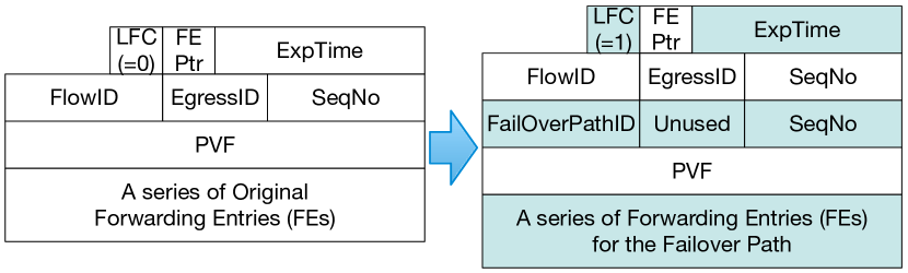
Figure 4 shows how a switch changes the packet header of an ill-fated packet when a failover path is used. The FEs of the original path are replaced with those of the failover path. Furthermore, the switch changes the expiration time field with and appends the information of the failover path (i.e., , ) below that of the original path. Hence, the packet contains the flow information of the original and the failover paths followed by the FEs of the failover path.
Then, the switch resets FE Ptr to one so that the next-hop switch on the failover path can correctly determine the FE that it needs to examine.
Lastly, the switch increments the LFC by one to indicate that a link-failure has occurred. The LFC field counts the number of failover paths that a packet has taken and enables multiple link failures to be handled without additional complexity.
Forwarding Procedure
Three changes are made to the forwarding procedure to accommodate link failures. First, since additional forwarding information is inserted into the packet if there is a detour, a switch identifies the correct FE by computing the following byte offset from the beginning of the SDNsec packet header: bytes. Second, when computing the PVF, the switch uses Equation 3 if there is a detour. is determined by looking at the FlowID field of the most recent forwarding information, which is identified by taking the byte offset of bytes.
| (3) |
4.2.2 Path Validation
Path validation accounts for the switches on the original path and the failover path. The controller obtains the switches of the path that the packet should have traversed by referring to the FlowID field(s) of the forwarding information in the header. Then using Equation 2 for the original path and Equation 3 for the failover path(s), the controller computes the expected PVF value and compares it with the PVF value in the packet header.
4.3 Multicast/Broadcast
We describe our design for multicast/broadcast forwarding that adheres to the three requirements for SDNsec (update consistency, path enforcement, and path validation). For simplicity, we refer to multicast/broadcast forwarding as multicast.
A strawman’s solution for multicast is to leverage unicast forwarding: the ingress switch replicates each packet of a multicast group and uses the unicast forwarding mechanism to send it to every egress switch that is on the path of a receiving host. This approach comes with two benefits: all three requirements are satisfied; and the unicast forwarding mechanism can be used without modifications. However, this solution is inefficient with respect to bandwidth overhead.
An alternative approach to implement multicast is to encode the multicast tree in the packet. Bloom filters can be used to efficiently encode the links of the tree [22]. For each link, the switch checks if the bloom filter returns a positive answer and forwards the packet along the corresponding links. However, the false positives of Bloom filters become a limitation: loops can be formed; and more importantly, forwarding a packet to an incorrect switch violates network isolation.
We thus adopt a stateful multicast distribution tree to forward multicast traffic. To implement forwarding along the specified tree, the forwarding decisions are stored in forwarding tables at switches. A multicast tree is represented by a two-tuple: an integer that identifies the tree (TreeID) and an expiration time (ExpTime) that indicates when the tree becomes invalid.
The controller computes a multicast tree and assigns it a unique TreeID. Then, it sends to each switch on the tree the two-tuple and the list of egress interfaces. Upon receiving a multicast packet, the ingress switch determines the correct multicast tree (based on the packet’s information) and inserts the TreeID, ExpTime, and a sequence number (SeqNo) in the packet (Figure 5). Each core switch that receives a multicast packet, looks up the forwarding information based on the TreeID in the packet and forwards it according to the list of specified interfaces.
The main challenge with this stateful approach is policy consistency, i.e., ensuring that a packet is not forwarded by two different versions of a multicast tree. To this end, we require that a tree is never updated, instead a new tree is created. However, this alone is not sufficient to guarantee drop freedom: if the ingress switch forwards packets of a newly created tree while core switches are being updated, then the packets with the new TreeID may get dropped by core switches.
To solve the problem, we add a safe-guard when switches are updated with a new multicast tree: an ingress switch is not allowed to use the new tree, i.e., insert the TreeID into incoming packets, until all other switches on the tree (core and egress switches) have been updated with the new tree information. Ingress switches can use the new tree only after an explicit notification by the controller.
Path enforcement is implemented implicitly, since only switches on the multicast tree learn the two-tuple information of the tree; packets with unknown TreeIDs are dropped. Hence, if a malicious switch incorrectly forwards a packet to an incorrect next-hop switch, then the switch will drop the packet. Tampering with the TreeID in the packet is detected through path validation.
The path validation information for multicast is similar to unicast forwarding. Each switch on the tree computes a MAC for the PVF using its shared key with the controller. The only difference is that the TreeID, instead of the FlowID, becomes an input to the MAC (Equation 4).
| (4) |
4.4 Monitoring
Network monitoring is an essential tool for traffic engineering and security auditing. For instance, network operators can steer traffic away from traffic hot spots or identify switches that drop packets.
In SDNsec, monitoring is performed at the granularity of a flow, similar to OpenFlow. Switches maintain a monitoring table that stores packet counters for the flows that they serve. Specifically, ingress switches have flow tables to look up the FEs, hence, an additional field is required for packet counters. Core switches need an additional data structure to accommodate flow statistics.
Designing monitoring for the core network is based on two principles. First, to prevent state exhaustion attacks the controller instructs switches explicitly which flows they should monitor. Since switches do not monitor all flows, an attacker cannot generate flows randomly to exhaust the monitoring table. Second, to minimize the impact of monitoring on forwarding performance, we use an exact match lookup table: the FlowID in the packet header serves as the key to the entry. Avoiding more heavyweight lookups (e.g., longest prefix matching) that require multiple memory accesses and often linear search operations (e.g., flow-table lookups in software switches) mitigates attacks that target the computational complexity of the lookup procedure.
5 Security Analysis
We start by justifying our design choice of short MACs, and then we describe how SDNsec protects from the attacks described in Section 2.1.
5.1 On the length of MACs
The path enforcement and path validation mechanisms require MAC computations and verifications at every switch. We argue that the length of the MACs – 7 bytes for FEs and 8 bytes for the PVF – is sufficient to provide the security guarantees we seek.
The main idea is that the secret keys used by other switches are not known to the attacker, which means that an attacker can at best randomly generate MACs without a way to check their validity. Consequently, the attacker would have to inject an immense amount of traffic even for a single valid FE ( attempts are required). Furthermore, to forge FEs for hops requires attempts, which becomes computationally infeasible even for . Hence, such traffic injection with incorrect MACs is easily detectable.
5.2 Path Deviation Attacks
Path deviation attacks – in which packets follow a path not authorized by the controller – can take different forms, as described in Section 2.1.
The security properties of chained MACs with respect to path validation have been formalized and verified for a decentralized setting [23]. The centralized control in SDN simplifies key management, since the controller sets up the shared symmetric keys with the switches; sophisticated key-establishment protocols are not needed. However, an important difference is that we consider the ingress and egress switch – not the hosts – as the source and destination, respectively. In Section 7, we discuss the security implications of this decision.
Path enforcement is the first line of defense against path deviation attacks. It prevents path forging and path detours from a malicious switch that generates forged FEs. The next benign switch on the path will drop the packet due to a MAC verification failure. However, a more sophisticated attacker can replay forwarding information of other paths that it is part of, but which are not authorized for the diverted flow.
Path validation is the second line of defense against path deviation attacks. Since each switch is inscribing a MAC value in the packet, the packet carries information about the presence or absence of switches on the path. The controller can reactively inspect this information and obtain a guarantee about the traversed switches and their order. SDNsec provides this guarantee because the attacker does not possess the secret keys of other switches. Note that path validation also catches attacks from malicious ingress switches that embed in the packets FEs of other flows. The controller knows the forwarding information for every flow (based on the flow tuple) and can detect the misbehavior. Changing the information that defines a flow would break communication between the end hosts; Section 7 discusses such cases in more detail.
Furthermore, sequence numbers are used to prevent replay of the path validation information. A malicious switch could replace the PVF value in a packet with a value from a previously seen packet, obfuscating the actual path taken by the packet to avoid being detected by the controller. The replay is detected through a high repetition frequency of certain sequence numbers; under normal operation each sequence number would appear at most a few times (Section 4.1).
The path enforcement and validation properties of SDNsec can be compromised in the case of multiple adjacent malicious switches. For example, if a malicious on-path switch has multiple malicious adjacent switches (not on the path), then the packets can be forwarded along the malicious path segment and back. The on-path malicious switch can then reinject the packets along the initial intended path; this attack cannot be detected, as pointed out by prior work [23].
5.3 Denial-of-Service
Network devices typically store state (e.g., forwarding tables) on fast memory (e.g., SRAM), which is a limited resource. This becomes the target of attackers by populating the memory with bogus data that replaces legitimate information.
In SDNsec, the state exhaustion attack vector is confined to the edge of the network. Only edge switches keep forwarding tables and thus they are susceptible to a state exhaustion attack by malicious hosts that originate bogus flows. Core switches keep forwarding state only for broadcast/multicast traffic, but these entries are preconfigured by the controller with the valid tree IDs and, thus, cannot be populated with bogus entries. In Section 6.3.2, we compare the performance between an edge switch and a core switch under a state exhaustion attack.
Furthermore, each switch keeps state to monitor forwarded traffic at the granularity of flows. An attacker could generate random flow IDs in order to exhaust the monitoring table. This resource is protected by having the switches monitor only flow IDs that the controller mandates. Thus, the controller can securely adapt the resources according to the device’s capabilities.
6 Implementation and Evaluation
We implement the SDNsec data-plane functionality on a software switch, and evaluate performance on a commodity server machine. Furthermore, we analyze the path validation and bandwidth overhead for the network.
6.1 Software Switch Prototype
To achieve high performance, our implementation leverages the Data Plane Development Kit (DPDK) [24] and the Intel AES-NI instruction set [25]. DPDK is an open-source set of libraries and drivers for packet processing in user space. DPDK comes with zero-copy Network Interface Card (NIC) drivers that leverage polling to avoid unnecessary interrupts. Intel AES-NI is an instruction set that uses hardware cryptographic engines built into the CPU to speed up the AES block cipher.
To compute and verify the required MACs, we use the Cipher Block Chaining mode (CBC-MAC) with AES as the block cipher. The input lengths to the MACs for a FE and PVF are 15 and 14 bytes respectively. Note that for both cases the input fits in one AES block (16 bytes) and that the input length is fixed and independent of the path length555CBC-MAC is vulnerable when used for variable-length messages. Furthermore, we use 128-bit encryption keys and truncate the output to the required number of bits (Section 4.1).
Furthermore, we optimize forwarding in the following ways. First, we store four FEs in different xmm registers (xmm0-xmm3) and issue four encryption instructions with the preloaded round key (stored in xmm4). Since each AES engine can simultaneously perform 4 AES operations, a switch can process four packets in parallel on each CPU core. The assembly code snippet is given below:
aesenc xmm0,xmm4 //Round 1 for Packet 1
aesenc xmm1,xmm4 //Round 1 for Packet 2
aesenc xmm2,xmm4 //Round 1 for Packet 3
aesenc xmm3,xmm4 //Round 1 for Packet 4
Second, a dedicated CPU core is assigned to a NIC port and handles all the required packet processing for the port. Each physical core has a dedicated AES-NI engine and thus packets received on one port are served from the AES-NI engine of the physical core assigned to that port.
Third, we create per-core data structures to avoid unnecessary cache misses. Each NIC is linked with a receive queue and a transmit queue, and these queues are assigned to a CPU core to handle the NIC’s traffic. Furthermore, we load balance traffic from one NIC over multiple cores, depending on the system’s hardware. For this purpose, we leverage Receiver Side Scaling (RSS) [26] as follows: each NIC is assigned multiple queues, and each queue can be handled by another core. RSS is then used to distribute traffic among the queues of a NIC.
Our implementation of the edge switch is based on the DPDK vSwitch [27]. The DPDK vSwitch is a fork of the open source vSwitch [28] running on DPDK for better performance. Open vSwitch is a multilayer switch that is used to build programmable networks and can run within a hypervisor or as a standalone control stack for switching devices. Edge switches in SDNsec use the typical flow matching rules and forwarding tables to forward a packet and therefore we chose to augment an existing production quality solution. We augment the lookup table to store forwarding information for a flow in addition to the output port. The ingress switch increases the size of the packet header and inputs the additional information (FEs, sequence number, and its PVF).
We implement core switches from scratch due to the minimal functionality they perform. A core switch performs two MAC computations (it verifies its FE and computes its PVF value), updates the flow’s counters (if the flow is monitored), and forwards the packet from the specified port.
6.2 Packet Overhead
The security properties of SDNsec come at the cost of increased packet size. For each packet, the ingress switch creates an additional packet header with its size depending on the path length: 8 bytes/switch (including the egress switch) and a constant amount of 22 bytes/packet.
To put the packet overhead into context, we analyze two deployment scenarios for SDNsec: a data-center deployment and a research network deployment. Furthermore, to evaluate the worst case for SDNsec, we consider the diameter of the network topologies, i.e., the longest shortest path between any two nodes in the network. We also evaluate the packet overhead for the average path length in the research-network case.
| Packet Size | ||||
|---|---|---|---|---|
| 200 B | 850 B | 1400 B | ||
| Leaf-Spine | 19.0% | 4.5% | 2.7% | |
| 3-Tier | 27.0% | 6.4% | 3.9% | |
For the data-center case, we consider two common data center topologies: a leaf-spine topology [29] and a 3-tier topology (access, aggregation, and core layer) [30]. The diameter for the leaf-spine topology is 4 links (i.e., 3 switches) and for the 3-tier topology 6 links (i.e., 5 switches)666Our reported path lengths include the links between the hosts and the switches.. In addition, to relate the overhead to realistic data center traffic, we use the findings of two studies: the average packet size in data centers is 850 bytes [20], and packet sizes are concentrated around the values of 200 and 1400 bytes [21]. Table 1 shows the overhead for the different topologies and path lengths.
| Trace 1 | Trace 2 | Trace 3 | ||||
| 747 B | 463 B | 906 B | 1420 B | 691 B | 262 B | |
| A | 8.3% | 13.4% | 6.8% | 4.4% | 9.0% | 23.7% |
| D | 12.6% | 20.3% | 10.4% | 6.6% | 14.0% | 35.9% |
For the research network deployment, we analyze the topology of the Internet2 network [31], which is publicly available [32]; we consider only the 17 L3 and 34 L2 devices in the topology – not the L1 optical repeaters – and find a diameter of 11 links (i.e., 10 switches). Furthermore, for the Internet2 topology we calculate an average path length of 6.62 links (i.e., 6 switches). To relate the overhead to actual traffic, we analyze three 1-hour packet traces from CAIDA [33] and calculate the respective packet overhead for the mean and median packet lengths. (Table 2).
Our results indicate a moderate packet overhead for the average path length in Internet2 and a considerable packet overhead for the worst case (high path lengths) in both deployment scenarios. This analysis provides an insight about the price of security and robustness for policy enforcement and validation of the SDN data plane. Furthermore, we observe that the packet overhead is more significant for ISP topologies because they have typically longer paths than data center networks: data center networks are optimized with respect to latency and cabling length leading to shorter path lengths. Novel data center topologies demonstrate even shorter path lengths compared to the more common topologies we analyzed [34]. This path-length optimization leads to a lower packet overhead for a data center deployment of SDNsec.
6.3 Performance Evaluation
We compare the forwarding performance of edge and core switches with the DPDK vSwitch under two scenarios: normal operation and a state exhaustion attack.
We run the SDNsec software switch on a commodity server machine. The server has a non-uniform memory access (NUMA) design with two Intel Xeon E5-2680 CPUs that communicate over two QPI links. Each NUMA node is equipped with four banks of 16 GB DD3 RAM. Furthermore, the server has 2 dual-port 10 GbE NICs (PCIe Gen2x8) providing a unidirectional capacity of 40 Gbps.
We utilize Spirent SPT-N4U-220 to generate traffic. We specify IPv4 as the network-layer protocol, and we vary Ethernet packet sizes from 128 to 1500 bytes.777We exclude 64-byte packets because the minimum packet size in the core of the network is higher because the additional information in SDNsec does not fit in the minimum-sized Ethernet packet. For a given link capacity, the packet size determines the packet rate and hence the load on the switch. For example, for 128-byte packets and one 10 GbE link, the maximum packet rate is 8.45 Million packets per second (Mpps); for all 8 NIC ports it is 67.6 Mpps. These values are the physical limits and represent the theoretical peak throughput.
Furthermore, for the SDNsec edge switch and the DPDK vSwitch, we populate a flow table with 64k entries; for the SDNsec edge switch, the flow table holds forwarding entries for a path with 5 switches. Flows are defined based on the destination MAC address – all other fields remain constant.
6.3.1 Normal Operation
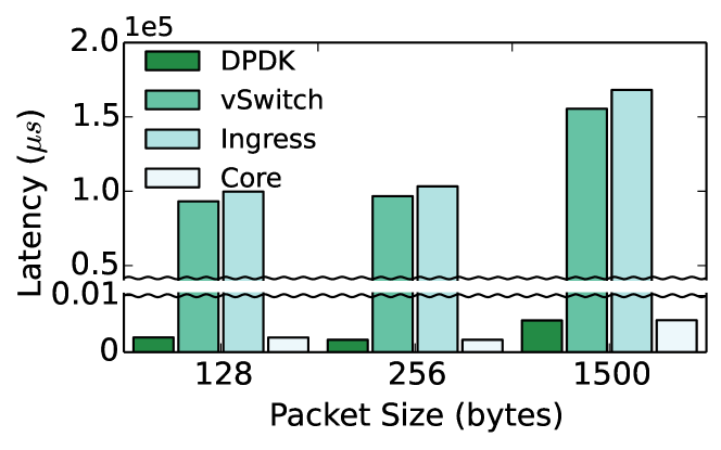
For normal operation, we generate packets with a destination MAC address in the range of the addresses stored in the flow table of the switch. Figure 6(b) shows the average latency per packet, and Figure 6(a) shows the switching performance for a 60-second measurement interval.
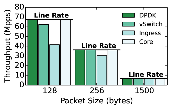
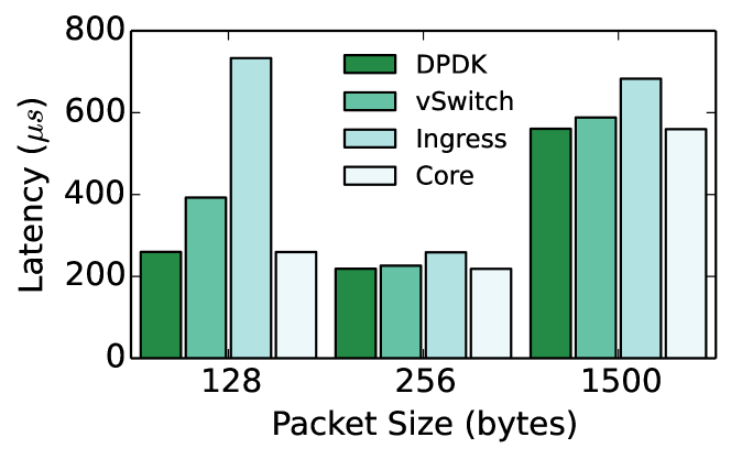
The ingress switch demonstrates a higher latency compared to DPDK vSwitch because the SDNsec header must be added to every packet: the packet size increases and the longer entries in the lookup table cause additional cache misses that increase latency. Furthermore, the latency of the core switch is the same as the DPDK baseline latency, demonstrating the minimal processing overhead at the core switches.
We observe a considerable performance decrease for the ingress switch compared to the DPDK vSwitch. This decrease is a side-effect of the packet overhead (Section 6.2): the outgoing traffic volume of an ingress switch is higher than the incoming volume. Thus, when the incoming links are fully utilized, packets get dropped and the throughput is lower (assuming that the aggregate ingress and egress capacity of the switch is the same). This comparison captures the effect of packet overhead and not the processing overhead. In contrast to the ingress switch, the core switch outperforms the other switches and achieves the baseline performance for all packet sizes.
Our experiments under normal operation demonstrate a performance decrease at the edge of the network, however, the core of the network can handle significantly more traffic, compared to today’s SDN realization.
6.3.2 State Exhaustion Attack
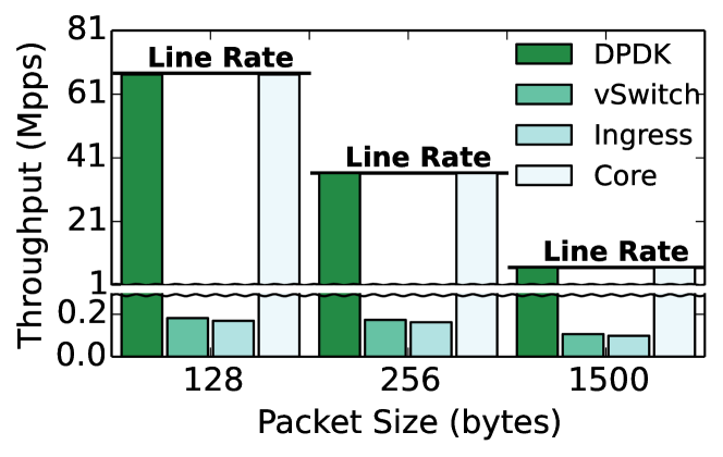
To analyze the switching performance of the switch under a state exhaustion attack, we generate traffic with random destination MAC addresses. The destination addresses are randomly drawn from a pool of (4 billion) addresses to prevent the switches from performing any optimization, such as caching flow information. Figure 7 shows the switching performances.
We observe a considerable decrease (i.e., over 100 times slower than the DPDK baseline) in throughput for both the DPDK vSwitch and the ingress switch (Figure 7(a)). This decrease is due to cache misses when performing flow table lookups–the switches are forced to perform memory lookups, which are considerably slower than cache lookups, in order to determine the forwarding information to process the incoming packets. The latency plot in Figure 7(b) tells a similar story: both the DPDK vSwitch and the ingress switch take considerably longer time to process packets.
However, for the core switches the switching performance remains unaffected compared to normal operation. This is because the core switches do not perform any memory lookup when processing packets.
6.4 Path Validation Overhead
Path validation introduces processing overhead for the controller and bandwidth overhead for the network. The controller has to recompute the PVFs for the reported packets, and the egress switches have to report the PVFs in the packet headers to the controller.
We estimate the overheads based on information for large data centers: 80k hosts [35] with 10G access links that are utilized at 1% (in each direction) [36] and send average-sized packets of 850 bytes [data_traffic]. Due to lack of knowledge for traffic patterns, we consider the worst case: all traffic is inter-rack and the path consists of 5 switches (worst-case path length for 3-tier data center); also, all egress switches report all the packet headers. Overall, the aggregate packet rate for this setup is 1176 Mpps.
We implement the PVC, which reads the packet headers, fetches the corresponding shared keys with the switches, and recomputes the PVFs. For the previous setup, an 8 core CPU can validate 17 Mpps. For the whole data-center traffic (1176 Mpps), 69 CPUs would be required.
For the bandwidth overhead, the data size to validate one packet is 14 bytes (3 bytes for the FlowID, 3 bytes for the SeqNo, and 8 bytes for the PVF). For the previous setup, we estimate the bandwidth overhead at 115 Gbps, which accounts for 1.6% of the whole data-center traffic.
7 Discussion
One attack we have not considered is packet dropping by a malicious switch. Flow statistics through monitoring provide a basic defense perimeter for such attacks. The controller can instruct switches to periodically report packet counters for certain flows and then inspect if packets are dropped at a certain link. Furthermore, dishonest reports would result in inconsistent reports that pinpoint the misbehavior to a certain link between two switches (it is not possible to identify the exact switch) [37]. However, packet dropping from a malicious ingress or egress switch cannot be detected through monitoring. This is the side-effect of a design decision in SDNsec.
We have made the deliberate design decision that the network stack of the host should not be modified. This design choice provides a smoother incremental deployment path for SDNsec, since hosts do not perform any additional functionality. This can be beneficial also for a data-center deployment, when tenants have control over their operating system (e.g., in the Infrastructure-as-a-Service model).
This design decision, however, has implications for the security properties of SDNsec and enables certain attacks. For example, a malicious egress switch can transfer packets out of an incorrect interface, replay packets, or drop packets; without feedback from the end host it is not possible to detect such attacks. Furthermore, a malicious ingress switch can replay packets without being detected, since the ingress switch can inscribe different sequence numbers; again, the transport layer of the destination host – and not the network – can detect the replay.
8 Related Work
We briefly describe recent research proposals that are related to data-plane security and state reduction in SDN.
Data-plane security
There are only a few proposals accounting for compromised switches at the data plane. The most closely related work to ours is SANE [12]: the controller hands out capabilities to end hosts – not to switches, as in SDNsec – in order to enforce network paths. This approach requires modification of end hosts in order to perform additional tasks. Namely, every host must communicate with the controller in order to establish a shared symmetric key and obtain capabilities. Failure recovery is pushed to the host, which has to detect the failure and then explicitly ask the controller for a new path. In addition, SANE cannot provide protection against stronger adversaries that collude and perform a wormhole attack: a malicious switch can replay capabilities by prepending them to the existing forwarding information in the packet and thus can diverge traffic over another path; a colluding switch removes the prepended capabilities and forwards packets to a downstream switch of the original path. SDNsec provides path validation to deal with such attacks. Finaly, SANE does not consider broadcast/multicast forwarding.
Jacquin et al.[38] take another approach, using trusted computing to attest remotely that network elements use an approved software version. Being a first step in this direction, there are unaddressed challenges with respect to scalability: processing overhead (overall attestation time), bandwidth overhead (extra traffic due to attestation), and management overhead (the number of different software versions deployed).
OPT [39] provides path validation on top of a dynamic key-establishment protocol that enables routers to re-create symmetric keys with end hosts. In SDNsec, key management is simplified, since each router shares a key only with the controller. Thus, we do not involve the host in any key establishment and avoid the overhead of key establishment in the presented protocols.
ICING [40] is another path validation protocol that leverages cryptographic information in the packets. Each router on the path verifies cryptographic markings in the packet that were inserted by the source and each upstream router. ICING comes with a high bandwidth overhead due to large packet sizes, demonstrating a 23.3% average packet overhead. Furthermore, ICING requires pairwise symmetric keys between all entities on a path.
State reduction for SDN
Another class of proposals focuses on state reduction for the SDN data plane. Source routing is a commonly used approach to realize this goal, and recent work shows that source routing not only decreases the forwarding table size, but provides a higher and more flexible resource utiliziation [41]. In SourceFlow [42], packets carry pointers to action lists for every core switch on the path. Hence, core switches only store action tables that encode potential actions for packets and are indexed by a pointer in the packet. Segment Routing [43] is based on source routing and combines the benefits of MPLS [44] with the centralized control of SDN. An ingress switch adds an ordered list of instructions into the packet header, and each subsequent switch inspects such an instruction. These approaches are similar to SDNsec in that they reduce state at core switches by embedding information in packet headers. However, the use of source routing without corresponding security mechanisms opens a bigger attack vector compared to legacy hop-by-hop routing: a single compromised switch can modify the forwarding information and steer a packet over a non-compliant path.
9 Conclusion
Security in SDN remains a neglected issue and could raise deployment hurdles for security concerned environments. We have presented a security extension to achieve forwarding accountability for the SDN data plane, i.e., to ensure that the operator’s policies are correctly applied to the data plane. To this end, we have designed two mechanisms: path enforcement to ensure that the switches forward the packets based on the instructions of the operator and path validation to allow the operator to reactively verify that the data plane has followed the specified policies. In addition, SDNsec guarantees consistent policy updates such that the behavior of the data plane is well defined during reconfigurations. Lastly, minimizing the amount of state at the core switches confines state exhaustion attacks to the network edge. We hope that this work assists in moving towards more secure SDN deployments.
References
- [1] N. McKeown, T. Anderson, H. Balakrishnan, G. Parulkar, L. Peterson, J. Rexford, S. Shenker, and J. Turner, “OpenFlow: Enabling Innovation in Campus Networks,” SIGCOMM Comput. Commun. Rev., 2008.
- [2] S. Shin, P. A. Porras, V. Yegneswaran, M. W. Fong, G. Gu, and M. Tyson, “FRESCO: Modular Composable Security Services for Software-Defined Networks.” in Proc. of NDSS, 2013.
- [3] A. Khurshid, W. Zhou, M. Caesar, and P. B. Godfrey, “VeriFlow: Verifying Network-wide Invariants in Real Time,” in Proc. of ACM HotSDN, 2012.
- [4] P. Porras, S. Shin, V. Yegneswaran, M. Fong, M. Tyson, and G. Gu, “A Security Enforcement Kernel for OpenFlow Networks,” in Proc. of HotSDN, 2012.
- [5] “Cisco Routers Compromised by Malicious Code Injection,” "http://bit.ly/1KtUoTs", Sep. 2015.
- [6] “Juniper ScreenOS Authentication Backdoor,” "http://bit.ly/1Nx8J5i", Dec. 2015.
- [7] “Snowden: The NSA planted backdoors in Cisco products,” "http://bit.ly/1PKtbQW", May 2015.
- [8] P.-W. Chi, C.-T. Kuo, J.-W. Guo, and C.-L. Lei, “How to Detect a Compromised SDN Switch,” in Proc. of IEEE NetSoft, 2015.
- [9] R. Kloti, V. Kotronis, and P. Smith, “OpenFlow: A Security Analysis,” in Proc. of IEEE NPSec, 2013.
- [10] M. Antikainen, T. Aura, and M. Särelä, “Spook in Your Network: Attacking an SDN with a Compromised OpenFlow Switch,” in Secure IT Systems, 2014.
- [11] M. Reitblatt, N. Foster, J. Rexford, C. Schlesinger, and D. Walker, “Abstractions for Network Update,” in Proc. of ACM SIGCOMM, 2012.
- [12] M. Casado, T. Garfinkel, A. Akella, M. J. Freedman, D. Boneh, N. McKeown, and S. Shenker, “SANE: A Protection Architecture for Enterprise Networks,” in Proc. of USENIX Security, Aug 2006.
- [13] P. Kazemian, G. Varghese, and N. McKeown, “Header Space Analysis: Static Checking for Networks,” in Proc. of USENIX NSDI, 2012.
- [14] P. Kazemian, M. Chang, H. Zeng, G. Varghese, N. McKeown, and S. Whyte, “Real Time Network Policy Checking Using Header Space Analysis,” in Proc. of USENIX NSDI, 2013.
- [15] H. Mai, A. Khurshid, R. Agarwal, M. Caesar, P. B. Godfrey, and S. T. King, “Debugging the data plane with anteater,” in Proc. of ACM SIGCOMM, 2011.
- [16] “IEEE Standard for Local and metropolitan area networks - Port-Based Network Access Control,” IEEE Std 802.1X-2004, Dec 2004.
- [17] R. Mahajan and R. Wattenhofer, “On Consistent Updates in Software Defined Networks,” in Proc. of ACM HotNets, 2013.
- [18] X. Jin, H. H. Liu, R. Gandhi, S. Kandula, R. Mahajan, M. Zhang, J. Rexford, and R. Wattenhofer, “Dynamic Scheduling of Network Updates,” in Proc. of ACM SIGCOMM, 2014.
- [19] O. N. Foundation, “OpenFlow Switch Specification Version 1.5.0,” "http://bit.ly/1Rdi6Yg", 2014.
- [20] T. Benson, A. Anand, A. Akella, and M. Zhang, “Understanding Data Center Traffic Characteristics,” SIGCOMM Comput. Commun. Rev., 2010.
- [21] T. Benson, A. Akella, and D. A. Maltz, “Network Traffic Characteristics of Data Centers in the Wild,” in Proc. of ACM IMC, 2010.
- [22] P. Jokela, A. Zahemszky, C. Esteve Rothenberg, S. Arianfar, and P. Nikander, “LIPSIN: Line Speed Publish/Subscribe Inter-networking,” in Proc. of ACM SIGCOMM, 2009.
- [23] F. Zhang, L. Jia, C. Basescu, T. H.-J. Kim, Y.-C. Hu, and A. Perrig, “Mechanized Network Origin and Path Authenticity Proofs,” in Proc. of ACM CCS, 2014.
- [24] “Data Plane Development Kit,” "http://dpdk.org".
- [25] S. Gueron, “Intel Advanced Encryption Standard (AES) New Instructions Set ,” 2012.
- [26] S. Goglin and L. Cornett, “Flexible and extensible receive side scaling,” 2009.
- [27] “Open vSwitch accelerated by DPDK,” "https://github.com/01org/dpdk-ovs".
- [28] “Open vSwitch,” "www.openvswitch.org".
- [29] M. Alizadeh and T. Edsall, “On the Data Path Performance of Leaf-Spine Datacenter Fabrics,” in Proc. of IEEE HOTI, 2013.
- [30] Cisco, “Data Center Multi-Tier Model Design,” "http://bit.ly/23vtt5u".
- [31] “Internet2,” "https://www.internet2.edu".
- [32] “Internet2 Network NOC,” "http://bit.ly/1JHulh0".
- [33] “CAIDA: Center for Applied Internet Data Analysis,” "http://www.caida.org".
- [34] A. Singla, C.-Y. Hong, L. Popa, and P. B. Godfrey, “Jellyfish: Networking Data Centers Randomly,” in Proc. of USENIX NSDI, 2012.
- [35] “Inside Amazon’s Cloud Computing Infrastructure,” "http://bit.ly/1JHulh0", 2015.
- [36] A. Roy, H. Zeng, J. Bagga, G. Porter, and A. C. Snoeren, “Inside the social network’s (datacenter) network,” in Proceedings of the 2015 ACM Conference on Special Interest Group on Data Communication.
- [37] S. Goldberg, D. Xiao, E. Tromer, B. Barak, and J. Rexford, “Path-quality Monitoring in the Presence of Adversaries,” in Proc. of ACM SIGMETRICS, 2008.
- [38] L. Jacquin, A. Shaw, and C. Dalton, “Towards trusted software-defined networks using a hardware-based Integrity Measurement Architecture,” in Proc. of IEEE NetSoft, 2015.
- [39] T. H.-J. Kim, C. Basescu, L. Jia, S. B. Lee, Y.-C. Hu, and A. Perrig, “Lightweight Source Authentication and Path Validation,” in Proc. of ACM SIGCOMM, 2014.
- [40] J. Naous, M. Walfish, A. Nicolosi, D. Mazières, M. Miller, and A. Seehra, “Verifying and Enforcing Network Paths with ICING,” in Proc. of ACM CoNEXT, 2011.
- [41] S. A. Jyothi, M. Dong, and P. B. Godfrey, “Towards a Flexible Data Center Fabric with Source Routing,” in Proc. of ACM SOSR, 2015.
- [42] Y. Chiba, Y. Shinohara, and H. Shimonishi, “Source Flow: Handling Millions of Flows on Flow-based Nodes,” in Proc. of ACM SIGCOMM, 2010.
- [43] “Segment Routing Architecture,” "https://tools.ietf.org/html/draft-filsfils-rtgwg-segment-routing-01".
- [44] E. Rosen, A. Viswanathan, and R. Callon, “Multiprotocol Label Switching Architecture,” RFC 3031 (Proposed Standard), Internet Engineering Task Force, Jan. 2001.