A decoherence-free subspace in a charge quadrupole qubit
Abstract
Quantum computing promises significant speed-up for certain types of computational problems. However, robust implementations of semiconducting qubits must overcome the effects of charge noise that currently limit coherence during gate operations. Here, we describe a scheme for protecting solid-state qubits from uniform electric field fluctuations by generalizing the concept of a decoherence-free subspace for spins, and we propose a specific physical implementation: a quadrupole charge qubit formed in a triple quantum dot. The unique design of the quadrupole qubit enables a particularly simple pulse sequence for suppressing the effects of noise during gate operations. Simulations yield gate fidelities 10-1000 times better than traditional charge qubits, depending on the magnitude of the environmental noise. Our results suggest that any qubit scheme employing Coulomb interactions (e.g., encoded spin qubits or two-qubit gates) could benefit from such a quadrupolar design.
Due to the fragility of quantum information, multiple layers of error suppression will be needed for any scalable implementation of a quantum computerLidar2003 . Active suppression methods include quantum error correctionMerminBook and composite pulse sequencesKhodjasteh2009 ; West2010 ; Wang2012 ; Kestner2013 , while passive strategies include forming decoherence-free subspaces or subsystemsPalma1996 ; Duan1998 ; Zanardi1997 ; Lidar1998 ; Knill2000 (DFS), and optimal working pointsVion2002 (“sweet spots”). DFS are particularly attractive, because of their minimal overhead requirements. Previous proposals for DFS in quantum dots have focused on spin qubits and the decoherence caused by uniform magnetic field fluctuations, Kempe2001 . For example, if is a spin operator for the th qubit, then the fluctuation Hamiltonian is given by , where is the Landé -factor and is the Bohr magneton. A DFS then corresponds to a logical encoding of the qubit for which both states are equally affected by the fluctuation.
Unfortunately, recent experiments suggest that the dominant noise source for spin qubits is electric field noiseDial2013 (“charge noise”), which rapidly degrades the quantum coherence when the spins are coupled via exchange interactionsLoss1998 , or effectively transformed into charge qubitsHayashi2003 ; Petersson2010 via spin-to-charge conversion, as in proposals for two-qubit gatesTaylor2005 . The Hamiltonian for a uniform electric field fluctuation acting on an array of charges takes the form , where the position operator for the th electron, , plays an explicit role for charge fluctuations, in contrast to magnetic fluctuations. This position dependence for uniform electric fields is quite different than the case for spins interacting with a uniform (global) magnetic field, suggesting that it could be impossible to form a DFS for charge qubits, or spin qubits that exploit the charge sector. Recent efforts to suppress the effects of charge noise in quantum dots have therefore focused on sweet spots, which typically occur at energy level anticrossings, and suppress the leading order effects of Petersson2010 ; Kim2014 ; Brandur .
In this paper, we show that, contrary to expectations, certain dot geometries do support a DFS for charge. To make the discussion concrete, we propose a new type of charge qubit that we call a charge quadrupole (CQ). Our scheme embraces both passive and active noise suppression strategies: symmeties incorporated into the qubit design naturally suppress the effects of uniform electric field fluctuations (passive), while the special form of the Hamiltonian enables dynamical decoupling sequences (active) that are shorter than existing protocols for quantum gate operations. We provide an analytical explanation for the suppression of dephasing within the logical subspace. We also perform simulations that yield substantial improvements in gate fidelities by combining passive and active error suppression, under realistic assumptions about the charge noise. We further propose extensions of the quadrupolar geometry for coupling a charge qubit to a microwave cavity or to another qubit.
Results
Decoherence-free subspace. Before describing the CQ qubit in detail, we first recall a DFS for spins. Three spins can encode a DFS that protects against arbitrary uniform magnetic field fluctuationsDiVincenzo2000 ; DeFilippo2000 ; Yang2001 , . The DFS consists of two states with the same values of the total spin along the quantization axis, , and of the total spin . The DFS has two important properties: first, the difference in the energies of the two qubit states is independent of magnetic field, and second, changing a spin-independent Hamiltonian causes the system to evolve only between the qubit states; non-qubit (“leakage”) states cannot be accessed because they are not coupled to the qubit states by the Hamiltonian.
Here we construct a similar arrangement for charge states that protects against uniform electric field variations. All linear superpositions of the logical states must have the same total charge and also the same center of mass, so that the contribution to the energy from a uniform field, , is the same for all qubit states. In addition, it is important that the system Hamiltonian does not couple the qubit states to the other states in the full Hilbert space. These conditions are satisfied if the Hamiltonian conserves charge and has an appropriate symmetry: the qubit logical states should have the same total charge and be eigenstates of a symmetry operator with the same eigenvalue. An appropriate candidate geometry is a central dot that is symmetrically coupled to a set of outer dots having the same center of mass as the center dot, even under permutation. Analogous to the situation for a spin DFSDeFilippo2000 ; Lidar2003 , the symmetry constraints cannot be satisfied in a two-dimensional (double-dot) code space; the smallest device that can support a charge DFS is a triple dot.
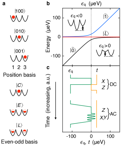
Charge quadrupole qubit. Here we consider a linear triple dot geometry, where the symmetry operation is the permutation operator between the outer two dots, , which is equivalent to reflection about the center. It is convenient to adopt the basis states , where and refer to “center” and “even.” The resulting eigenvalue is , corresponding to even symmetry. The third, orthogonal state, , has eigenvalue , corresponding to odd symmetry, and generates a dipole that couples to charge fluctuations when superposed with . When the symmetry constraint is satisfied, the even and odd manifolds decouple.
The logical charge states of a CQ qubit are protected from uniform electric field fluctuations because their charge distributions have the same center of mass (in other words, no dipole moment). It is interesting to note that several related systems also propose to use dipole-free geometries, including the zero-detuning sweet spot of a conventional charge qubitPetersson2010 ; Shi2013 ; Kim2015 , which we analyze below, a three-island transmon qubitGambetta2011 , and quantum cellular automataOi2005 ; Hentschel2007 ; Bayat2015 .
We now examine the CQ qubit in more detail. We consider a triple dot with one electron, as illustrated in Fig. 1. The full Hamiltonian in the position basis is given by
| (1) |
where and are the tunneling amplitudes between neighboring dots, and , , and are site potentials. We have also defined the dipolar and quadrupolar detuning parameters, and , as
| (2) |
The eigenvalues of are plotted as a function of in Fig. 1b, where the lowest and highest energy levels correspond to the logical eigenstates and , respectively, and the middle level is the leakage state . This ordering is an uncommon but benign feature of the CQ qubit, as shown below. We note that, away from , the eigenstate differs slightly from the basis state due to mixing terms in equation (1). Below, we show that under ideal conditions, the mixing terms are small, so that .
It is instructive to compare to a conventional, one-electron charge qubit formed in a double dot, which we refer to as a charge dipole (CD):
| (3) |
In this case, is the dipole detuning, and there is no quadrupole detuning. In what follows, we express the detuning parameters in terms of their average () and fluctuating () components. Uniform electric field fluctuations are then associated with , while fluctuations of the field gradient are associated with .
Charge noise. It has been shown that phonon decoherence processes can be classified based on multipole momentsStorcz2005 . Here, we consider charge noise decoherence processes for the leading order (dipole and quadrupole) moments in the noise, which by construction we will expect to behave very differently for CD and CQ qubits. Fluctuations in are dangerous for single-qubit operations since they cause fluctuations of the energy splitting between the qubit levels, , resulting in phase fluctuations. The success of the DFS depends on our ability to engineer a triple-dot in which the dephasing effects of fluctuations are suppressed. The next-leading source of fluctuations, , is much weaker, and we show in Supplementary Note 1 that
| (4) |
where is the interdot spacing and is the characteristic distance between the qubit and the charge fluctuators that cause . We also estimate that in recent devices used for double dot qubit experimentsPetersson2010 ; Shi2013 . In Supplementary Note 2, we further show that is related to the more fundamental noise parameter (the fluctuating electric field) as , so that . Therefore, the effects of charge noise can be suppressed by making smaller through engineering, by reducing the lithographic feature size and the interdot spacing. This is one of the key attractions of the quadrupole qubit: it provides a straightforward path for systematically improving the qubit fidelity, by reducing the device size.
The Hamiltonian has four independently tunable parameters. We now determine the control settings consistent with DFS operation. Our goal is to block diagonalize so that it decomposes into a two-dimensional (2D) logical subspace, and a 1D leakage space. Any coupling to the leakage space would result in energy-level repulsions as a function of the tuning parameters. We can therefore suppress such coupling by requiring that , where is the leakage state energy, yielding the desired tunings: and . These are the same conditions obtained by requiring that , to obtain simultaneous eigenstates of and . The even-symmetry states and are good choices for basis states in the 2D manifold. With the basis set , and the parameter tunings and , we find that block diagonalizes as desired. (For notational convenience, we define .) In the logical subspace , the reduced Hamiltonian is then given by , where and are Pauli matrices.
We now compare the effects of fluctuations on the energy levels of CD and CQ qubits. (In the following sections, we explore the effect of fluctuations on gate operations.) The energy splitting of CD qubits is obtained from equation (3) as . A fluctuation expansion in powers of yields
| (5) |
The first term in equation (5) indicates that and are the main control parameters. The second term indicates that the qubit is only protected from fluctuations of at the sweet spot, . In contrast, the CQ qubit has two detuning parameters. In this case, we fix and calculate the energy splitting by writing and . Expanding in and yields
| (6) |
where we note that . By construction, has no terms of when . Moreover, we see that fluctuations of vanish when . Hence, represents a double sweet spot. Since , dephasing is minimized when we set and adopt and as the control parameters for CQ gate operations. Although does not appear at linear order in , its main effect is to cause leakage for CQ qubits, rather than dephasing — a point that we return to below. For both CD and CQ qubits, we note that increasing the tunnel coupling also suppresses the energy fluctuations, particularly near the sweet spot; this is consistent with recent results in a resonantly gated three-electron exchange-only qubitMedford2013 ; Taylor13 .
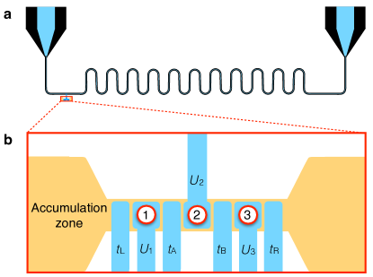
Pulsed gates for the CQ qubit. Here we investigate pulsed (DC) gates, assuming that and can be independently tuned and set to zero. We perform rotations of angle around the axis of the Bloch sphere () by setting and . Rotations of angle around the axis () are achieved by setting and . Readout is performed by measuring the charge occupation of the center dot. In fact, all external couplings to initialization and readout circuits or to other qubits should be made through the center dot, to preserve the symmetries of the qubit, as illustrated in Fig. 2.
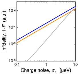
We compare gate operations in CQ qubits to those of CD qubits via simulations that include quasistatic charge noise. Results for the infidelities of simple (“bare”) rotations for CQ and CD qubits are presented in Fig. 3 (blue and orange curves, respectively), as functions of the standard deviation of charge noise fluctuations. (See Methods for details.) Both curves follow the same scaling behavior, which can be explained as follows. The effect of quasistatic noise, , may be regarded as a gating error that induces underrotations, overrotations, or rotations about a misoriented axis. For CD qubits, such errors occur within the logical Hilbert space, while for CQ qubits, the misrotation occurs primarily to the leakage state. Defining the state fidelity as , where is the actual final state and is the target state, the noise drives . For either qubit, the resulting infidelity of noisy rotations scales as . For example, the probability of a CQ qubit being projected onto its leakage state is .
Composite pulse sequences. Fortunately, time evolution remains largely coherent throughout a gate operation, so that special pulse sequences can be used to undo the leakage and suppress the errorsWang2012 ; Kestner2013 ; GhoshUnp . In ref. GhoshUnp, , three-pulse sequences were constructed for the CQ qubit, following the same control constraints indicated in Fig. 1c, which are experimentally motivated: the control parameters and can be pulsed independently, but not simultaneously, between zero and a finite value. There it was shown that special values of the control parameters can be used to cancel out the leading order effect of noise, yielding a universal set of low-leakage, single-qubit gate operations. In Fig. 3, we compare one such composite sequence for the CQ qubit, , to bare, single-step sequences for rotations in both CD and CQ qubits. The results show that significant benefits can be achieved with composite sequences: for charge noise levels consistent with recent experimentsKim2014 ; Mi2017 , fidelity improvements are in the range of 10-1000.
While noise-cancelling pulse sequences have been proposed for quantum dot spin qubitsWang2012 ; Kestner2013 , they are significantly more complex than the three-pulse sequence used in Fig. 3. Those sequences are constructed by inserting identity operations into the pulse sequence and assuming a continuous range of rotation axes in some plane of the Bloch sphere. The constraints assumed above, where and are not varied simultaneously, yield bare and rotations, but no continuous range of rotation axes. Under such conditions, no three-pulse sequence exists that can cancel out leading-order noise in CD qubits. By relaxing these constraints to allow simultaneous tuning of and – a challenging but potentially achievable goal – it becomes possible to construct a five-step sequence to cancel out the leading-order noise in CD qubits. Thus, the three-step sequence described above for CQ qubits is truly “minimal,” in the sense that it has the same level of complexity as a conventional spin-echo sequence, which has been shown to be effective for preserving the coherence of a CD qubitKim2015 .
Microwave driven gates. While it is necessary to move away from the sweet spot to perform certain microwave-driven (AC) gate operations, it is possible to center the AC signal at the sweet spot, as indicated in Fig. 1b, which improves the coherence of gate operations. Below, we analyze the AC gate sequence shown in Fig. 1b. Here, initialization and readout are performed in the far-detuned regime. However, we now consider an adiabatic ramp to the sweet spot, so that the working point defines the quantization axis in the laboratory frame. For AC gates, one typically moves to the frame rotating at the qubit frequency, where and rotations are obtained by driving the appropriate detuning parameter (dipolar for a CD qubit, quadrupolar for a CQ qubit), with the appropriate phase, at the resonance frequency .
In the rotating frame, the primary decoherence mechanism during or rotations is longitudinal, with the corresponding decay time Yan2013 . In this case, the charge noise environment is nearly Markovian, so that, on resonance, it is sufficient to use Bloch-Redfield theory, givingJing2014
| (7) |
where is the amplitude of the resonant drive, and and are the longitudinal and transverse noise spectral densities in the lab frame, respectively. These functions describe the noise in the detuning parameters used to drive the rotations ( for CD qubits, or for CQ qubits). In the weak driving regime, , the term would normally dominate equation (7) because for charge noise. However, at the sweet spot, the noise for either type of qubit is orthogonal to the quantization axis, so that . The other terms in equation (7) are relatively small, since their arguments are large.
We can compare for CD and CQ qubits by assuming that the noise terms, and , both arise from the same charge fluctuators. In this case, the ratio of their amplitudes, , is independent of the frequency and the decoherence rates for resonant and rotations in a CQ qubit are suppressed by this same ratio, as compared to a CD qubit. After applying simple pulse sequences to suppress the leakage, CQ qubits are therefore protected from the dominant () noise source for all rotation axes, for both pulsed and resonant gates, while CD qubits require a more complex correction scheme.
Spin quadrupole qubits. Up to this point, we have focused on charge qubits. However, quadrupolar geometries can also be used to protect logical spin qubits from dipolar detuning fluctuations. For example, the standard two-electron singlet-triplet (-) qubit formed in a double quantum dotLevy2002 ; Petta2005 is not protected from dipolar detuning fluctuations during implementation of an exchange gate. But a singlet-triplet qubit formed in a triple dot could be protected by tuning the device, symmetrically, to one of the charging transitions, - or -. Here, the delocalized states with half-filled superpositions are analogous to those shown in Fig. 1. The magnitudes of the local Overhauser fields on dots 1 and 3 should be equalized for - qubits, to enforce the symmetry requirements and suppress leakage out of the logical subspace. We note that a different type of symmetric sweet spot was recently employed for a singlet-triplet qubit in a double-dot geometryReed2016 ; Martins2016 . In those experiments, the resonant pulse was applied to the tunnel coupling, as suggested in ref. Koh2013, , while the detuning parameter was set to a sweet spot.
Three-electron logical spins, such as the quantum dot hybridShi2012 ; Kim2014 ; Koh2012 ; Kim2015b ; Ferraro2014 ; Mehl2015 or exchange-onlyMedford2013a ; Medford2013 ; DiVincenzo2000 ; Taylor13 ; Eng2015 qubits, can also be implemented using a quadrupolar triple dot. In this case, we must work at one of the charging transitions -, -, or -. When the qubit basis involves singlet- and triplet-like spin statesShi2012 ; Koh2012 , localized in dots 1 or 3 [e.g., at the - transition], the - splittings in those dots should be equalized. We note that measuring exchange-only qubits, or performing capacitive two-qubit gate operations, requires accessing the charge sector of those devices. The conventional charging transition used for this purpose is -Medford2013a , which is not protected from fluctuations. A symmetric quadrupolar geometry could therefore benefit such operations.
External couplings and two qubit gates. Two main types of couplings have been proposed for two-qubit gates in quantum dot qubits: classical electrostatic (capacitive) interactionsTaylor2005 or quantum exchange interactionsLoss1998 . We only consider capacitive couplings here, since exchange couplings require the dots to be in very close proximity. Capacitive couplings mediated by qubit proximity or floating top gatesTrifunovic2012 are convenient for quadrupole qubits, provided that the device symmetries are preserved during gate operations. This suggests that the coupling should occur through the gate above the middle dot. Readout and charge-to-photon interconversions should also be performed in the same way.
Capacitive two-qubit interactions, which yield an effective coupling of form in the basis , have previously been demonstrated in CD qubitsShinkai2009 and in logical spin qubitsNichol2017 . Here, represents the capacitive dipole-dipole coupling, and the indices 1 and 2 refer to the interacting qubits. One advantage of this coupling is that no new leakage states are incurred, beyond the single-qubit states and , in contrast with two-qubit gates in some other DFSDiVincenzo2000 .
We now describe a simple protocol for nonadiabatic, pulsed two-qubit gate operations for CQ qubits, based on schemes developed for Cooper-pair boxesYamamoto2003 , which are superconducting versions of the CD qubit. (AC gating schemes based on state-dependent resonant frequencies are also candidates for two-qubit operationsChen2014 , although we do not consider them here.) Our DC scheme can be viewed as a shift of the degeneracy point of qubit 2, depending on the state of qubit 1. The qubits are first prepared in their ground states in the far-detuned regime, yielding . Qubit 2 is then pulsed to its degeneracy point, where free evolution yields an rotation to state . On the other hand, if an rotation is first applied to qubit 1, so the system is in state , there will be an effective shift in due to the interaction term. Now when is pulsed, it does not reach its degeneracy point. In this case, no is implemented on qubit 2, and the system remains in state . The net result is a controlled (C)-NOT gate. We note that since the qubits spend most of their time away from sweet spots in this protocol, the special noise protection afforded by CQ qubits should significantly improve their coherence.
Other types of external couplings are also possible. For example, a microwave stripline resonator could potentially enable two-qubit couplings, readout, and charge-to-photon conversions by techniques described in refs Frey2012, ; Petersson2012, ; Stockklauser2015, ; Mi2017, , when coupled to a CQ qubit, as illustrated in Fig. 2. Qubit-resonator coupling strengths in the range -50 MHz have been reported for cavity quantum electrodynamic (cQED) systems employing CD qubitsFrey2012 ; Petersson2012 ; Stockklauser2015 ; Mi2017 . Strong coupling has been achieved in such devicesMi2017 , but it is challengingWallraff2013 , due to short CD coherence times of order 1 ns. Achieving strong coupling requires that both and , where is the main decoherence rate for the qubit, and is the decoherence rate for the superconducting stripline. We expect that for CQ qubits should be similar to CD qubits, while should be reduced by a factor of 10, so should increase by a factor of 10, which would mitigate the difficulties in achieving strong coupling. It should also be possible to couple microwave striplines to quadrupolar spin qubits, using spin-to-charge conversionChildress2004 .
Discussion
In conclusion, we have shown that charge qubit dephasing can be suppressed by employing a quadrupolar geometry, because the quadrupolar detuning fluctuations are much weaker than dipolar fluctuations. On the other hand, the quadrupolar detuning parameter is readily controlled by applying voltages to the top gates, and we expect gate times for CQ qubits to be just as fast as CD qubits. Since dephasing is suppressed for CQ qubits while gate times are unchanged, we expect noise suppression techniques to be more effective for CQ qubits than CD qubits. We have confirmed this by simulating minimal composite pulse sequences, designed to cancel out the effects of leakage. This is a promising result for charge qubits because the fidelities of pulsedPetersson2010 and microwaveKim2015 gating schemes are not currently high enough to enable error correction during gate operations. We have also shown that the coherence properties of CQ qubits improve as the devices shrink, and we expect future generations of small CQ qubits to achieve very high gate fidelities. We have further shown that logical spin qubits in quantum dots should benefit from a quadrupolar geometry. We expect a prominent application for quadrupolar qubits to be cQED, where improvements in coherence properties could enhance strong coupling.
Methods
Simulations and fidelity calculations. Gate operations on CQ and CD qubits were simulated using standard numerical techniques to solve , where is the 2D (3D) density matrix for the CD (CQ) qubit, defined by Hamiltonian (). For the simulations shown in Fig. 3, implements either a simple rotation, or a composite rotation , as defined in the main text and Supplementary Note 3. Process tomography is performed using the Choi-Jamiolkowski representationGilchrist2005 for process , defined by the evolution of , where is the identity matrix of an ancilla qubit with the same dimensions as . Here, the initial Jamiolkowski state is given by , where for the CD qubit, and for the CQ qubit. Formed in this way, is equivalent to the standard matrixGilchrist2005 , and we compute , where is obtained by setting .
Charge noise averages. Averages over quasistatic charge noise were performed using a gaussian probability distribution sampled from 41 equally spaced points in the range , where
| (8) |
and is the standard deviation of the distribution.
Acknowledgements
We thank Robin Blume-Kohout, Adam Frees, and John Gamble for helpful conversations and information. This work was supported by ARO under award no. W911NF-12-0607, and by NSF under award no. PHY-1104660. The authors would also like to acknowledge support from the Vannevar Bush Faculty Fellowship program sponsored by the Basic Research Office of the Assistant Secretary of Defense for Research and Engineering and funded by the Office of Naval Research through grant no. N00014-15-1-0029.
Supplementary Information
In these Supplementary Notes, we explore several issues related to the operation of a charge quadrupole qubit.
Supplementary Note 1: Estimated size of dipolar vs. quadrupolar detuning fluctuations.
The charge quadrupole (CQ) qubit is less susceptible to charge noise than a charge dipole (CD) qubit because in solid state devices the dipolar component of the charge noise, , is typically much larger than the quadrupolar component, . Here, we estimate the relative strengths of these two components based on experimental measurements of charge noise in semiconducting qubit devices, assuming that both types of electric field noise arise from the same remote charge fluctuators.
We begin by considering charge noise from remote charge traps in the semiconductor deviceDial2013 ; Petersson2010 ; Buizert2008 ; Shi2013 . As a simple model, we consider a charge trap with two possible states: occupied vs. empty. Compared to a dipole fluctuator, in which the charge toggles between two configurations, the monopole fluctuator can be considered a worst-case scenario because the monopole potential decays as while the dipole potential decays as , where is the dot-fluctuator separation. Following ref. Gamble2012, , this monopole model can be used to estimate the characteristic separation between the fluctuator and the quantum dot, based on charge noise measurements in a double-dot charge qubit. Experimental measurements of the dephasing of charge qubitsDial2013 ; Petersson2010 ; Buizert2008 ; Shi2013 yield estimates for the standard deviation of the dipole detuning parameter, , which range between roughly and for double dots separated by , leading to estimates for the dot-fluctuator separation of -. (Note that a significantly smaller was recently reported in ref. Mi2017, , which would correspond to a much larger value of .)
With this information, we can estimate the ratio . In a worst-case scenario, corresponding to the strongest quadrupolar fluctuations, the monopole fluctuator would be lined up along the same axis as the triple dot. Adopting a point-charge approximation for the fluctuator potential, , where is the charge of the electron, is the dieletric constant, and is distance from the point-charge, and assuming an interdot spacing , equation (2) of the main text yields
| (9) |
Taking , and -, we estimate that -0.2 for typical devices. In other words, for current devices, the quadrupolar detuning fluctuations should be 10 times weaker than dipolar detuning fluctuations. Moreover, new generations of quantum dots in heterostructures without modulation dopingWu2014 ; Veldhorst2014 ; BorselliUnp ; Zajac2015 have the potential to achieve much smaller , which would further suppress .
In summary, we have estimated the characteristic separation between a double dot and a charge fluctuator, based on measurements of charge noise in quantum dot devices. Of course, fluctuators are randomly distributed in solid-state systems, and it is possible for a defect to be located much closer to the qubit than our estimate suggests. Such noisy environments have a negative impact on both CD and CQ qubits. Fortunately, the length scales and appear to be well separated, so that fluctuations in a given qubit are very likely to be dominated by dipolar detuning fluctuations rather than quadrupolar fluctuations. In fact, the scaling expression in equation (9) is one of the most appealing arguments for exploring CQ qubits, which couple primarily to gradient field fluctuations, because the dephasing effects of the quadrupolar fluctuations can always be suppressed by reducing the device size and shrinking the interdot distance. Indeed, quantum devices with dot separations of have recently been reportedVeldhorstUnp , corresponding to a further reduction in by a factor of 4 compared to the estimate given above.
Supplementary Note 2: Quantum dot variability.
The combined requirements of and indicate that the CQ dot geometry should be highly symmetric. Other types of symmetric geometries have also been proposed for improving the operation of charge-based qubits in superconducting Cooper-pair boxes Zhou04 ; You05 ; Shaw07 , as well as an exchange-only logical spin qubitMedford2013 ; Taylor13 . To achieve such symmetry in a triple-dot qubit, we must assume that and are independently tunable.
In the main text, we assume that uniform electric field fluctuations, , couple to but not to . However, this statement contains some hidden assumptions about the symmetries of a triple dot, which may not be valid when we account for dot variability. Here, we show that if the triple-dot symmetry is imperfect, uniform field fluctuations could induce effective quadrupolar fluctuations that potentially spoil the CQ noise protection, and we explain how to avoid this problem.
Quantum dots are confined in all three dimensions. The vertical confinement is typically very strong, so we can apply the usual subband approximation and treat the dot in two dimensions (2D)Ando1982 . Let us begin with a 1D parabolic approximation for the lateral confinement potential in a single dot:
| (10) |
where is the dot index, is the effective mass, is the splitting between the simple harmonic energy levels, is the center of the dot, and is the local potential. A more accurate description of could include anharmonic terms, which would yield higher-order corrections to the results obtained here.
The parameters , , and all depend on voltages applied to the top gates. We assume that the terms are adjusted to satisfy the requirement that , and henceforth ignore them. The dot positions can also be controlled electrostatically by tuning the gate voltages near the dot. The parameter is the most difficult to adjust after device fabrication, because it is mainly determined by the fixed top-gate geometry, or other fixed features in the electrostatic landscape. Electrons in dots with different respond differently to , and can therefore potentially affect the symmetries of a CQ qubit. However, we now show that dot-to-dot variations in do not couple to fluctuations at linear order.
A uniform fluctuating field introduces a term of form in the energy. Adding this term to equation (10) and rearranging yields
| (11) |
where represents the shifted center of the dot. Considering the first term on the right-hand side of equation (11), we note that the energy of a shifted harmonic oscillator does not depend on its position, . Dot-to-dot variations in this term therefore do not depend on , and can be compensated by adjusting the potentials . The leading order fluctuation term in equation (11) is therefore , which does not depend on . The coupling between and only arises at higher order, in the third term of equation (11).
The term in equation (11) can be viewed as a fluctuating site potential . The CQ symmetric design strategy provides a mechanism for eliminating the leading order dipolar detuning fluctuations. However, from the definition of the quadrupolar detuning in equation (2) of the main text, we see that the quadrupolar detuning fluctuations are given by
| (12) |
In other words, uniform electric field fluctuations can also generate quadrupolar detuning fluctuations in an asymmetric triple dot. Fortunately, it is straightforward to suppress this effect by adjusting the dot separations to make them equal:
| (13) |
Repeating this analysis for the dot confinement along the axis, we obtain the additional requirement that
| (14) |
Hence, the three dots must be equally spaced along a line. These new symmetry requirements are not oppressive, and can be achieved by simply including two top gates to fine-tune the and positions of one of the dots; such fine-tuning can even be accomplished via automated methodsKelly2014 . Moreover, small errors in the dot position, , are tolerable since they only increase the detuning by a linear factor, , where we have expressed the uniform field fluctuations in terms of the dipolar detuning parameter.
Supplementary Note 3: Details on the pulse sequence.
We consider the specific pulse sequence . A more general set of three-step sequences is discussed in ref. GhoshUnp, . For the bare gate, we choose , with the corresponding gate time . For the gate, we replace , but keep the same gate time. For the gate, we set , with gate time .
References
- (1)
- (2)