SNO+ scintillator cocktail studies using an 90Y source
Evelina Arushanova111e.arushanova@qmul.ac.uk, Jeanne R. Wilson222j.r.wilson@qmul.ac.uk
School of Physics and Astronomy
Queen Mary University of London, E1 4NS London, UK
We present the design of an 90Y calibration source and its manufacturing procedure, that has been implemented in the University of Sussex radioactive laboratory. The radioactive source was first tested at the University of Sussex using a small scintillator cocktail sample. Further measurements were performed at the University of Pennsylvania using a larger volume of the scintillator cocktail. The results of both studies are presented and discussed.
PRESENTED AT
NuPhys2015, Prospects in Neutrino Physics
Barbican Centre, London, UK, December 16 – 18, 2015
1 Introduction
The SNO+ experiment probes a number of rare physics processes with the main focus on searching for neutrinoless double beta decay of 130Te during the tellurium loaded scintillator phase. The detector is located in SNOLAB, located in Creighton Mine in Sudbury, Canada with approximately 2 km of rock overburden. The SNO+ detector is an acrylic vessel, 6m in radius, containing 780 tonnes LAB PPO liquid scintillator. Scintillator light from low energy interactions is observed by about 9400 PMTs surrounding the acrylic vessel.
In order to produce reliable results, a broad calibration system has been developed, including an optical calibration system and deployed radioactive sources, specifically , , , , and AmBe, which are gamma-emitters, covering an energy scale from 0.1 MeV to 6 MeV [1]. AmBe is also a source of neutrons.
It was proposed in [2] to add a pure beta-emitter 90Y-isotope as a calibration source, which will verify the simulated detector model and energy reconstruction algorithms of electron-like events. The advantage of 90Y is the relatively short half-life time of 64 hours which reduces the risk of long-term contamination of the detector. The high end-point energy of 2.24 MeV of the decay allows to study the energy region close to the neutrinoless double beta decay.
2 90Y calibration source development
In order to use a calibration source, its geometry has to be understandable and easily modelled. The goal is to create a point source of beta radiation which can be achieved using a small cylindrical shaped container and a droplet of 90Y inside it. We found the best option was to use a micro capillary, available from various suppliers in a range of diameters and materials. A Monte Carlo study, using SNO+ RAT software was performed to define an appropriate geometry. The study shows that betas from the decay of 90Y are slightly less attenuated by glass than by quartz. An additional advantage of using glass is that its melting point is much lower than of quartz. We simulated different capillary diameters, from 0.5 mm to 2 mm and found that the 90Y contained within an outer diameter of 1.2 mm and inner diameter of 1 mm still behaved as a point source and suffered minimal attenuation in the glass. At the same time such a diameter is preferable from practical approach. The amount of 90Y, and therefore the height of the droplet, can not be large, as it stops being approximated by a point, and secondly attenuates the electrons more. After optimization we chose to inject 2 L of 90Y-source.
After defining the parameters of the calibration source, we designed the manufacturing procedure, taking into account safety of personnel and ease in production. Plastic elements required for the production and secure usage of the source were designed and machined in Queen Mary University of London. The production of the calibration source took place in the University of Sussex radioactive laboratory. All work with the radioactive source was performed behind a Perspex shield inside a fume cabinet.
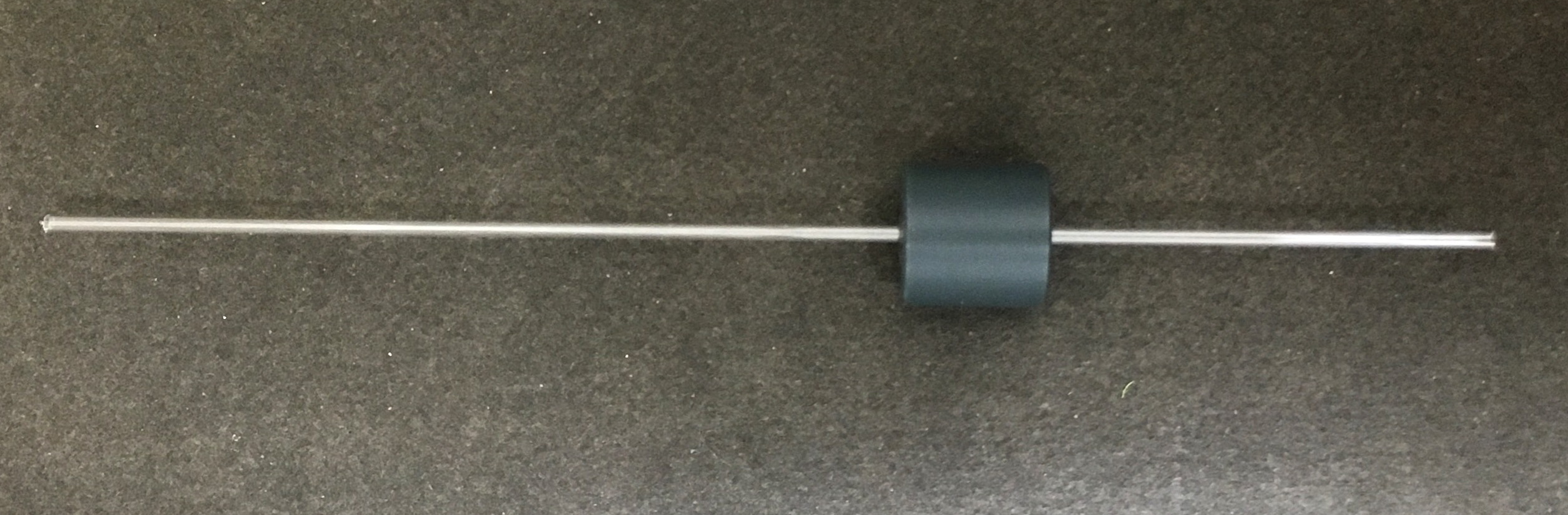
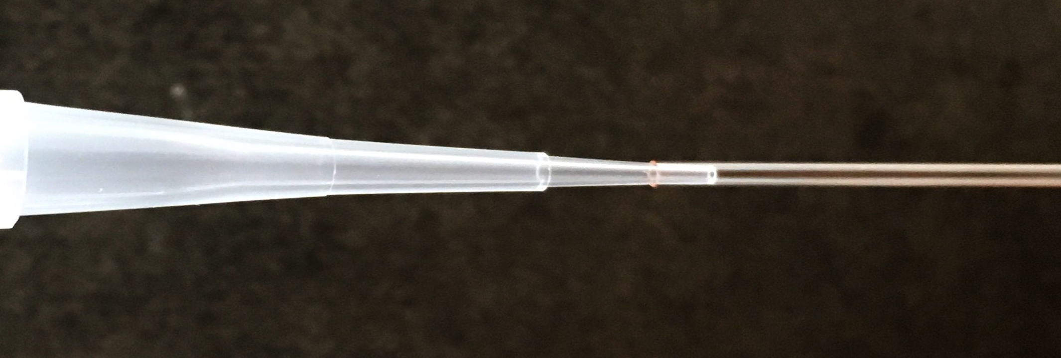
We used liquid 90Y, separated from 90Sr and purified at the 10-7 level by PerkinElmer Inc. for medical treatments. Prior to injection of 90Y a plastic holder was glued to the capillary, Figure 1(a). In order to safely insert the 90Y droplet, the capillary was placed into a plastic stand supported by the holder. A Gilson pipette was used to injected 2 L of 90Y source. We then wiped the capillary with a dry cotton pad and moved the droplet down with 8 L of air, injected from the pipette with a new end. The accuracy in this procedure is very important to avoid accidental breakage, as the diameter of a plastic end of the pipette is only slightly smaller than the inner diameter of the capillary, Figure 1(b). Inaccurate air pipetting can split the 90Y into small droplets and hence the source can’t be considered as a point source. After the droplet is placed at a satisfactory position, the edges of the capillary are sealed using a butane gas torch. The seals are visually inspected under magnification; a good seal is accurate and has no glass bubbles. It was next soaked in a water bath, that was then tested for contamination, using a Geiger counter. Next the clean capillary was placed into a vacuum canister air pump storage box. If the droplet either moves or splits into smaller droplets under vacuum, this indicates a poor seal and must be repeated
We prepared two calibration sources to perform the tests in the University of Sussex and in the University of Pennsylvania. The capillary with the source was shipped in a custom designed thick acrylic container, that protected it from damage.
3 Measurements at the University of Sussex
Initial tests were performed in the radiation laboratory at the University of Sussex. The experimental setup consists of two Hamamatsu 1” PMTs H10721-210 PMTs and a disk shaped vessel with diameter 6 cm filled with LAB PPO inside a dark box, and a Tektronix MSO2024 oscilloscope.
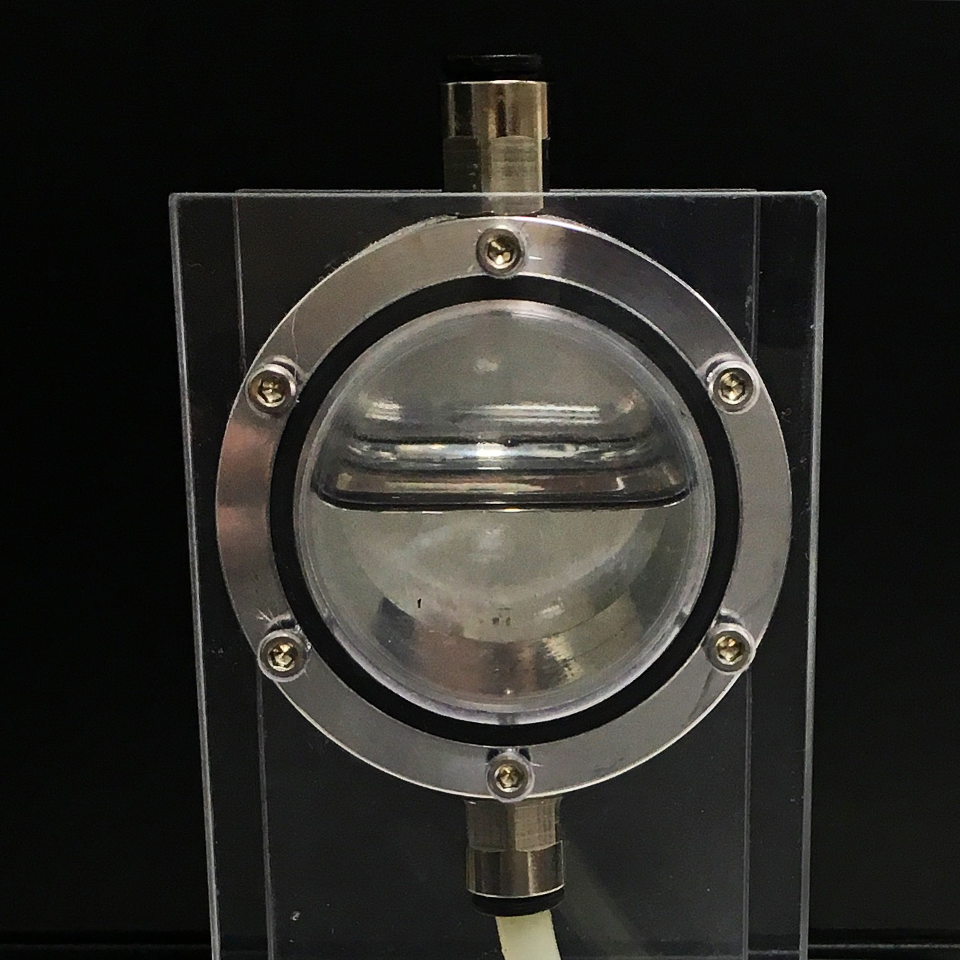
The capillary is placed inside the scintillator filled vessel, Figure 2. Due to the small volume of the vessel and high decay rate of the 90Y the contribution from cosmic ray muons is negligible. Signals were readout via the oscilloscope and analysed by custom written programs using LABVIEW and Python.
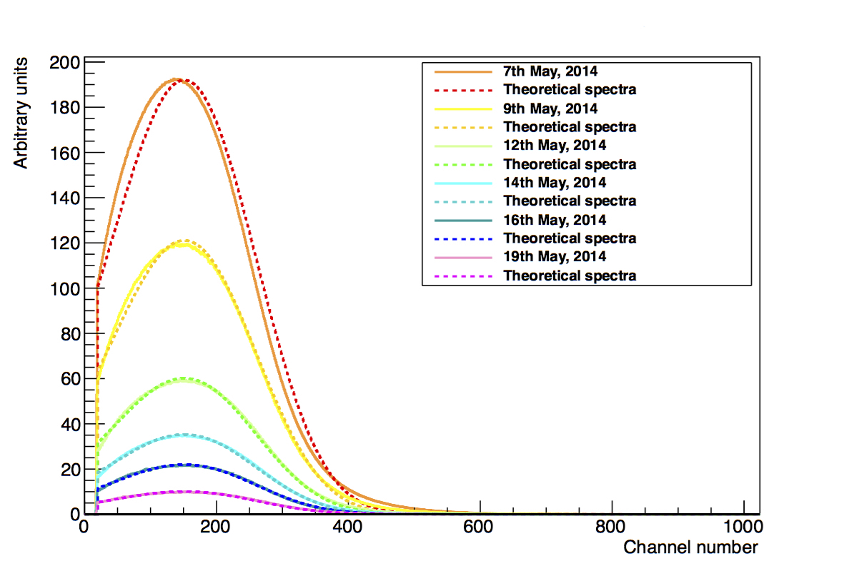
Data from several days agrees with the theoretically predicted spectrum of 90Y decay, Figure 3(a). During the first day of data taking, when the activity of the source was high, we observed pile up between multiple decays in the same readout window. The count rate over time also agrees with the expected half-life, Figure 3(b), confirming that we can observe 90Y decay betas from the source with minimal attenuation.
4 Measurements at the University of Pennsylvania
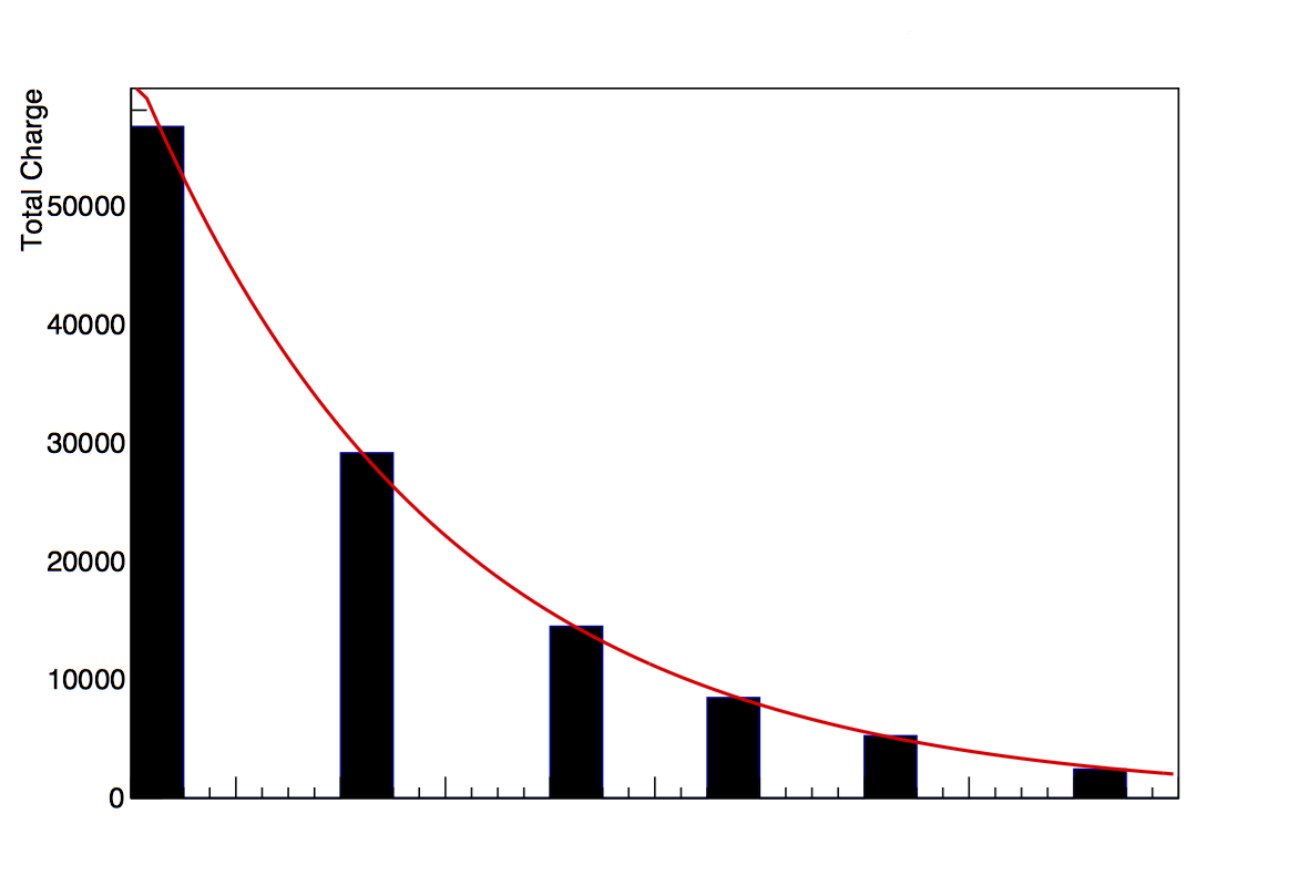
Using a large spherical acrylic vessel (diameter 40 cm) at the University of Pennsylvania we were able to make more precise measurements to study the scintillator cocktail properties. The source capillary was placed in the tank using a custom designed mount. Further data was collected with a 60Co test disk source attached to the spherical vessel from the outside to stop betas from entering the scintillator volume. The experimental setup includes five Hamamatsu PMTs: a ETL-9354KB PMT that was used as the trigger PMT, two R11780-HQE PMTs and two R1408 PMTs, that have been used in the SNO experiment. To accurately simulate the PMT response, the single photoelectron distribution was measured and then convolved with the simulated charge distribution from 90Y decay. The final modelled charge distribution was fit to the obtained data. Using the echidna software designed by the University of Sussex and Queen Mary University of London for fitting and limit setting tasks. The parameters of the fit, including a charge scale and an offset, have been applied to simulations of 60Co and compared to obtained data. Poor convergence in the fit indicated discrepancies in the scintillator model, triggering further study.
5 Conclusion and future directions
These studies have contributed to improve modelling of the scintillator response and validated this ex-situ source calibration technique. However these measurements were challenging, and due to the delicate nature of the capillary source, we conclude deployment of such a source within the SNO+ detector represents too high risk to detector contamination, despite the short source half-life. One possible approach is to contain the capillary within a secondary scintillator filled acrylic sphere for deployment into SNO+, but this study will be analysing this particular scintillator, rather than the scintillator volume of the detector.
ACKNOWLEDGEMENTS
This research was supported by ERC grant 278310 under the FP7 framework. We are grateful to the University of Sussex group for providing access to their radiation laboratory and the University of Pennsylvania group for helping to perform 90Y source measurements in various scintillator cocktails.
References
- [1] S. Andringa et al. [SNO+ Collaboration], Current Status and Future Prospects of the SNO+ Experiment, Adv. High Energy Phys. 2016, 6194250 doi:10.1155/2016/6194250 [arXiv:1508.05759 [ins-det]].
- [2] J.R. Wilson, Probing fundamental properties of the neutrino at the SNO+ Experiment, ERC Grant Proposal, Accepted in 2011, [ ].