Comparative Analysis of Initial Access Techniques
in 5G mmWave Cellular Networks
Abstract
The millimeter wave frequencies (roughly above GHz) offer the availability of massive bandwidth to greatly increase the capacity of fifth generation (5G) cellular wireless systems. However, to overcome the high isotropic pathloss at these frequencies, highly directional transmissions will be required at both the base station (BS) and the mobile user equipment (UE) to establish sufficient link budget in wide area networks. This reliance on directionality has important implications for control layer procedures. Initial access in particular can be significantly delayed due to the need for the BS and the UE to find the initial directions of transmission. This paper provides a survey of several recently proposed techniques. Detection probability and delay analysis is performed to compare various techniques including exhaustive and iterative search. We show that the optimal strategy depends on the target SNR regime.
Index Terms:
Wireless; 5G cellular; mmWave; Initial Access.I Introduction
The fifth generation of cellular systems (5G) is positioned to address the demands and business contexts of 2020 and beyond. In order to face the continuing growth in demand from subscribers for a better mobile broadband experience, there is a need to push the performance to provide, for example [1]: (i) much greater throughput, at least Gbps or more data rates, to support ultra-high definition video and virtual reality applications; (ii) much lower latency, less than ms, to support real time mobile control and Device-to-Device (D2D) applications and communications; (iii) ultra-high reliability and much higher connectivity; (iv) lower energy consumption, reduced by a factor of , to improve the battery life of connected devices.
In order to deal with these requirements, some key aspects have been identified to make this future network a reality. Since current micro-wave (W) spectrum under GHz is fragmented and crowded, there has been significant interest in the millimeter wave (mmWave) bands above 10 GHz, where a vast amount of largely unused spectrum is available. On one hand, the enormous amount of available spectrum can support the higher data rates required in future mobile broadband access networks. Moreover, the physical size of antennas at mmWave frequencies is so small that it becomes practical to build very large antenna arrays (e.g., elements) to provide further gains from spatial isolation and multiplexing. On the other hand, to overcome the high isotropic pathloss of the mmWave frequencies, outdoor cellular links will need highly directional transmissions. This complicates several control layer procedures, but is particularly challenging for initial access (IA). Initial access is the procedure by which a mobile user equipment (UE) establishes a physical link connection with a base station (BS). In current LTE systems, IA can be performed on omni-directional channels. Beamforming or other directional transmissions can be performed after a physical link is established. However, in the mmWave range, the IA procedure must provide a mechanism by which the BS and UE can determine suitable initial directions of transmission. This directional search can significantly delay the cell search and access procedure.
This paper provides a survey of recent directional IA techniques for mmWave cellular systems. We compare various search schemes, including exhaustive search and an iterative scheme that successively narrows the search direction. We study the performance in terms of misdetection probability and discovery delay, under some overhead constraints and as a function of the channel conditions. Our results show that the optimal strategy depends on the target SNR regime and provide some guidance about the best scheme to use, according to the scenario.
The paper is organized as follows. In Section II, we review some of the most important contributions related to IA, while in Section III we describe in detail the two initial access procedures we are going to compare. In Section IV we evaluate through simulations some comparison metrics, such as misdetection probability and discovery delay, and finally, in Section V, we summarize our major findings.
II Related work
Papers on IA are very recent, since research in this field is just at the dawn. Most literature refers to challenges that have been analyzed in the past at lower frequencies in ad hoc wireless network scenarios or, more recently, referred to the 60 GHz IEEE 802.11ad WLAN and WPAN scenarios.
The initial access problem in mmWave cellular networks has been considered, for example, in [2], where the authors proposed an exhaustive method to sequentially scan the angular space. In [3], a directional cell discovery procedure is proposed, where base stations periodically transmit synchronization signals, potentially in time-varying random directions, to scan the angular space. Also in [4] initial access design options are compared, considering different scanning and signaling procedures, to evaluate access delay and system overhead; the analysis demonstrates significant benefits of low-resolution fully digital architectures in comparison to single stream analog beamforming. In [5], random directional beamforming is considered for mmWave multi-user MISO downlink systems. By using asymptotic techniques, the performance of the algorithm is analyzed, based on a uniform random line-of-sight channel model suitable for highly directional mmWave radio propagation channels.
Paper [6] analyzes some low-complexity beamforming approaches for initial UE discovery in MIMO systems, showing that users with a reasonable link margin can be quickly discovered by the proposed design with a smooth roll-off in performance as the link margin deteriorates.
Again [7] presents a two-phase hierarchical procedure, while [8] describes an energy-efficient link configuration mechanism, by determining the optimal number of beams in a proposed two-stage beam training algorithm. In [9], in order to alleviate the exhaustive search delay issue, two types of adaptive beam training protocols are proposed. For fixed modulation, the proposed protocol allows for interactive beam training, stopping the search when a local maximum of the power angular spectrum is found that is sufficient to support the chosen modulation/coding scheme (approaches to prioritize certain directions determined from the propagation geometry, long-term statistics, etc. are also presented). For adaptive modulation, the proposed protocol uses iterative multi-level beam training concepts for fast link configuration that provide an exhaustive search with significantly lower complexity. In [10], a beamforming and cell search method is proposed for a mobile station with an antenna array to compensate the high attenuation in a mmWave OFDM-based cellular system.
Also in [11], exploiting a certain sparsity of mmWave channels, a low-complexity beam selection method for beamforming by low-cost analog beamformers is derived. It is shown that beam selection can be carried out without explicit channel estimation, using the notion of compressive sensing.
With respect to this prior literature, our goal is to compare multiple IA procedures, in order to determine which is the preferred one, in terms of coverage probability and delay, to be implemented when considering a realistic dense, urban, multi-path scenario.
III Initial Access in 5G-mmWave networks
We assume a slot structure similar to the one described in [4]. Then, we assume that the PSS is transmitted periodically once every seconds for a duration of seconds, in each transmission. In this work, we will consider potentially different signal periods. A detailed description of each parameter that we will use in our simulation can be found in Section IV. In this work, we consider two schemes, inspired by similar ideas in [2] and [7], with some modifications of the transmitting and receiving scheme, as explained below.
III-A Exhaustive search
Exhaustive search performs a brute-force sequential beam searching: the BS has a predefined codebook of directions (each identified by a BF vector) that covers the whole angular space.
The goal is to identify the best TX-RX beam pair for each BS to connect with each UE. Therefore, the BS sends messages in those directions, in different slots, through narrow beams, while the UE configures its antenna array in order to directionally receive said messages. Upon the reception of a PSS, the user evaluates the SNR and, if it is above a fixed threshold, feeds it back to the BS through a message. After having scanned the whole angular space, the BS determines the best beam to directionally reach the UE, on the basis of the highest received SNR (which corresponds to a certain direction).
As a design choice, the BS is equipped with antennas and can steer beams in directions, exploiting its maximum achievable BF gain. The UE has a set of combining vectors that also cover the whole angular space. In order to compare two different techniques, the UE can receive PSSs through wide beams (using a antenna pattern) or through narrower beams (using all the antenna elements it is equipped with).
| Step 1 - DL: BS transmits a PSS in sector /16, UE receives in sector . |
![[Uncaptioned image]](/html/1605.00101/assets/x1.png)
|
||
|---|---|---|---|
| Step 2 - DL: BS transmits a PSS in sector /16, UE receives in sector . |
![[Uncaptioned image]](/html/1605.00101/assets/x2.png)
|
||
| Step 3 - DL: BS transmits a PSS in sector /16, UE receives in sector . |
![[Uncaptioned image]](/html/1605.00101/assets/x3.png)
|
||
| Step 4 - DL: BS transmits a PSS in sector /16, UE receives in sector . |
![[Uncaptioned image]](/html/1605.00101/assets/x4.png)
|
||
|
|||
| Step 6 - UL: BS receives in the same sector /16, UE transmits in its best sector (say ). UE transmits the information on its maximum perceived SNR, together with its RNTI. BS collects such information into a BS table. From now on, it knows that this user can be reached through sector /16 with this SNR. |
![[Uncaptioned image]](/html/1605.00101/assets/x5.png)
|
Let us consider a 4-direction reception (the 8-direction case is its natural extension). At the BS side, PSS messages are sent in the same direction, in consecutive DL slots, in order to match with one of the reception beams at the UE side. Then, in the UL slot, the user feeds back its , which is in turn collected at the BS side (in receiving mode). These DL and UL slots constitute an IA macroelement. In Table I, as an example, we just consider the macroelement , referred to the BS steering direction . However, the same steps will be hierarchically repeated for each one the macroelements that the BS will send.
After the UL slot in Step , the UE returns to the reception mode, restarting the directional scan, looking for new PSSs. On the other hand, the BS configures its antenna elements in order to steer another macroelement block in the next direction (Step 1 is cyclically performed again), until the whole space is covered.
When all the directions have been scanned by the BS, both UE and BS select the best beam to reach each other, and start using it. In particular, the BS checks its BS table and finds, among the saved entries, the sector corresponding to the highest received SNR. This beam will be chosen to reach the UE.
III-B Iterative search
Iterative search performs a two-stage scanning of the angular space. Again, a codebook is available, in order to send synchronization messages in deterministic directions. In the first phase, the BS performs an exhaustive search through macro wide beams and, after having scanned the whole space, determines its best beam, on the basis of the highest received SNR (similarly the UE finds the best direction to reach the BS). In the second phase, the BS refines its search only in the previously identified wide beams.
In the first phase, the BS will send PSS messages in macro directions through wide beams, using antennas. In the second phase, instead, the BS will send the refining PSSs through narrow beams, through antennas. At the UE side, the user can receive PSSs through or beams, while in the second phase the UE will configure its antenna array to receive only in its best direction (previously identified).
Let us consider a -direction reception (the -direction case is its natural extension). Similar to the exhaustive procedure, in the first phase, an IA macroelement is constituted of four DL slots (for the four PSSs sent in the same direction, to match with one UE receiving beam) and one UL slot, reserved for the PSSRX. Four macroelements are sent in the four directions, to cover the whole angular space. At the end, the BS determines the best macro direction to be refined, while the UE selects its best receiving beam. In the second phase, the BS steers narrow beams to refine sector : just one PSS per beam is sent, because now the UE no longer needs to scan in reception (in fact it will receive only through its best direction, determined during the first phase).
Dwelling on the case where UE receives in directions, in Table II we report the steps to be performed in the iterative first phase, when considering, for example, macroelement .
| Steps 1 to 4 - DL: BS transmits a PSS in sector /4, UE receives, in consecutive slots, in sectors to , to cover the whole angular space. |
![[Uncaptioned image]](/html/1605.00101/assets/x6.png)
|
||
|---|---|---|---|
|
|||
| Step 6 - UL: BS receives in the same sector /4, UE transmits in its best sector (say ). UE transmits the information on its maximum perceived SNR, together with its RNTI. BS collects such information into a BS table. |
![[Uncaptioned image]](/html/1605.00101/assets/x7.png)
|
When all the macro directions have been scanned, UE selects its best receiving beam, to reach the BS, while the BS selects the best macro sector that will be refined in the second phase, whose iterative steps are shown in Table III.
| Step 1 - DL: BS transmits one single refining PSS in small sector /4, UE receives just through its best sector (in this case sector ) that has been previously identified in the first phase, without scanning the angular space. |
![[Uncaptioned image]](/html/1605.00101/assets/x8.png)
|
|
| Step 2 - UL: BS receives in the same sector /4, UE transmits in its best sector the information on its maximum perceived SNR, together with its RNTI. BS collects again such info into its BS table. |
![[Uncaptioned image]](/html/1605.00101/assets/x9.png)
|
After the UL slot, UE returns in reception mode and BS inspects the next refining direction, until the whole macro sector is scanned. Finally, the BS checks again its table and finds the sector (now a narrow beam) corresponding to the highest SNR saved. At this time, both BS and UE know how to directionally reach each other, in the best possible way.
IV Simulation model and numerical results
In the simulations, we will assume a static deployment, where no users are moving, so that no handover management or UE motion tracking is required. The parameters are based on realistic system design considerations and are summarized in Table IV.
The channel model we have implemented is based on recent real-world measurements at GHz in New York City to provide a realistic assessment of mmWave micro and picocellular networks in a dense urban deployment. Statistical models are derived for key channel parameters including: (i) a distance-based pathloss, which models line-of-sight (LOS), non-line-of-sight (NLOS) and outage conditions; (ii) spatial clusters, described by central azimuth and elevation angles, fractions of power and angular beamspreads, (iii) a small-scale fading model, where each of the path clusters is synthesized with a large number of subpaths, each one having its own peculiarities on horizontal and vertical angles (generated around the cluster central angles). Further details of the channel model and its parameters can be found in [12].
A typical 5G cell is envisioned to have a radius of around m, according to the channel characteristics. However, we will see that, referring to the channel described in [12], much smaller cell radii should be considered, in order to provide good performance to most users.
In this work, we just refer to analog beamforming, that is implemented through Uniform Planar Array (UPA). A set of two dimensional antenna arrays is used at both BS and UE. The array can be comprised of , or elements. The spacing of the elements is set to , where is the wavelength. These antenna patterns were chosen following the results in [3] and can be shown to offer excellent system capacity for small cell urban deployment, together with easy packageability (for instance, at GHz, a array will have a size of roughly cm cm).
Referring to the IA procedures, we will consider an SNR thresholds dB. If the SNR is below , it is assumed that the UE does not receive any PSS signal. Reduction of permits to find more users, at the cost of designing more complex (and expensive) receiving schemes, able to detect more corrupted messages. Each signal has a minimum duration s, that is sufficiently small for the channel to be coherent even at the very high frequencies used for mmWave communication [4]. Moreover, beam switching time from one sector to another takes around ns, which is much less than s and so can be neglected [13]. Simulations are conducted increasing the distance of the UE from the BS, placed at coordinates m, in m increments. At each iteration, the user is deployed within an annulus having outer radius and inner radius , with , according to a uniform distribution. In order to make reliable measurements through a Montecarlo estimation, each simulation is independently repeated times.
| Parameter | Value | Description |
|---|---|---|
| BW | GHz | Total system bandwidth |
| DL - UL | dBm | Transmission power |
| NF | dB | Noise figure |
| GHz | Carrier frequency | |
| or m | Cell radius | |
| dB | SNR threshold | |
| BS antenna | ||
| UE antenna | or | |
| BS position | m | |
| UE position | varied | Uniform in annulus |
| UE speed | m/s | No mobility |
| BF | analog | Beamforming architecture |
| min. | min. signal duration | |
| Overhead | ||
| varied according to | Period between transmissions | |
| Propagation loss model | LOS, NLOS, outage | According to [12] |
In our study, we evaluate the performance in terms of discovery delay and misdetection probability. Discovery delay is the time a BS needs to identify all users in its coverage range, and can be computed as explained in subsection IV-A. The misdetection probability (PMD) is the probability that a UE within the cell is not detected by the BS, perceiving SNR below threshold. By making a large number of independent experiments, we keep a record of the number of times the UE’s perceived SNR is below the threshold, to determine the corresponding PMD statistics. We will consider different antenna array configurations, according to the reception mode the UE is programmed to use (either 4 or 8 receiving beams).
IV-A Required number of slots
First of all, we compare the different IA techniques from the discovery delay point of view. Considering a signal duration s and a target overhead of , the time between two consecutive slot transmissions must be at least s. Given that an IA procedure requires slots to be sent, the delay in Table V can be computed as .
| Procedure | TX antennas | RX antennas | Delay | |||
|---|---|---|---|---|---|---|
| Exh. | ms | |||||
| Exh. | ms | |||||
| It. |
|
ms | ||||
| It. |
|
ms |
We clearly see that iterative techniques outperform the exhaustive ones in terms of discovery delay. In fact, there is no need to scan the whole angular space to find the UE, since it is sufficient to just refine a macro sector.
IV-B Misdetection probability
Figure 1 plots the misdetection probability of both exhaustive and iterative IA techniques, when UE receives in either or directions, varying the distance between BS and UE, from to meters. Threshold is dB.
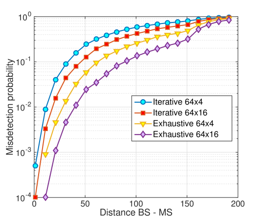
The lower the number of antennas at both UE and BS (scanning through fewer directions in reception or transmitting through wider beams), the lower the BF gain, the lower the SNR perceived by the UE and the higher the probability that this SNR is below the threshold. For this reason, since iterative search makes use of a small antenna array in the first phase (just elements), it presents a higher misdetection probability, at the same distance, with respect to exhaustive searches. However, in the range meters, almost all algorithms present acceptable misdetection probability levels. At these distances, LOS condition is very likely met, and pathloss and PMD are sufficiently small even when exploiting iterative searches. Therefore, when considering cells having very small radius, it may not be desirable to implement exhaustive procedures, which are affected by higher discovery delays. In the range meters, almost all algorithms present instead unacceptable misdetection probability values, showing that better IA procedures need to be designed for cells of this size to be able to correctly operate.
Finally, we highlight the change of slope in the line, of Figure 1, around m. In fact, at this distance, the outage pathloss condition is very likely to occur, with a consequent considerable reduction of perceived SNR even for exhaustive scenarios where high BF is achieved, which explains the sudden increase of PMD.
IV-C Trade-off between delay and PMD (total delay)
Considering now a worst-case scenario, we want to constrain the misdetection probability to be below a certain threshold (i.e., ) for most users in the cell. If the cell radius is around m, we want that PMD even for edge users, at meters from the BS. In order to decrease the PMD, we can increase the signal duration: if is increased, the BS transmits its PSS for a longer time in the same sector, so that UEs belonging to that sector can accumulate a higher amount of energy. This results in an increased SNR and in a reduced PMD. Increasing the signal duration is simulated by correspondingly lowering . In such a way, if the signal duration is doubled, the SNR also doubles and this is equal to reducing by dB. From the results in Figure 2, we can compute the minimum signal length to meet the PMD requirements for edge users.
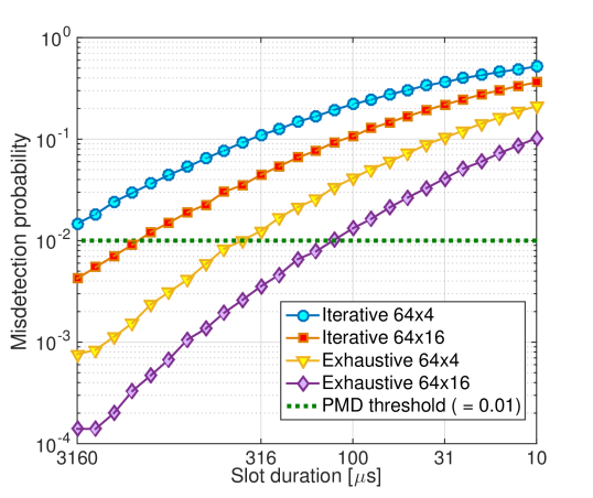
In Table VI, we compute the total delay that takes care of both the required number of slots to perform each IA technique and the PMD specifications. According to the specific value of that has been found, the corresponding value of should be chosen, to maintain a constant overhead of .
| Procedure | min. | Total delay | ||
|---|---|---|---|---|
|
s | ms | ||
|
s | ms | ||
|
s | ms | ||
|
s | ms |
We can see that iterative techniques require very long signals, to overcome the low BF gain and collect enough energy to perceive a sufficiently high SNR. On the other hand, exhaustive searches can have shorter slots.
At least for this kind of scenarios, where the cell size is around m, the total delay of iterative searches is higher than that of the exhaustive scheme, which seems therefore to be preferable (if we want to guarantee good coverage probability even for edge users). Otherwise, if we want to grant a good PMD just for closer users, iterative techniques will lead to a sufficiently high SNR even exploiting shorter slots.
Moreover, we highlight that the iterative technique is not recommended when dealing with very dense networks. When a UE is detected in a certain macro direction, after the first phase, this sector is consequently refined. If multiple users are found in different macro directions, it is necessary to refine all of them, one at a time. This way, discovery can take longer than with exhaustive techniques, and even with a worse misdetection probability, due to low first phase BF gain. It is advisable to implement such an iterative procedure only when the users’ arrival rate is low and when the probability that multiple UEs are under the coverage area of different macro sectors is negligible.
V Conclusions and future works
In this work, we have studied, analyzed and compared possible implementations of initial access techniques for upcoming 5G millimeter-wave cellular networks. The main idea is that, in order to overcome the bad mmWave channel propagation conditions, directionality should be realized also in the initial synchronization-access phase. Our analysis has indeed demonstrated the following key findings:
-
•
There exists a trade-off between IA delay and misdetection probability: on the one hand, iterative techniques require fewer slots to perform the angular search, with respect to exhaustive algorithms; on the other hand, they make use of a small antenna array in the first phase and present higher misdetection probability levels.
-
•
When wanting to grant a minimum coverage level also to edge users (say around meters from the BS) and when considering a dense, urban, multipath mmWave channel, exhaustive procedures are preferred, since they achieve a smaller total delay, in comparison to other IA techniques.
As part of our future work, digital (or hybrid) beamforming architectures will be studied to steer multiple narrow beams in multiple directions at the same time, in order to reconcile the low discovery delay goal with low misdetection probability. Furthermore, IA procedures where HetNets and Context-Information are exploited deserve a deeper investigation.
Acknowledgement
Part of this work has been performed in the framework of the H2020 project METIS-II co-funded by the EU. The authors would like to acknowledge the contributions of their colleagues from METIS-II although the views expressed are those of the authors and do not necessarily represent the views of the METIS-II project.
References
- [1] Nokia, “Looking ahead to 5G,” May 2014, White Paper. [Online]. Available at http://networks.nokia.com/file/28771/5g-white-paper.
- [2] C. Jeong, J. Park, and H. Yu, “Random access in millimeter-wave beamforming cellular networks: issues and approaches,” Communications Magazine, IEEE, vol. 53, no. 1, pp. 180–185, January 2015.
- [3] C. Barati, S. Hosseini, S. Rangan, P. Liu, T. Korakis, S. Panwar, and T. Rappaport, “Directional cell discovery in millimeter wave cellular networks,” Wireless Communications, IEEE Transactions on, vol. 14, no. 12, pp. 6664–6678, Dec 2015.
- [4] C. N. Barati, S. A. Hosseini, M. Mezzavilla, S. Rangan, T. Korakis, S. S. Panwar, and M. Zorzi, “Directional initial access for millimeter wave cellular systems,” CoRR, vol. abs/1511.06483, 2015. [Online]. Available: http://arxiv.org/abs/1511.06483
- [5] G. Lee, Y. Sung, and J. Seo, “Randomly-directional beamforming in millimeter-wave multi-user miso downlink,” Wireless Communications, IEEE Transactions on, vol. PP, no. 99, pp. 1–1, 2015.
- [6] V. Raghavan, J. Cezanne, S. Subramanian, A. Sampath, and O. Koymen, “Beamforming tradeoffs for initial UE discovery in millimeter-wave MIMO systems,” Selected Topics in Signal Processing, IEEE Journal of, vol. PP, no. 99, pp. 1–1, 2016.
- [7] V. Desai, L. Krzymien, P. Sartori, W. Xiao, A. Soong, and A. Alkhateeb, “Initial beamforming for mmwave communications,” in Signals, Systems and Computers, 2014 48th Asilomar Conference on, Nov 2014, pp. 1926–1930.
- [8] J. Kim and S.-N. Hong, “Dynamic two-stage beam training for energy-efficient millimeter-wave 5G cellular systems,” Telecommunication Systems, vol. 59, no. 1, pp. 111–122, 2014. [Online]. Available: http://link.springer.com/10.1007/s11235-014-9891-6
- [9] J. Kim and A. Molisch, “Fast millimeter-wave beam training with receive beamforming,” Communications and Networks, Journal of, vol. 16, no. 5, pp. 512–522, Oct 2014.
- [10] R. Pec, K. S. Kim, I. S. Kim, B. W. Ku, and Y. S. Cho, “Cell searching and DoA estimation for a mobile station with antenna array in mm-wave cellular communications,” in Vehicular Technology Conference (VTC Spring), 2014 IEEE 79th, May 2014, pp. 1–5.
- [11] J. Choi, “Beam selection in mm-Wave multiuser MIMO systems using compressive sensing,” Communications, IEEE Transactions on, vol. 63, no. 8, pp. 2936–2947, Aug 2015.
- [12] M. Akdeniz, Y. Liu, M. Samimi, S. Sun, S. Rangan, T. Rappaport, and E. Erkip, “Millimeter wave channel modeling and cellular capacity evaluation,” Selected Areas in Communications, IEEE Journal on, vol. 32, no. 6, pp. 1164–1179, June 2014.
- [13] K. Chandra, R. Prasad, I. Niemegeers, and A. Biswas, “Adaptive beamwidth selection for contention based access periods in millimeter wave wlans,” in Consumer Communications and Networking Conference (CCNC), 2014 IEEE 11th, Jan 2014, pp. 458–464.