Optimization of multilayered nanotubes for maximal scattering cancellation
Carlos Díaz-Aviñó, Mahin Naserpour, and Carlos J. Zapata-Rodríguez∗
Department of Optics and Optometry and Vision Science, University of Valencia,
Dr. Moliner 50, Burjassot 46100, Spain
∗carlos.zapata@uv.es
Abstract
An optimization for multilayered nanotubes that minimizes the scattering efficiency for a given polarization is derived. The cylindrical nanocavities have a radially periodic distribution, and the marginal layers that play a crucial role particularly in the presence of nonlocalities are disposed to reduce the scattering efficiency up to two orders of magnitude in comparison with previous proposals. The predominant causes leading to such invisibility effect are critically discussed. A transfer-matrix formalism is additionally developed for the fast estimation of the scattering efficiency of the nanostructures.
OCIS codes: (290.5839) Scattering, invisibility; (240.6680) Surface plasmons; (260.2065) Effective medium theory.
References and links
- [1] U. Leonhardt, “Optical conformal mapping,” Science 312, 1777–1780 (2006).
- [2] J. B. Pendry, D. Schurig, and D. R. Smith, “Controlling electromagnetic fields,” Science 312, 1780–1782 (2006).
- [3] W. Cai, U. K. Chettiar, A. V. Kildishev, and V. M. Shalaev, “Optical cloaking with metamaterials,” Nat. Photon. 1, 224–227 (2007).
- [4] A. Alu and N. Engheta, “Achieving transparency with plasmonic and metamaterial coatings,” Phys. Rev. E 72, 016623 (2005).
- [5] B. Edwards, A. Alu, M. G. Silveirinha, and N. Engheta, “Experimental verification of plasmonic cloaking at microwave frequencies with metamaterials,” Phys. Rev. Lett. 103, 153901 (2009).
- [6] S. Tricarico, F. Bilotti, and L. Vegni, “Scattering cancellation by metamaterial cylindrical multilayers,” J. Eur. Opt. Soc, Rapid Publ. 4, 09021 (2009).
- [7] D. S. Filonov, A. P. Slobozhanyuk, P. A. Belov, and Y. S. Kivshar, “Double-shell metamaterial coatings for plasmonic cloaking,” Phys. Status Solidi RRL 6, 46–48 (2012).
- [8] K.-H. Kim, Y.-S. No, S. Chang, J.-H. Choi, and H.-G. Park, “Invisible hyperbolic metamaterial nanotube at visible frequency,” Sci. Rep. 5, 16027 (2015).
- [9] T. J. Arruda, A. S. Martinez, and F. A. Pinheiro, “Tunable multiple Fano resonances in magnetic single-layered core-shell particles,” Phys. Rev. A 92, 023835 (2015).
- [10] M. V. Rybin, D. S. Filonov, P. A. Belov, Y. S. Kivshar, and M. F. Limonov, “Switching from visibility to invisibility via Fano resonances: Theory and experiment,” Sci. Rep. 5, 8774 (2015).
- [11] L. Ferrari, C. Wu, D. Lepage, X. Zhang, and Z. Liu, “Hyperbolic metamaterials and their applications,” Prog. Quant. Electron. 40, 1–40 (2015).
- [12] C. Díaz-Aviñó, M. Naserpour, and C. J. Zapata-Rodríguez, “Edge effects on invisibility of hyperbolic multilayered nanotubes,” arXiv:1603.08317 (2016).
- [13] C. F. Bohren and D. R. Huffman, Absorption and scattering of light by small particles (Wiley, 1998).
- [14] P. Yeh, A. Yariv, and C.-S. Hong, “Electromagnetic propagation in periodic stratified media. l. general theory,” J. Opt. Soc. Am. 67, 423–438 (1977).
- [15] H. E. Bussey and J. H. Richmond, “Scattering by a lossy dielectric circular cylindrical multilayer, numerical values,” IEEE Trans. Antennas Propag. 23, 723–725 (1975).
- [16] G. A. Shah, “Scattering of plane electromagnetic waves by infinite concentric circular cylinders at oblique incidence,” Mon. Not. R. Astron. Soc. 148, 93–102 (1970).
- [17] C. A. Balanis, Advanced engineering electromagnetics (Wiley, New York, 1989).
- [18] E. Shamonina, V. A. Kalinin, K. H. Ringhofer, and L. Solymar, “Imaging, compression and Poynting vector streamlines with negative permittivity materials,” Electron. Lett. 37, 1243–1244 (2001).
- [19] S. Feng, M. Elson, and P. Overfelt, “Transparent photonic band in metallodielectric nanostructures,” Phys. Rev. B 72, 085117 (2005).
- [20] C. J. Zapata-Rodríguez, D. Pastor, M. T. Caballero, and J. J. Miret, “Diffraction-managed superlensing using plasmonic lattices,” Opt. Commun. 285, 3358–3362 (2012).
- [21] D. Torrent and J. Sánchez-Dehesa, “Radial wave crystals: Radially periodic structures from anisotropic metamaterials for engineering acoustic or electromagnetic waves,” Phys. Rev. Lett. 103, 064301 (2009).
- [22] H. Kettunen, H. Wallén, and A. Sihvola, “Tailoring effective media by Mie resonances of radially-anisotropic cylinders,” Photonics 2, 509–526 (2015).
- [23] P. Yeh, Optical waves in layered media (Wiley, New York, 1988).
- [24] S. A. Ramakrishna, J. B. Pendry, M. C. K. Wiltshire, and W. J. Stewart, “Imaging the near field,” J. Mod. Opt. 50, 1419–1430 (2003).
- [25] D. E. Aspnes, “Plasmonics and effective medium theory,” in “Ellipsometry at the Nanoscale,” , M. Losurdo and K. Hingerl, eds. (Springer, Berlin, 2013), pp. 203–224.
- [26] C. Díaz-Aviñó, M. Naserpour, and C. J. Zapata-Rodríguez, “Tunable scattering cancellation of light using anisotropic cylindrical cavities,” arXiv:1604.03875 (2016).
- [27] J. Elser, V. A. Podolskiy, I. Salakhutdinov, and I. Avrutsky, “Nonlocal effects in effective-medium response of nanolayered metamaterials,” Appl. Phys. Lett. 90, 191109 (2007).
- [28] J. Wang, T. Zhan, G. Huang, P. K. Chu, and Y. Mei, “Optical microcavities with tubular geometry: properties and applications,” Laser Photonics Rev. 8, 521–547 (2014).
1 Introduction
The rapid theoretical and experimental advancement in nanomaterials during the last two decades has enabled to engineer multifunctional devices for the control of light with unprecedented proficiency. For instance, some schemes which are mostly based on transformation optics allow the isolation of a region from interaction with an external light that, in addition, remains unperturbed far from the shadowed space [1, 2, 3]. Consequently, an outside observer cannot detect any target placed inside the cloak by means of an electromagnetic wave field. However, such cloaking devices are commonly subject to stringent conditions like the need of materials with exotic electromagnetic parameters reducing their applicability to specific frequencies. Alternatively we may turn a nanoparticle to be invisible by integrating some nanostructured element like ultrathin coatings and metasurfaces in such a way that scattering of the arrangement is much reduced in comparison with the bare object [4, 5, 6, 7, 8]. In this case, light indeed interacts with the nanocomposite, but scattering from different elements interferes destructively to almost cancel the total scattered signal.
The origin of such scattering drop, thus reducing dramatically the overall visibility of the scatterer, may be attributed to different aspects of the light-matter interaction. For instance, the local polarizability of distinct components of a moderately sized object with opposite signs may be canceled out in a proper designed configuration [4, 5, 6]. The polarization vector in the elementary materials is anti-parallel with respect to each other, implying that a dipole moment of opposite phase is induced. Another approach for the cancellation of scattering from an engineered scatterer is based on the properties of the characteristic lineshape of the Fano resonance, where the emission of electromagnetic waves by the object create the interference between the nonresonant scattering from the particle and scattering by narrow Mie modes [9]. This effect has also been observed in high-index nanoparticles without additional coating layers [10]. Of particular interest follows the inclusion of epsilon-near-zero shells in the spectral range of interest, which may lead to a significant drop of the scattering spectrum and, in addition, create a shielding effect in the bounded space [7]. For scatterers with cylindrical symmetry (along the axis) and composed of dielectric and plasmonic materials, the effect of opposite polarizabilities is mostly observed in TMz-polarized wave fields, whereas Fano resonances may be simply utilized in TEz polarization configurations.
Recently, a multilayered metallodielectric nanotube with radially-periodic structure has been proposed, which presents a tunable spectral band with significant reduction of its scattering efficiency [8]. Such scattering cancellation is produced simultaneously for both polarizations and occurs when one of the components of the permittivity tensor characterizing the effective anisotropy of the metamaterial approaches zero, that is near the boundary of the hyperbolic regime [11]. Particularly for TEz-polarized fields, a large birefringence of the nanoshell enables a self-guiding effect along the radial direction that is applied to validate the observed scattering reduction.
In this work we extend the previous idea of employing radially-periodic metal-dielectric nanotubes to optimize the scattering cancellation of the nanocavity. For that purpose, we introduce a new degree of freedom that concerns the marginal layers set by the side of the core and the environment medium, the latter playing a critical role primarily in the presence of metamaterial nonlocalities [12]. We also present a critical discussion on the predominant causes leading to such invisibility effect. The estimation of our results is performed using the full-wave Lorenz-Mie method [13], and a matrix formulation is developed in order to further simplify the evaluation of the scattering efficiency, which presents some similarities to the transfer matrix formalism previously implemented in stratified plane metamaterials [14]. In fact, the later formulation might be applied to any complex multilayered cylindrical scatterer composed of homogeneous and isotropic materials.
2 The transfer matrix formulation
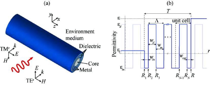
Let us consider a cylindrical shell formed by a multilayered metal-dielectric nanostructure, as illustrated in Fig. 1. The nanotube, which has a radius (), is composed of layers with a shell thickness given by . The relative permittivities of the metal and the dielectric determine the permittivity distribution of the metamaterial along the radial direction, . In this study we consider a periodic distribution, within the nanotube, where the period includes the width of the metal and the width of the dielectric. In particular, the permittivity is complex valued, thus taking into account losses in the metal. Here we examined nanotubes with a core material of permittivity and immersed in an environment medium of dielectric constant .
To estimate analytically the scattering efficiency of the multilayered nanocavity, we followed the Lorenz-Mie scattering method given in detail for instance in Refs. [15] and [16]. Following previously well-established algebraic treatments of plane multilayered photonic structures [14], here we propose a transfer-matrix formalism enabling a fast evaluation of the scattering (and potentially extinction) cross section of an infinitely-long cylindrical scatterer composed of a large number of layers.
In this section we assume that the nanotube is illuminated by a TMz plane wave propagating along the axis, as illustrated in Fig. 1. Let us point out that the case of TEz incident wave fields might be simply determined by means of the duality principle [17]. The electric field of the incident plane wave may be set as
| (1) |
where and are the radial and azimuthal cylindrical coordinates, respectively, is a constant amplitude, is the Bessel function of the first kind and order , and is the wavenumber in the vacuum. In Eq. (1) we used the Jacobi-Anger expansion of a plane wave in a series of cylindrical waves. The scattered electric field in the environment medium, , may be set as [13]
| (2) |
where is the Hankel function of the first kind and order , and the coefficients must be determined. The total electric field in the environment medium is simply . In a given layer of the nanostructured shell (medium ), , where , the electric field may be expressed analytically as [13]
| (3) |
where the wavenumber for a dielectric layer, and for a metallic layer. Finally, the electric field in the core of the multilayered tube () is expressed as
| (4) |
where the wavenumber .
The Lorenz-Mie scattering coefficients , , , and , are determined by means of the proper boundary conditions, that is, continuity of (the -component of) the electric field and the -component of the magnetic field, , established at the environment-multilayered medium interface given at and at internal interfaces set at (boundary with the core) and (). In particular, the boundary conditions applied at may be set in matrix form as
| (5) |
where the dynamical matrix
| (6) |
is given in terms of the reduced impedance () for the metallic (dielectric) layer, and for the core, . Here the prime appearing in and denotes derivative with respect to the variable . Note that is a real-valued matrix provided that the permittivity of the medium is also real. By applying the boundary conditions at we may write
| (7) |
where, in this case, we set and .
Importantly, we may estimate the fields in the core space and outside the nanotube without calculating the fields in the anisotropic medium by means of the following matrix equation:
| (8) |
where the matrix
By using this transfer matrix formalism, it is possible to evaluate analytically the scattering coefficient
| (12) |
which provide the estimation of the scattering efficiency as [13]
| (13) |
The invisibility condition is established provided that the scattering coefficients (or alternatively ) arrive simultaneously to a value near zero.
3 Optimization procedure
In this study we propose a multilayered metal-dielectric nanotube following a periodic distribution along the radial coordinate. The basic arrangement consisting of alternating metallic and dielectric layers of widths and , respectively, was recently introduced by Kim et al in Ref. [8]. As a new degree of freedom, we utilize a unit cell within which one of the layers may be surrounded by a second material, and consequently its associated layer must be split into two as illustrated in Fig. 1(b). Due to the periodicity of the nanostructure, the internal radial distribution remains unaltered displaying a cycle length , and only the marginal layers may change. We point out that the marginal layers within a stratified plane nanostructure demonstrate a key role for instance in superlensing [18, 19, 20]. Finally, the integer provides the number of periods found in the nanotube.
In order to characterize the inmost marginal layer of width and the outermost marginal layer of width , we define the factor ranging from -1 to +1. Positive values of stands for dielectric layers set on the interior and exterior sides of the nanotube. In this case, by writing and , providing , we also include the extreme value taking into account a full dielectric outermost layer and referring to a full dielectric inmost layer. Following an equivalent rule, is applied to metallic marginal layers, where and . In the limit we consider a full metallic inmost layer, formally the same case accounted for .
In the next numerical simulations we will consider nanotube shells with periods, that is a total number layers provided that . We examine silver and TiO2 layers, which permittivities may be analytically approximated within the visible range of frequencies by
| (14) |
and
| (15) |
respectively [8]. In the previous equations, the working wavelength is set in micrometers.
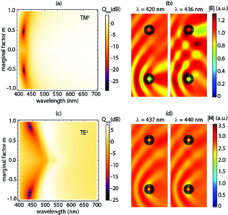
For the sake of illustration, in Fig. 2 we plot the efficiency spectrum , for wavelengths in the visible, of a nanotube which inmost radius is nm and thickness nm. The scattering efficiency is evaluated using Eq. (13) and the transfer-matrix formulation developed above. For TEz-polarized wave fields, the dynamical matrices given in Eq. (6) should include the transformation in agreement with the duality principle [17]. We initially assume a metallic layer width of nm and also a dielectric of width equal to 10 nm, so the metal filling fraction yields 0.5. The nanotube is immersed in air, where and also . For TMz polarized wave fields, two local minima in the scattering efficiency are found, as shown in Fig. 2(a): a first minimum for the marginal factor at nm, in which case the inmost and outermost silver layers approximately have a width of 5 nm each one, and a second minimum for at nm, where the inmost and outermost layers are made of titanium dioxide and also have a thickness of around 5 nm. This represents a substantial improvement of two orders of magnitude with respect to the case analyzed in Ref. [8], where the minimum in efficiency is found at nm. Fig. 2(b) shows the electric field scattered by two nanocavities, one with and the other one with , at the wavelengths of interest. It is demonstrated that our nanocavity with half-width marginal layers exhibits an extraordinary effect of invisibility () at the designer wavelength of nm, and in addition has a similar behavior () compared with the previously proposed nanotube at its best performance wavelength given at nm.
In the case that the incident field is a TEz-polarized plane wave, the resultant scattering efficiency of the nanotubes varies considerably as shown in Fig. 2(c). It is worth noting the nearly symmetric response of with respect to the sign of the factor , providing an analogous spectrum when the marginal layers are made of either TiO2 or silver, independently of the modal polarization under consideration. Now the minima are found for a marginal factor at nm, where , and for giving at nm. Note that Kim et al reported a scattering cancellation effect giving at nm, when we take into account 6 layers and the inmost layer is made of silver (). Again, our approach provides a remarkably decrease in scattering efficiency, as illustrated in Fig. 2(d) comparing the wave fields scattered by those two nanocylinders ( on the top and on the bottom) set together.
4 Discussion
The interpretation of such significant reduction in scattering may be carried out, at least partially, in terms of the effective medium theory. For sufficiently narrow slabs (), a radially form birefringence may be established for the metamaterial composed of concentric multilayers [21, 22]. In this case, TMz-polarized fields behave like ordinary waves propagating in a uniaxial crystal with optic axis set along the radial coordinate [23]. Waves propagate through the metallodielectric metamaterial with negligible variation of the electric field , a fact that in addition is in agreement with the electrostatic limit. However, the electric displacement undergoes critical discontinuities at the metal-dielectric interfaces. In average, decreases when the metal filling fraction grows, even vanishing in the so-called epsilon-near-zero regime, due to the negative value of the real part of [24]. The -component of the effective permittivity of the layered metamaterial may be estimated accordingly as
| (16) |
The definition of the weight averaged is intuitive, and refined analyses may be found elsewhere [25]. On the other hand, TEz-polarized fields propagate inside the multilayered metamaterial in the same manner as extraordinary waves, where the radial anisotropy is characterized by an average permittivity of components (that coincides with ) and , the latter taking much higher values than the former [8].
Equation (16) yields exactly the well-known expression , associated with the component along the perpendicular direction of the optic axis of the permittivity tensor , in a Cartesian coordinate system, of a form-birefringent metamaterial [23], only in the particular case that , that is for half-width marginal layers. Otherwise, the average permittivity critically depends on the inmost radius and the marginal parameter ; only when the shell is sufficiently narrow, , enabling the limit , the average permittivity reduces to in all cases. On the other hand, further symmetries may be found when the definition of the average permittivity given in Eq. (16) is applied to a metal-dielectric periodic nanocavity. In particular, depends on the absolute value of the marginal parameter . Since the scattering spectra shown in Fig. 2(a) and (c) also exhibit such a symmetry, we potentially may establish a correlation of the location of spectral peaks and valleys in terms of the average permittivity.
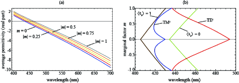
In Fig. 3(a) we plot the real part of the average permittivity evaluated in an Ag-TiO2 cylindrical cavity with inmost radius nm, thickness nm, period nm, metal filling fraction , and varying marginal factor . The average permittivity increases for higher and reaches its maximum value at for the whole spectral range. For instance, the condition , where the average permittivity of the multilayered nanotube matches the permittivity of the core and the environment medium, is attained at nm for and shifts to longer wavelengths for different marginal factors up to nm for . As illustrated in Fig. 3(b), such permittivity matching is behind the invisibility effect observed when the incident plane wave is TMz polarized, at least for moderate (and high) for which presents its minima in efficiency. In the near-optimal case where , is attained at nm, very close to the dip shown in Fig. 2(a) at nm. However, the effective medium approximation evidences remarkable limitations. For instance, there exists critical deviations of the condition and the loci of minima in for low . More importantly, it cannot predict the extraordinary scattering reduction for marginal factors around , in comparison with other configurations.
The scene is even more intricate for scattered fields under TEz polarization. The minima of the spectral scattering are blue-shifted along with higher values of , just advancing to the opposite direction with respect to any iso-permittivity curve with invariant (). Such severe deviations then put into question the validity of the effective medium theory as an appropriate approach to describe the invisibility effect observed here. Specifically at the minimum dB found at nm for , the effective permittivity rises to . In practical terms, we might affirm that the invisibility regime is established for marginal factors in the range occurring in the spectral band that satisfies .
Let us point out that, in one side, the existence of a peak near the scattering minimum in every spectra for this specific polarization suggests the occurrence of an isolated Fano resonance [26]. As a consequence of the resonant mechanism of invisibility, it is expected a dramatic impact on external factors such as the permittivity of the core and the environment medium, and also structural aspects such as scale and internal architecture of the nanocavity. On the other hand, nonlocalities that are inherent in metal-dielectric nanostructures, specially under TEz polarization [27], lead for instance to edge effects that seems to be behind an anomalous behavior out of the long-wavelength approximation, as highlighted in Ref. [12].
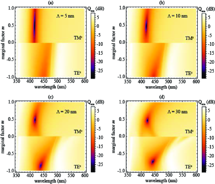
We may obtain further and revelatory conclusions by evaluating the scattering efficiency of our Ag-TiO2 nanotube of nm for different number of periods. In Fig. 4 we graphically represent the spectrum of for nanotubes with , 3, 6 and 12 periods. For the smallest period, nm, the marginal factor has a limited influence on the scattering spectrum, as expected; the long-wavelength approximation is valid in this case, and the nanotube might be considered as a radially-anisotropic medium. For TMz-polarized wave fields, the minimum of scattering efficiency reaches at nm. On the other hand, the scattering efficiency rises significantly when the polarization of the incident plane wave is TEz, for which a minimum value of at nm, representing a difference of nearly two orders of magnitude. Note that such nanostructure embodies a technological challenge since it takes into account a large number of Ag and TiO2 layers, each one with a layer width of 2.5 nm. When the period increases to nm, the impact of the marginal factor is evident as a direct result of nonlocal effects. In this case, the minimum efficiency for TMz-polarized fields, , is attained at nm (for ), manifesting a negligible variation in comparison with the previous case. For TEz polarization, the invisibility effect clearly improves in the limiting marginal factor , for which minimum scattering efficiency got at nm. On the other extreme, when the period nm, the minima in scattering efficiency are of the same order for both polarizations. For TMz-polarized fields we have a minimum at nm and , whereas for TEz polarization the minimum is found at nm for , providing a good performance in the first case and the best invisibility behavior in the latter. In addition, this sort of nanotube with the longest period manifests certain advantages from the practical point of view, such as the reduced number of layers (only 5) with widths of 15 nm except for the margins. As a consequence, from now on we consider Ag-TiO2 nanotubes of a period nm.
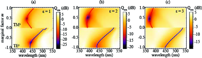
The influence of cores and environment media with different permittivities is examined in Fig. 5, for the same Ag-TiO2 nanotube described above. For brevity we analyzed the case where the dielectric constants and have the same value. For TMz-polarized incident light, a dramatic drop in the scattering efficiency is again observed but at lower wavelengths when the permittivity (and ) increases. In fact, to find the minimum of , the index matching condition may be established as in agreement with the shift undergone by the invisibility wavelength at every marginal factor, that is an extremely accurate approach for moderate and high . The lower difference between the permittivity of the dielectric part of the metamaterial and that of the external material, and respectively, requires of a metal with a permittivity also approaching which occurs closer to the plasma frequency [4]. Importantly, the optimal geometrical configuration is found for a marginal factor around 0.5 in all cases. As an example, a minimum of is found at nm for when the permittivity of the environment medium is set as .
On the other hand, the scattering efficiency dramatically increases for TEz-polarized wave fields. The loci of minima in practically remain in the same spectral band, slightly shifted to longer wavelengths at higher-index core and environment medium, demonstrating a high robustness under changes in the permittivity . However, their efficiencies increase several orders of magnitude. Taking for instance, is the minimum efficiency which is found at nm and . The wavelengths where minima of are located for TEz-polarized fields seem to be essentially determined by the opto-geometrical characteristics of the nanocavity thus being barely unaltered under changes in the environment; however, this is not longer valid for exceptionally-higher values of the index of refraction and significant deviations might be found [26]. This confirms the resonant behavior of the invisibility effect sustained in TEz-polarized wave fields, differently from scattered TMz-polarized waves
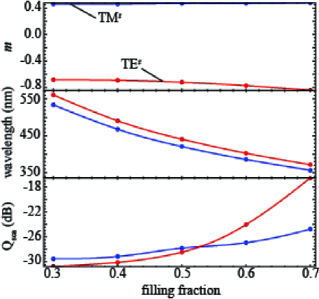
In Fig. 6 we consider nanotubes of different metal filling fractions , but maintaining a nanostructure of period nm; again the inmost radius nm and the nanotube thickness nm, but the marginal factor is varied to minimize the scattering efficiency. A permittivity of unity is set for the core and environment medium in the estimation of . The invisibility wavelength in the optimal configuration decreases 200 nm approximately, for both polarizations concurrently, when varies between 0.3 and 0.7. This fact suggests a means of tuning the invisibility spectral band of the multilayered scatterers [8]. For TMz-polarized scattered fields, the undertaken optimization leads to nanocylinders with marginal factors of modulus around 0.5, which provide scattering efficiencies below -25 dB in the range between and 0.7. On the other hand, the scattering efficiency is reduced to some extent when the incident plane wave is TEz polarized, at least for the lowest values of . This most favorable arrangement happens for nanostructures where the inmost silver layer is considerably wider than the outer layer giving marginal factors neighboring -0.8. However, cannot decrease and even reach the limit of -20 dB for the top range of filling fractions, which in principle has no critical impact in the tunability of the invisibility spectral band of the nanotubes expect maybe in ultrasensitive applications.
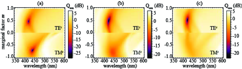
The size of the metallodielectric nanocavity might be essential concerning the applicability of the effective medium approximation in TMz-polarized wave fields, and more critically the resonant behavior of the nanotube for TEz polarization. In Fig. 7 we plot the scattering efficiency of Ag-TiO2 multilayered nanoshells with different radii immersed in air. We maintain the scatterer thickness nm, period nm, metal filling fraction , and we change the marginal factor in order to find the configuration with optimal scattering cancellation. For TMz polarized fields, the plots remain practically unaltered for inmost radius ranging from nm up to nm. Limited deviations are attributed to the reduced dependence of on in spite of the considerable difference in size of the cylindrical scatterers. Considering now scattered fields under TEz polarization, the efficiency pattern is modified significantly. The minimum in scattering efficiency changes from for nm as discussed above, increasing to for nm that is found at nm when , and reaching for nm (at nm and ). For this specific polarization, the capacity of the nanotubes for canceling the scattered wave field, within the spectral band of interest, decays progressively when the radius grows certainly due to the existence of multiple localized resonances that are associated with whispering-gallery modes. On the other hand, note that for radius in the micro-scale, such optical microcavities with whispering-gallery modes have stimulated multifunctional applications to optofluidic devices such as microlasers and bio/chemical sensors [28].
5 Conclusions
The study carried out here shows the route for the optimal utilization of the marginal layers in metal-dielectric multilayered nanotubes as invisible conducting scatterers within a tunable spectral band. We utilize the inherent nonlocal effects of metallodielectric nanostructures in support of a drastic reduction of the scattered signal of the designer cylindrical nanocavity. Our approach leads to a drop of the nanoparticle scattering efficiency that may reach up to two orders of magnitude in comparison with previous proposals also based on radially-periodic arrangements. The remarkably invisibility of our Ag-TiO2 nanotube is largely ascribed to scattering cancellation for TMz-polarized incident plane waves and a Fano-type isolated resonance for TEz-polarized fields. The resonant behavior of the nanotubes in TEz polarization configurations made it reducing the maximal efficiency to changes in the external environment, diameter of the nanoparticle and even the period of the metamaterial. Although the cylindrical cavity has a polarization-selective response, it can be adjusted to present a significant reduction of the scattering efficiency simultaneously for both polarizations. Importantly, the Lorenz-Mie scattering coefficients are set in terms of a transfer matrix formalism leading to the fast evaluation of the scattering efficiency of the multilayered nanocavity. We believe that the use of invisible conducting nanocavities for invisible electrodes and waveguides presents a promising strategy toward next-generation optofluidic and sensing.
Acknowledgments
This work was supported by the Spanish Ministry of Economy and Competitiveness (MINECO) (TEC2014-53727-C2-1-R)