Closed-loop focal plane wavefront control with the SCExAO instrument
Abstract
Aims. This article describes the implementation of a focal plane based wavefront control loop on the high-contrast imaging instrument SCExAO (Subaru Coronagraphic Extreme Adaptive Optics). The sensor relies on the Fourier analysis of conventional focal-plane images acquired after an asymmetric mask is introduced in the pupil of the instrument.
Methods. This absolute sensor is used here in a closed-loop to compensate the non-common path errors that normally affects any imaging system relying on an upstream adaptive optics system.This specific implementation was used to control low order modes corresponding to eight zernike modes (from focus to spherical).
Results. This loop was successfully run on-sky at the Subaru Telescope and is used to offset the SCExAO deformable mirror shape used as a zero-point by the high-order wavefront sensor. The paper precises the range of errors this wavefront sensing approach can operate within and explores the impact of saturation of the data and how it can be bypassed, at a cost in performance.
Conclusions. Beyond this application, because of its low hardware impact, APF-WFS can easily be ported in a wide variety of wavefront sensing contexts, for ground- as well space-borne telescopes, and for telescope pupils that can be continuous, segmented or even sparse. The technique is powerful because it measures the wavefront where it really matters, at the level of the science detector.
Key Words.:
instrumendation – adaptive-optics1 Introduction
Several approaches to high contrast imaging have now clearly demonstrated the power of focal-plane based image analysis. Most prominently, non redundant aperture masking (NRM) interferometry (Tuthill et al., 2000), relying on interferometric calibration tricks in the focal plane has led to high contrast detections (of the order of 1000:1) in a regime of angular separation (typically between 0.5 and a few ) that is still unmatched in practice by techniques like coronagraphy (Kraus & Ireland, 2012; Sallum et al., 2015). As the generation of extreme adaptive optics (XAO) instruments is coming on-line, more advanced wavefront control schemes developed in the context of space-borne coronagraphy like speckle nulling (Bordé & Traub, 2006) or the general framework of electric field conjugation (Give’On, 2009) are being ported on-sky (Martinache et al., 2014; Cady et al., 2013). Nevertheless, it remains remarkable that such a venerable approach (the original masking idea by Fizeau was indeed first tested in the 1870s), has remained relevant for well over a century. This is really a tribute to the deep understanding that interferometry has brought to the process of image formation.
It was more recently shown that the same self-calibrating tricks used in masking interferometry, could in fact be applied to regular (i.e. unmasked) images, assuming AO-correction with residual wavefront errors radian RMS. The notion of closure-phase (Jennison, 1958), was indeed generalized and shown to be a special case of a wider family of self-calibrating observables coined kernel-phases (Martinache, 2010), since they form the basis for the null-space (or kernel) of a linear operator. This generalization also opened the way for a focal-plane based wavefront sensing approach, relying this time on the eigen-phases of the same linear operator. While this problem is generally degenerate, one way to break this degeneracy proved to be simple, and involved masking a small but non negligible fraction of the pupil to introduce some level of asymmetry. The principles of this asymmetric pupil Fourier wavefront sensor (APF-WFS) were described by Martinache (2013), and exploited by Pope et al. (2014) to show how it could be used, for instance, to cophase a segmented mirror. This paper further expands on the possible applications of this wavefront sensor, as it is now implemented as part of the SCExAO instrument (Jovanovic et al., 2015b), to compensate for a non-common path error unseen by its upstream pyramid wavefront sensor.
2 Implementation of closed-loop wavefront control
2.1 Theoretical principle of APF-WFS
The APF-WFS method relies on the analysis of the Fourier properties of an AO-corrected image acquired after an asymmetric hard-stop mask has been placed in the pupil. The SCExAO instrument is equiped with two such masks with the asymmetric feature at distinct position angles, so that every part of the instrumental pupil can be accounted for. A rotation wheel, located in a plane conjugated with the pupil of the instrument (cf. Figure 3 of Jovanovic et al. (2015b)) makes it possible to move the masks in and out of the beam as required by the observer.
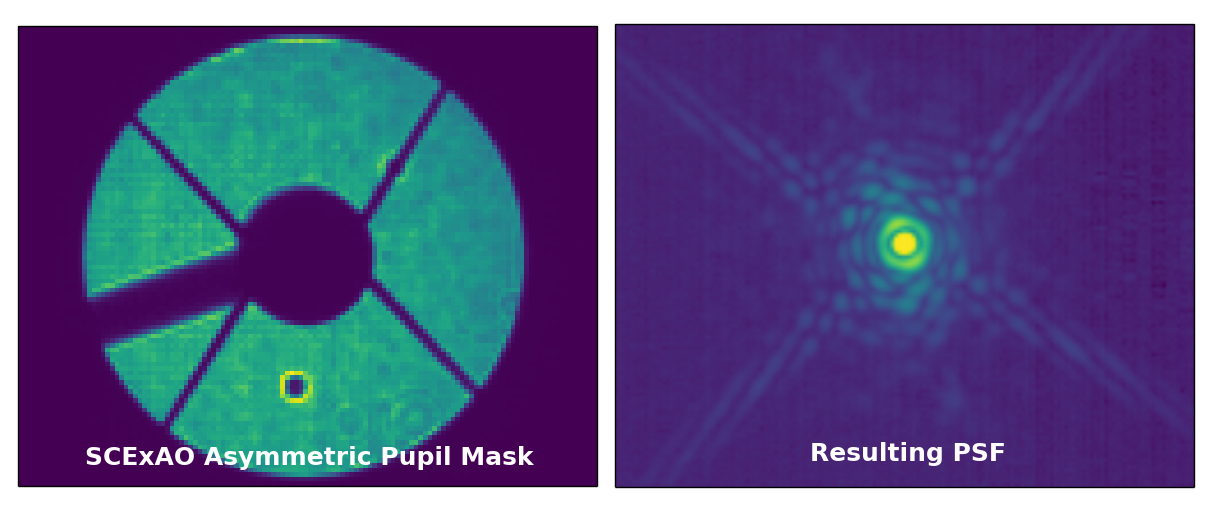
Figure 1 shows an image of one of the asymmetric masks in the pupil and the point spread function (PSF) it produces. Combined with the use of the 2000-element deformable mirror (DM), this simple alteration of the pupil is a powerful tool used to control the low-order aberrations of the instrument PSF. All images featured in this paper were acquired using a H-band filter, centered on wavelength 1.65 m and with an effective bandwidth 0.3 m. The pixel scale of the internal science camera is 12.1 mas per pixel, which for this wavelength, provides a sampling better than Nyquist.
It was shown that, in the low-aberration regime, typical of what is left over after a first layer of AO correction is applied, the phase measured in the Fourier transform of an image and the instrumental pupil phase are linearly related. On the internal calibration source, unaffected by atmospheric turbulence, the Strehl of images used in this study (such as during the calibration) is typically of the order of 80%. On-sky, since the results featured here were acquired before the XAO loop is closed, the Strehl is significantly lower, of the order of 50 %, which is a sufficiently good starting point for approximation to be valid.
The target phase information, associated with the spatial structures of the observed object , is also present in the Fourier plane and simply adds to this instrumental Fourier phase. When wavefront aberrations are low (below 1 radian), the classical image-object convolution relation:
| (1) |
can therefore be reformulated, if one works with the phase part of the Fourier transform of this image as follows:
| (2) |
where is an operator that describes the way the pupil phase propagates into the Fourier-plane.
When observing a point source, for which (or if the object is known), this relation can be inverted if one introduces an asymmetry in the pupil (Martinache, 2013). A direct focal plane image, with only a small amount of additional diffraction generated by the pupil asymmetry (cf. Figure 1), can therefore serve as a wavefront sensor.
To determine the structure of the operator , one needs to build a
discrete representation of the instrument pupil - including the asymmetric mask
- following a regular grid with a step such that the sampling density is
reasonably representative of the original pupil. One then looks at the way
this discrete model projects into equivalent interferometric baselines in the
Fourier plane. The model currently used on SCExAO is provided in
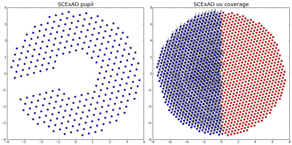
Figure 2. It reduces the masked pupil to a 292-component vector that
projects onto a 675-element vector in the Fourier domain. The phase transfer
matrix that establishes the mapping between the two spaces () is calculated using the PYSCO software,
used for wavefront sensing as well as for kernel-phase data analysis of
diffraction limited images.
The presence of the asymmetry in the pupil ensures that an inverse relation for this phase transfer matrix exists, and can be used to infer the pupil phase vector from the Fourier phase , using the relation:
| (3) |
where is a Moore-Penrose pseudoinverse of the phase transfer matrix , computed after rejecting modes associated to low singular values. The geometry of the asymmetric feature of the mask used for this work is not the result of an optimization and simply follows the shape used in the concept paper of Martinache (2013). One would expect that a smaller asymmetry should result in a lower sensitivy but a systematic study of the sensitivity impact of the geometry of the asymmetry has yet to be done. In the mean time, the curious reader should check the experimental work of Pope et al. (2014), that shows that, in the case of a segmented aperture, the technique remains effective, even with a minimum of asymmetry (a single segment of the aperture) and suddenly breaks, if no asymmetry is present at all, validating the mathematical model this approach relies on.
2.2 Integrating a real system
The case featured in (Martinache, 2013) was somewhat idealized, working on monochromatic images, and with a perfect DM, able to exactly generate the wavefront correction determined by the analysis. To deploy this method on an actual closed-loop system is not as direct and requires us to take into account the actual properties of the DM, such as the response curve of the actuators, their influence functions, as well as a careful mapping of these DM actuators on the instrument pupil (Blain, 2013). While possible, one such model is very prone to errors and its maintenance is demanding, because of small changes in the internal instrument alignment induced by temperature drifts or after a telescope slew.
AO systems in operation usually choose to rely on a more pragmatic approach that encapsulates this kind of model in a transparent manner: individual DM actuators or groups of actuators (pre-defined modes) are sequentially excited and the system response is recorded and assembled in a matrix. Filtering of the noisy modes before inversion (using SVD or similar procedures) leads to the obtention of a control matrix that can be used to directly multiply an input vector made of the wavefront sensor raw input data.
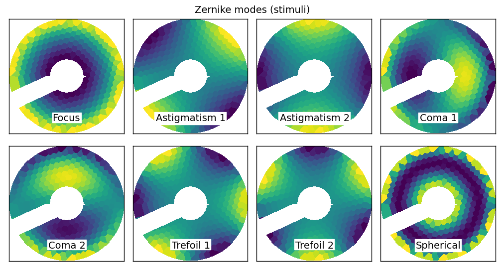
This pragmatic approach is the one that was retained for this implementation of APF-WFS. The control software was designed to sense and control eight low-order Zernike modes (Zernike, 1934) that correspond to classical optical aberrations: focus, two terms of coma, astigmatism and trefoil, and spherical aberration. Figure 3 shows how these modes map on the discrete pupil model used to describe the instrument.
2.3 Properties of the phase transfer model
To better appreciate the impact of the phase transfer model, one can look at the effect of the projection in the Fourier plane and then back in the pupil plane, using the linear relations of Eq. 2 and Eq. 3. The original phase becomes:
| (4) |
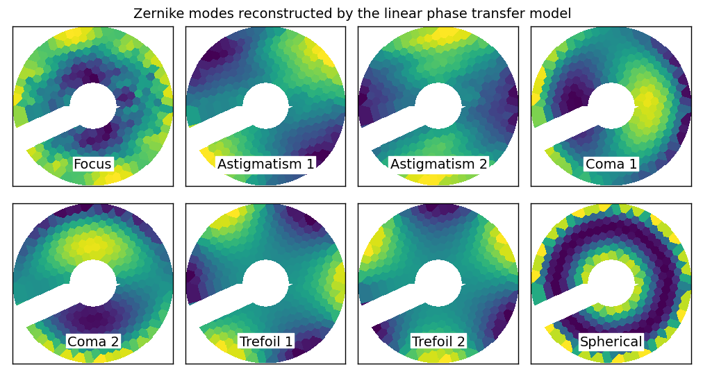
Depending on the number of modes kept in the determination of the pseudo-inverse of the phase-tranfer matrix, the reconstruction goes from perfect (if all modes are preserved) to very partial (if few modes are preserved). The modes discarded correspond to low singular values, which for a given level of signal-to-noise in actual data, would result in amplified noise. On SCExAO, for the control of these eight low-order modes, 150 out of the 291 available modes are maintained in the computation of the pseudo inverse. Under these conditions (cf. Figure 4), the reconstruction appears satisfactory, and confirms that the technique can indeed be used to control low-order modes, assuming that the linear model holds (and that aberrations are small).
2.4 Calibration
The calibration procedure for this implementation of the APF-WFS follows the linear control framework. After the asymmetric mask has been inserted, one acquires one image labeled as reference, followed by a sequence of images acquired after a Zernike mode of appropriate amplitude has been applied to the DM. Figure 4 features one such calibration data-set, acquired with the focal camera of SCExAO on its internal calibration source (super-continuum laser) using a standard H-band filter, for a 30 nm RMS deformation of the DM. Note that this displacement actually translates into a 60 nm wavefront amplitude modulation (the DM being a reflective system).
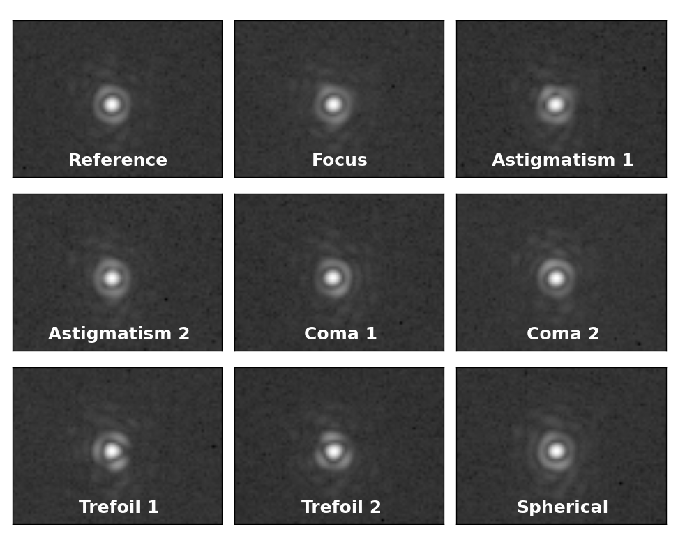
Each image is recentered and windowed by a super-gaussian function that filters out high-spatial frequencies, and reduces the impact of detector readout noise. It is then Fourier-transformed and the Fourier-phase is extracted according to the sampling model featured in the right hand side of Figure 2 to populate a vector .
To each Zernike mode, one can therefore associate a Fourier-phase vector after subtracting the phase measured in the initial or reference state:
| (5) |
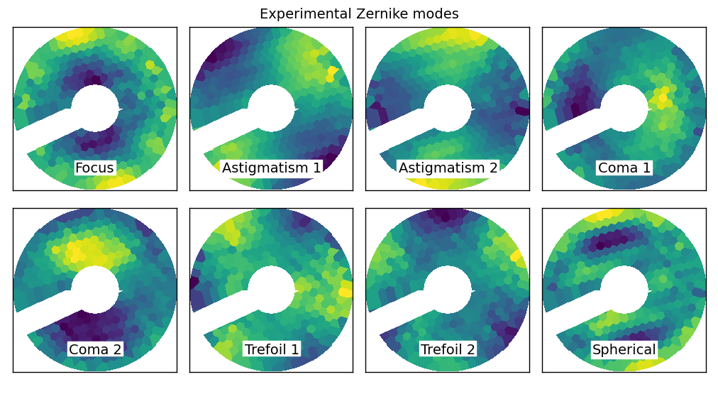
The wavefront associated to this Fourier-phase signature can be recovered using the pseudo-inverse previously computed and applying Eq. 3. This wavefront in radians can in turn be converted into a DM displacement map (in microns) after being multiplied by the proper scaling factor; where is the wavelength expressed in microns and contains the 2 factor due to the reflection. Figure 6 features an example of experimentally recovered modes. One will observe that the reconstruction from the Fourier analysis of actual images appears visually satisfactory. Differences in the reconstruction with the modes plotted in Figure 4 can be attributed to imperfections of the pupil discretization model (cf. Figure 4 of Martinache (2013)), combined to practical subtleties like the fact that the dynamical range on the camera is limited and that classical noises: photon and readout, do apply.
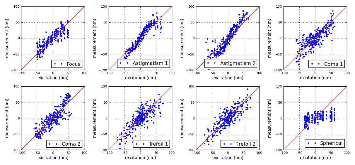
To complete this description of the general aspect of the modes with a quantitative estimate of the quality of the reconstruction, Figure 7 directly compares the experimental reconstruction to the theoretical Zernike modulation , by plotting the local deduced DM displacement against its predicted value. One can confirm that all modes are not equally reproduced by the analysis, and that for this experimental setup, the sensor is most sensitive to astigmatism (for which the correlation coefficient is the strongest) and not particularly suited to the sensing of spherical aberration. Table 1 accompanies this figure and provides the value of the Pearson product moment correlation coefficient for all modes:
| (6) |
| Zernike Mode | quality |
|---|---|
| Z4 (focus) | 0.855 |
| Z5 (astigmatism 1) | 0.949 |
| Z6 (astigmatism 2) | 0.925 |
| Z7 (coma 1) | 0.820 |
| Z8 (coma 2) | 0.862 |
| Z9 (trefoil 1) | 0.827 |
| Z10 (trefoil 2) | 0.854 |
| Z11 (spherical) | 0.522 |
Table 1 also shows that with a correlation coefficient 0.5, spherical aberration is significantly less well reconstructed than the other modes that exhibit correlation coefficient 0.8. The specificity of the response to spherical aberration is however not an intrinsic limit of the sensing approach and can in fact simply be explained by the 2D geometry of this aberration and how it fits within the footprint of the Subaru Telescope and its large (30% central obstruction). By looking, for instance at Figure 3, one will observe that the donut shape of the spherical aberration results in a pretty uniform distribution of the phase, that only varies near the inner and outer edges of the pupil. The basis of Zernike polynomials is defined for a complete circular aperture: quoted amplitudes correspond to a given wavefront RMS over the entire circular aperture. For the spherical aberration, the presence of the central obstruction naturally filters a lot of the effect of the spherical aberration. This is further confirmed after a close examination of scatter plots of Figure 7: whereas all Zernike stimuli (along the horizontal axis of the plots) have the same amplitude, one will observe that the resulting range of local DM displacement (corresponding to the horizontal spread of the data points) is appreciably shorter for the spherical aberration than it is for the other modes.
These experimentally obtained pupil-phase modes are stored in a matrix , refered to as the response matrix. In practice, unless the DM registration were to change in a dramatic manner, the calibration is quite robust: a response matrix acquired using the internal calibration source and can be very well be used during on-sky observations, if the filter remains unchanged and if the change of exposure time does not result in a saturated PSF core (cf. the discussion in Section 4).
On SCExAO, the acquisition of this response matrix only takes a few seconds, so it can easily be repeated if needed after acquisition of a new target. In practice, it seems a response matrix acquired on the stable internal calibration source provides the best results.
2.5 Closed-loop operation
Just like during the calibration, focal-plane images acquired on-sky with the asymmetric mask are dark-subtracted, recentered and windowed by a super-gaussian function before being Fourier-transformed. After extraction of the Fourier-phase, a wavefront is produced and directly projected onto the basis of modes (without subtracting the reference), to find the coefficients associated to all eight Zernike components. If the current wavefront sensor signal is , the instant Zernike coefficients are the solution of . The least square solution of this system is the solution to:
| (7) |
The solution to this well behaved system of equations is used as an input for a control loop algorithm. The loop in operation on SCExAO implements a simple proportional controller, with a gain common to all Zernike modes with value contained between 0.05 and 0.3, depending on the overall stability of the wavefront provided by the upstream AO. When looking at the internal calibration source, one can reliably use the highest gain. Since it is for now only used for a very short time (typically seconds), at the time of target acquisition to flatten the static component of the wavefront, the current implementation of the algorithm is proving satisfactory. Once the non-common path error is accounted for, the asymmetric mask is taken out of the optical path and the system is ready for observing using the full pupil of the telescope.
3 Performance
3.1 On-sky demonstration
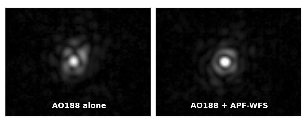
The technique was successfully deployed and proved to be effective at reducing the non-common path error during on-sky observations behind Subaru Telescope’s facility AO system AO188 (Minowa et al., 2010). Figure 8 illustrates the impact of the approach, with two 500 s exposures of the target (Altair) acquired by SCExAO’s internal science camera on UT 2015-10-30.
The first image shows the PSF after the AO188 loop has been closed on the target: although it features a well defined diffraction core, the PSF clearly exhibits some static aberrations that can be attributed to the non-common path error between AO188 and SCExAO’s focal plane. The second image shows the PSF about 30 seconds after the APF-WFS loop has been closed. The gain in Strehl is low (of the order of 5 %), but the PSF is improved at where it matters most for high contrast imaging and no longer features any obvious low-order aberration signature. Residual inhomogeneity of the first diffraction ring can be attributed to a combination of instantaneous AO residuals combined with the effect of the asymmetric arm.
SCExAO’s internal science detector is a fast but low-sensitivity detector that can acquire images at up to 170 Hz full-frame rate whose specifications are given in (Jovanovic et al., 2015b). APF-WFS seems to exhibit sufficient sensitivity to be used in a fast closed-loop that could very well track low-order aberrations with frequencies up to a tenth of the camera frame rate.
At the moment, the goal of the loop is to calibrate the quasi-static non-common path error. The control software keeps a rolling average of the 20 last wavefront estimations, and corrects for the average of these estimations at each iteration, thus filtering vibration-induced fast varying component. Combined to the acquisition, the (non-optimized) computation of the wavefront makes the loop run at a frequency of 8 Hz.
3.2 Cross-talk
Zernike polynomials (Zernike, 1934) form a convenient basis to describe a wavefront within a circular aperture: designed to form an orthonormal basis, the first terms of the series happen to correspond to classical monochromatic optical aberrations like focus, astigmatism or coma. As previously seen, the presence of a central obstruction in the pupil makes this basis no longer perferctly orthogonal. Substitutes have been proposed (Mahajan, 1981) in order to accomodate for the presence of this rather common feature of telescopes, but the asymmetric arm required for the wavefront sensing (cf. Section 1) would also require an adaptation.
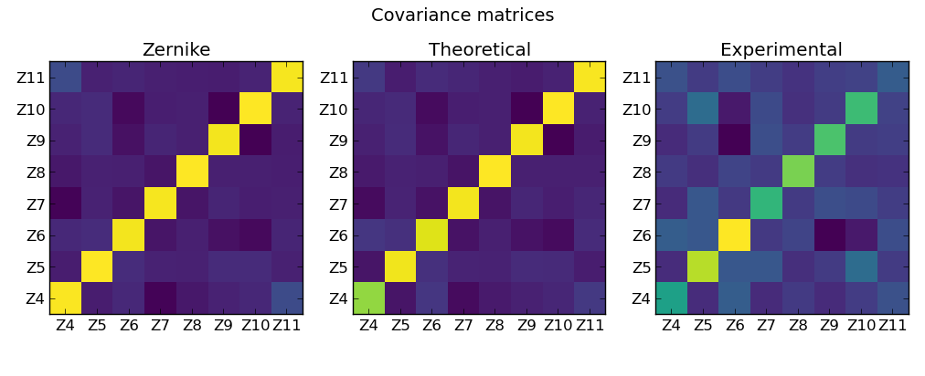
Instead of trying to specify a new orthogonal basis perfectly adapted to our case, we have judged more appropriate to stick to the conventional Zernike basis, and verify a posteriori how orthogonal the different modes actually are. Figure 9 does this by plotting the matrix of inner products between the eight control modes () for three cases: the input Zernike polynomials (given in Figure 3), the theoretical reconstruction of the linear model with 150 out of the 291 eigen modes kept in the phase transfer matrix inversion (given in Figure 4) and the experimentally acquired modes (given in Figure 6).
An orthogonal basis will result in a perfectly diagonal inner-product matrix whereas non-orthogonality would become manifest with strong non-diagonal components.
One can therefore observe, looking at the left hand side panel of Figure 9, that the Zernike modes do form a satisfactory, nearly orthonormal basis, with a mostly uniform diagonal and a limited amount of cross terms standing out (except for the case of the 16% cross-correlation between focus (Z4) and spherical (Z11). For the sake of consistency with the rest of the data presented in the paper, Figure 9 also shows in its central panel, that the modes reconstructed by the linear model reproduce most of these features, although one can observe 20% degradation of the relative strength of the focus signal. What we observe here is the effect of the filtering of low singular values in the construction of the pseudo-inverse as used in Equation 4. With 150 out of the possible 291 modes kept in the construction of the pseudo-inverse, the inner product matrix for the experimentally recovered modes is also mostly diagonal.
Table 2 provides the numerical values for the experimental inner products, also graphically represented in the right hand side panel of Figure 9. Although some of the cross terms are non-neglibible, the terms along the diagonal still dominate, indicating that a control loop relying on this calibration dataset will reliably converge toward a state that will cancel the non-common path aberration.
| Z4 | Z5 | Z6 | Z7 | Z8 | Z9 | Z10 | Z11 | |
|---|---|---|---|---|---|---|---|---|
| Z4 | 0.46 | -0.09 | 0.12 | -0.10 | -0.04 | -0.09 | -0.03 | 0.06 |
| Z5 | -0.09 | 0.87 | 0.09 | 0.09 | -0.08 | -0.03 | 0.19 | -0.03 |
| Z6 | 0.12 | 0.09 | 1.00 | -0.04 | 0.01 | -0.25 | -0.16 | 0.05 |
| Z7 | -0.10 | 0.09 | -0.04 | 0.57 | -0.04 | 0.05 | 0.03 | -0.02 |
| Z8 | -0.04 | -0.08 | 0.01 | -0.04 | 0.75 | -0.03 | -0.07 | -0.07 |
| Z9 | -0.09 | -0.03 | -0.25 | 0.05 | -0.03 | 0.65 | -0.03 | -0.02 |
| Z10 | -0.03 | 0.19 | -0.16 | 0.03 | -0.07 | -0.03 | 0.61 | 0.00 |
| Z11 | 0.06 | -0.03 | 0.05 | -0.02 | -0.07 | -0.02 | 0.00 | 0.11 |
3.3 Range of linear response
As reminded in Section 2.1, the APF-WFS relies on the assumption that an upstream AO correction is provided. The system is expected to deal with with small residual wavefront errors, and the calibration procedure described above, typically employs DM modulation amplitudes of 30-50 nm. To determine the amount of aberration the technique is able to deal with, we performed a systematic exploration of the response of the sensor to stimuli of variable amplitude. The instantaneous response of the sensor is projected onto the basis of modes following the procedure outlined in Section 2.5. Figure 10 summarizes the result of this systematic exploration of the response of the sensor, over a 150 nm range of DM modulation amplitude.
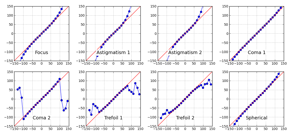
Although not perfectly linear, for Z4 (focus), Z5, Z6 (astigmatism), Z7 (coma 1) and Z11 (spherical), the response remains monotonic over the entire 150 nm range. For Z8 (coma 2), Z9 and Z10 (trefoil 1 and 2), the response is only monotonic over the 80 nm modulation range beyond which the sensor cannot be used reliably.
The drastic difference of response between Z7 and Z8 which correspond to the same type of aberration (ie. coma), can be explained by the azimuth of the asymmetric arm in the pupil stop, oriented such that it masks out almost entirely one of the two antisymmetric bumps that are characteristic of this aberration (cf. for instance the top-left most panel of Figure 3).
A strong non-linearity of the response is experienced when the pupil-phase peak-to-valley (P2V) wavefront becomes larger than 2 (which results in a phase wrap). The presence of the asymmetric stop at its current azimuth essentially divides the P2V by a factor of two in the case of Z7 (ie. coma 1), hence making the sensor able to handle twice as much coma along the horizontal axis than along the vertical axis. Note that the same effect (to a lesser extent) can also be observed when comparing Z9 and Z10.
We can nevertheless conclude that under normal operating conditions, in the H-band, the sensor is able to operate linearly as long as the RMS error on either mode is less than 200 nm on the wavefront.
4 Wavefront sensing from a saturated PSF
A well AO-corrected PSF is a highly contrasted object. The proper simultaneous sampling of the core of the PSF and its diffraction rings therefore requires a detector with a large dynamical range, that is rarely compatible with a fast readout. The SCExAO internal science camera has an effective dynamical range of 10000 counts, so that in practice, one has to choose an exposure time that either gives access to a non-saturated PSF core (the normal operating mode of the wavefront sensing approach described thus far) or over-expose the PSF core to better see the fainter diffraction structures that surround it.
In its general form, the linear model of Eq. 2 only holds when working on non-saturated images that otherwise result in a non-translation invariant PSF. Pixels that are saturated by the bright core of the PSF can be treated as zeros, so that the effect of saturation can be modeled as a multiplication by a top-hat function that cuts off anything higher than a level imposed by the characteristics of the detector. This multiplication in the image space, results in a convolution by an Airy-like function whose characteristic size is inversely proportional to the size of the saturated part of the PSF.
The effect of this convolution is expected to be most prominent in the outermost region of the Fourier plane where the phase will experience a change of sign. Figure 11 illustrates this effect by comparing the Fourier-phase signature of a specific aberration for a non-saturated PSF to that of a mildly saturated one. One can observe that while the outermost part of the Fourier-phase is obviously affected by the saturation, the innermost part of the PSF (highlighted by the smaller dashed circle) does resemble the original non-saturated case.
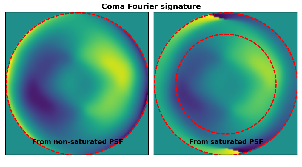
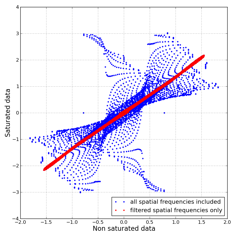
Figure 12 further makes this obvious by representing in a 1D plot the values of the Fourier-phase of the saturated image against the Fourier-phase of the non-saturated image. Whereas considered as a whole, the Fourier-phase of the saturated data appears as non-usable (the blue points are widely scattered), the inner part of this same saturated data set is strongly correlated (the red points) with the non-saturated data, suggesting that some of the wavefront information can be recovered in the saturated case, assuming that one filters out the information coming from the largest baselines.
To account for this filtering, the Fourier-phase model can be modified, and the parts of the phase transfer matrix can be discarded along with the parts of the Fourier-phase vector that are filtered out. The model we have tested only preserves baselines that are 70% or less than the longest baseline in the model, which corresponds to the area inscribed within the inner circle plotted in the right panel of Figure 11. Out of the 675 original distinct uv-phase samples, 330 remain with this configuration, which is still of the order of the number of modes one needs in order to recover the full theoretical pupil phase information (291 modes).
For the computation of the pseudo-inverse of this new system, 50 modes are kept. With less constraints from the uv-plane, the Zernike modes are less well reconstructed, but are nevertheless recognizable, as shown in Figure 13.
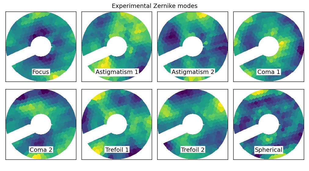
The calibration procedure introduced in Section 2.4 can be repeated with this new model after which, the APF-WFS is effectively able to operate in closed-loop from the analysis of saturated data, albeit with lower performance. To see how this saturation affects the sensor, the study presented in Section 3.3 was repeated in this new operating mode. The outcome of this study is presented in Figure 14.
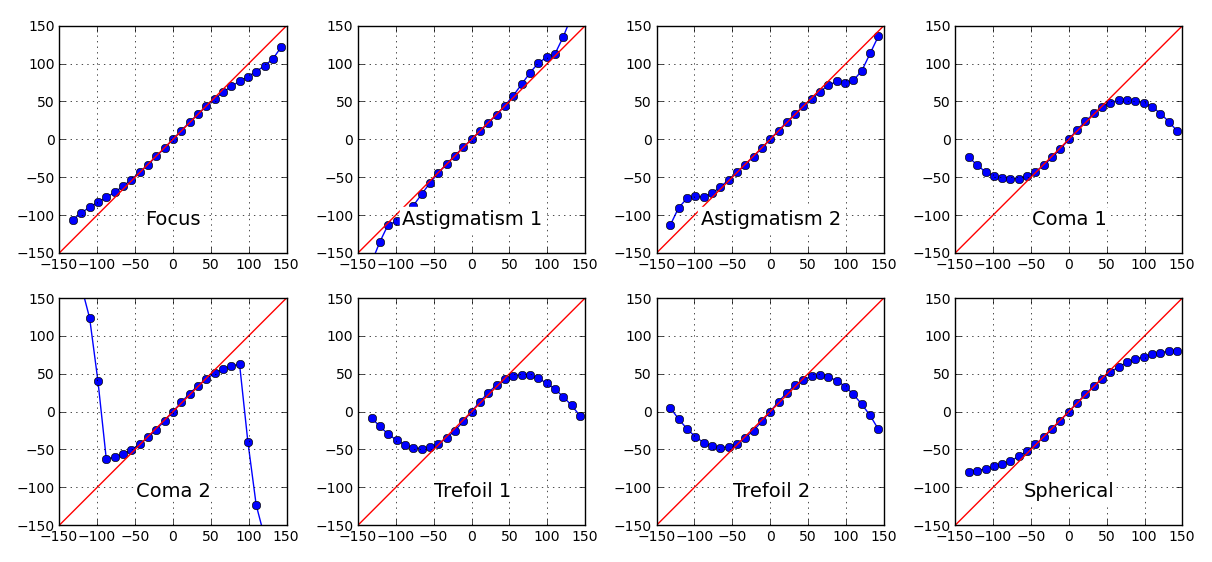
In this peculiar saturated mode, the sensor is able to operate linearly over a limited range of aberrations. Like previously observed (cf. Section 3.3), it is the modes whose geometry feature localized bumps like coma of trefoil that first limit the range of aberration that APF-WFS can account for. APF-WFS can nevertheless operate on images whose core is saturated, over a 100 nm wavefront RMS range that is roughly one half of what it can achieve in the non-saturated operating regime: the general APF-WFS approach is more robust than first expected and can be used despite less than ideal conditions.
5 Conclusion
Following on the conceptual study proposed by Martinache (2013), this paper described the implementation of the asymmetric pupil Fourier wavefront sensor as one of the wavefront control loops of the SCExAO instrument. This approach has proven able to repeatedly account for the non-common path error that affects the instrument after a new telescope pointing and provide an updated zero-point for the upstream pyramid wavefront sensor currently implemented inside SCExAO.
A surprisingly simple asymmetric hard stop mask introduced in the pupil of a diffraction limited imaging instrument is therefore proving to be a powerful diagnostic tool for the control of the non-common path aberrations. The reported capture range of the technique is currently limited to a fraction of a wave (RMS ). A combination of filters of decreasing wavelengths would provide a direct way to tolerate a cruder starting point. We are currently exploring the potential of an updated algorithm that simultaneously exploits the information sampled at multiple wavelengths to extend the capture range even more, this time within the coherence length. Note that other approaches using combinations of non-redundant aperture masks (Cheetham et al., 2012, 2014) also rely on this idea to extend their capture range.
The asymmetry results in slight cosmetic degradations of the PSF. While this does impact a coronagraphic instrument, it can be tolerated in a general purpose AO-corrected imaging instrument. A very interesting feature of this image-based wavefront sensing approach is that if multiple sources are available in a given field, the APF-WFS algorithm can be used on all sources simultaneously. Depending on the complexity of the field, the same asymmetric mask, combined with the analysis of multiple sources in one image can be used for multi-reference wavefront sensing, opening the way to a full 3D reconstruction of the wavefront from the analysis of a single focal plane image. This very property can also be put to use on artificially introduced incoherent replicas of an on-axis PSF, of tunable intensity as described by Jovanovic et al. (2015a), thus making the use of the technique compatible with that of a coronograph that otherwise destroys the interferometric reference required for a sensible Fourier-analysis of the image as described in this work.
The use of this wavefront control technique extends well beyond the control of low-order modes on SCExAO: this paper provides experimental evidence that the technique is actually effective where the theory predicts it should be. In an exposure that simultaneously features an unsaturated PSF core and the diffraction features at large separation with sufficient SNR, APF-WFS can be used to control an arbitrary number of modes, as was shown in the concept paper. APF-WFS can in fact easily be applied in a wide variety of wavefront sensing contexts, for ground- as well space-borne telescopes, and with a pupil that can be continuous, segmented or even sparse. APF-WFS is powerful because it measures the wavefront where it really matters, at the level of the science detector. Given its low impact on the instrument hardware, it is an option that should be given some consideration, as part of any high contrast imaging instrument with wavefront control capability.
References
- Blain (2013) Blain, C. 2013, PhD thesis, University of Victoria (Canada
- Bordé & Traub (2006) Bordé, P. J. & Traub, W. A. 2006, ApJ, 638, 488
- Cady et al. (2013) Cady, E., Baranec, C., Beichman, C., Brenner, D., Burruss, R., Crepp, J., Dekany, R., Hale, D., Hillenbrand, L., Hinkley, S., Ligon, E. R., Lockhart, T., Oppenheimer, B., Parry, I., Pueyo, L., Rice, E., Roberts, L. C., Roberts, J., Shao, M., Sivaramakrishnan, A., Soummer, R., Tang, H., Truong, T., Vasisht, G., Vescelus, F., Wallace, J. K., Zhai, C., & Zimmerman, N. 2013, in Proc. SPIE, Vol. 8864, Techniques and Instrumentation for Detection of Exoplanets VI, 88640K
- Cheetham et al. (2014) Cheetham, A., Cvetojevic, N., Norris, B., Sivaramakrishnan, A., & Tuthill, P. 2014, Optics Express, 22, 12924
- Cheetham et al. (2012) Cheetham, A. C., Tuthill, P. G., Sivaramakrishnan, A., & Lloyd, J. P. 2012, Optics Express, 20, 29457
- Give’On (2009) Give’On, A. 2009, in Proc. SPIE, Vol. 7440, Techniques and Instrumentation for Detection of Exoplanets IV, 74400D
- Jennison (1958) Jennison, R. C. 1958, MNRAS, 118, 276
- Jovanovic et al. (2015a) Jovanovic, N., Guyon, O., Martinache, F., Pathak, P., Hagelberg, J., & Kudo, T. 2015a, ApJ, 813, L24
- Jovanovic et al. (2015b) Jovanovic, N., Martinache, F., Guyon, O., Clergeon, C., Singh, G., Kudo, T., Garrel, V., Newman, K., Doughty, D., Lozi, J., Males, J., Minowa, Y., Hayano, Y., Takato, N., Morino, J., Kuhn, J., Serabyn, E., Norris, B., Tuthill, P., Schworer, G., Stewart, P., Close, L., Huby, E., Perrin, G., Lacour, S., Gauchet, L., Vievard, S., Murakami, N., Oshiyama, F., Baba, N., Matsuo, T., Nishikawa, J., Tamura, M., Lai, O., Marchis, F., Duchene, G., Kotani, T., & Woillez, J. 2015b, PASP, 127, 890
- Kraus & Ireland (2012) Kraus, A. L. & Ireland, M. J. 2012, ApJ, 745, 5
- Mahajan (1981) Mahajan, V. N. 1981, Journal of the Optical Society of America (1917-1983), 71, 75
- Martinache (2010) Martinache, F. 2010, ApJ, 724, 464
- Martinache (2013) —. 2013, PASP, 125, 422
- Martinache et al. (2014) Martinache, F., Guyon, O., Jovanovic, N., Clergeon, C., Singh, G., Kudo, T., Currie, T., Thalmann, C., McElwain, M., & Tamura, M. 2014, PASP, 126, 565
- Minowa et al. (2010) Minowa, Y., Hayano, Y., Oya, S., Watanabe, M., Hattori, M., Guyon, O., Egner, S., Saito, Y., Ito, M., Takami, H., Garrel, V., Colley, S., Golota, T., & Iye, M. 2010, in Society of Photo-Optical Instrumentation Engineers (SPIE) Conference Series, Vol. 7736, Society of Photo-Optical Instrumentation Engineers (SPIE) Conference Series
- Pope et al. (2014) Pope, B., Cvetojevic, N., Cheetham, A., Martinache, F., Norris, B., & Tuthill, P. 2014, MNRAS, 440, 125
- Sallum et al. (2015) Sallum, S., Follette, K. B., Eisner, J. A., Close, L. M., Hinz, P., Kratter, K., Males, J., Skemer, A., Macintosh, B., Tuthill, P., Bailey, V., Defrère, D., Morzinski, K., Rodigas, T., Spalding, E., Vaz, A., & Weinberger, A. J. 2015, Nature, 527, 342
- Tuthill et al. (2000) Tuthill, P. G., Monnier, J. D., Danchi, W. C., Wishnow, E. H., & Haniff, C. A. 2000, PASP, 112, 555
- Zernike (1934) Zernike, v. F. 1934, Physica, 1, 689