CUBESAT TESTING OF COULOMB DRAG PROPULSION
Abstract
In Coulomb drag propulsion, a long high voltage tether or system of tethers gathers momentum from a natural plasma stream such as solar wind or ionospheric plasma ram flow. A positively polarised tether in the solar wind can be used for efficient general-purpose interplanetary propellantless propulsion (the electric solar wind sail or E-sail), whereas a negatively polarised tether in LEO can be used for efficient deorbiting of satellites (the plasma brake). Aalto-1 is a 3-U cubesat to be launched in May 2016. The satellite carries three scientific experiments including 100 m long Coulomb drag tether experiment. The tether is made of four 25 and 50 micrometre diameter aluminium wires that are ultrasonically bonded together every few centimetre intervals. The tether can be charged by an onboard voltage source up to one kilovolt positive and negative. The Coulomb drag is measured by monitoring the spin rate.
ntroduction
Coulomb drag propulsion means putting a long, thin and charged tether into a natural plasma flow and tapping momentum from the flow by Coulombic deflection of the flow ions by the electric field that surrounds the tether. Coulomb drag propulsion was first proposed [1, 2] for interplanetary propulsion by the electric solar wind sail (electric sail, E-sail), Fig. 1.
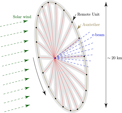
The E-sail has potentially revolutionary performance level in comparison to other propulsion systems [4]. The tether weighs only 10 grams per kilometre and produces a thrust of mN/km at 1 au distance. The E-sail thrust scales as proportional to where is the solar distance. The reason is that while the solar wind dynamic pressure decays as , the plasma Debye length (by which the electric field penetration distance and hence the virtual sail size scales) varies as , thus giving an overall dependence for the thrust. For example, hundred 20 km long tethers would weigh 20 kg and they would produce 1 N thrust at 1 au which gives a 30 km/s velocity change pear year for a 1000 kg spacecraft.
E-sail thrust magnitude can be easily controlled between zero and a maximum value by changing the voltage of the tethers. The tether voltage is maintained by continuously operating an electron gun which pumps out negative charge from the system, hence tether voltage can be actuated easily by changing the current and voltage of the electron gun beam. The power consumption of the electron gun is moderate (700 W nominally at 1 au for large 1 N sail) and it scales as , i.e. in the same way as the illumination power of solar panels. The power consumption stems from the electron current gathered from the surrounding solar wind plasma by the positively charged tethers which can be estimated by so-called orbital motion limited (OML) cylindrical Langmuir probe theory [2],
| (1) |
Here is the electron charge, is the solar wind plasma density, is the tether bias voltage, is electron mass, m is the base wire radius of the micrometeoroid-resistant tether, which is assumed to have four wires in Eq. (1) with parallel wire radius m and loop wire radius m.
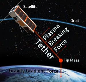
Later it was found [5, 6] that Coulomb drag propulsion can also be used for satellite deorbiting in low Earth orbit (LEO). Contrary to the solar wind, in LEO it seems more attractive to use negative tether polarity because it needs less power than a positive polarity one and because the balancing ion emitter can in LEO conditions often be implemented simply by the satellite’s conducting surface. The LEO application is called the plasma brake (Fig. 2). According to simulations, a 5 km long negatively charged plasma brake tether weighing 0.055 kg could produce 0.43 mN braking force which is enough to reduce the orbital altitude of a 260 kg object by 100 km per year [7].
Part of the material in this paper is taken from the Space Propulsion 2014 proceedings paper [9].
hysics of Coulomb drag
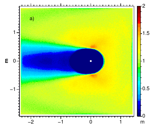
When plasma streams past a charged thin tether, the tether’s electric field penetrates some distance into the plasma and deflects the charged particles of the stream. Because electrons are lightweight, the momentum flux carried by them is negligible so it is enough to consider the deflection of ions. Both positively and negatively biased tethers cause ion deflection and hence Coulomb drag. A positive tether deflects positively charged ions by repelling them (Fig. 3). A negative tether deflects ions by attracting them so that their paths cross behind the tether (Fig. 4).
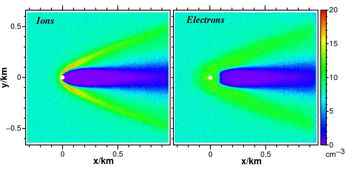
2.1 Positively biased tether
A positively biased tether repels stream ions and attracts electrons. When the potential is turned on, a population of trapped electrons gets formed [2]. In most of the literature concerning biased tethers, it is implicitly or explicitly assumed that trapped electrons are not present in the asymptotic state. In a multi-tether starfish-shaped E-sail geometry (Fig. 1), trapped electron orbits are chaotised whenever the electron visits the central “hub” which is the spacecraft, and chaotised electrons have a small nonzero probability of getting injected into an orbit which takes them to collision course with a tether wire so that trapped electrons are removed by this mechanism in few minute timescale in nominal 1 au solar wind [11]. It might be that other processes such as plasma waves occur in nature which speed up the process. By PIC simulations alone it is not easy to predict how many trapped electrons are present in the final state, although the question was recently analysed also using a novel, indirect approach [12].
The E-sail thrust per tether length is given by
| (2) |
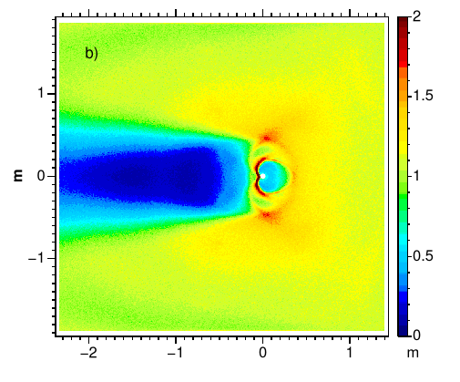
where is a numerical coefficient of order unity, is the dynamic pressure of the plasma flow and is the radius of the electron sheath (the penetration distance of the electric field into the plasma). The quantity can be inferred from recent laboratory measurements of Siguier et al. [13] where Ar+ plasma (ion mass u) of density m-3 accelerated to 20 eV bulk flow energy (hence speed km/s) was used and let to interact with mm radius metal tether biased to V and 400 V in two experiments. At V the sheath radius as visually determined from their Figure 7 is cm and at 400 V it is cm (from their Figure 8). For estimating the corresponding , let us assume in the above formula [Eq. (2)]. This corresponds to assuming that ions incident on the sheath are on average deflected by 90∘ (notice that the size of the virtual obstacle made by the sheath is twice its radius). We think that this is a reasonable first estimate since ions arriving head-on towards the tether are reflected backwards while ions arriving near the boundaries of the sheath are probably deflected less than 90∘. In their experiment Pa so Eq. 2 gives nN/m and nN/m for equal to 100 V and 400 V, respectively.
Let us compare these experimentally inferred values with theoretical estimates. A simple theoretical estimate for the sheath radius is the effective Debye length
| (3) |
where is the stream ion bulk flow energy. The expression (3) for the effective Debye length is obtained from the usual formula for ordinary electron Debye length by replacing the electron temperature by the tether voltage. We also subtract the bulk energy term to model the fact that if the tether voltage is lower than the bulk energy, it can no longer reflect back or stop ions but only weakly deflects them even if they arrive with zero boost parameter; the subtraction of however has only modest impact to our results. If one takes to be equal to in Eq. (2), one obtains equal to 420 nN/m and 910 nN/m for equal to 100 V and 400 V, respectively.
Theoretical E-sail thrust formulas of [4] contain the average electron density inside the sheath as a free parameter, the choice giving the largest E-sail thrust. Assuming and applying the formulas for the experimental parameters of Siguier et al. [13], one obtains 220 nN/m and 740 nN/m thrust per length for equal to 100 V and 400 V, respectively.
We summarise the experimental and theoretical results in Table 1.
2.2 Negatively biased tether
In the negative polarity case, electrons are simply repelled by the tether (Fig. 4) and hence the physics of electrons is simple. We believe that PIC simulations therefore have a good chance of predicting the thrust correctly in the negative polarity case. Using a new supercomputer, a comprehensive set of negative polarity PIC simulations for LEO-like parameters was recently conducted [7] and it was found that the following formula gives a good fit to the PIC simulations:
| (4) |
Here is the ionospheric plasma ram flow speed relative to spacecraft (assumed to be perpendicular to the tether or else denotes only the perpendicular component), is the flow dynamic pressure, is the ion mass (typically the plasma is singly ionised atomic oxygen so that u),
| (5) |
is the tether’s effective electric radius (Appendix A of [2]), is the effective Debye length and is the bulk ion flow energy in voltage units. The effective electric radius is approximately given by mm, where is the tether wire radius, typically 12.5-25 m, and is the tether width, typically 2 cm (a rough value of is sufficient to know because enters into Eq. (4) only logarithmically).
Thus, although experimental confirmation is needed, there is good reason to believe that Eq. 4 describes LEO plasma brake thrust well. The only exception is that if the geomagnetic field is predominantly oriented along the tether, the interaction becomes turbulent and the thrust is moderately reduced [7]. The reduction grows with increasing voltage: it is 17% at V bias voltage and 27% at V. For a vertical gravity-stabilised plasma brake tether in polar orbit, efficiency reduction with respect to Eq. (4) is thus expected at high latitudes.
We emphasise that Eq. (4) has thus far only been verified with simulations in LEO plasma environment conditions. If negative polarity Coulomb drag devices would become relevant in the future also in other plasma conditions, the applicability of Eq. (4) should be considered carefully on a case by case basis.
STCube-1 experiment
ESTCube-1 was a 1-U Estonian cubesat which flew in 2013-2015 [14]. ESTCube-1 carried a preliminary 10 m version of our tether experiment [15]. The experiment did not work because the tether reel failed to rotate. A reason was identified after the launch in ground testing: a gold-plated slipring was pressed by a steel spring contactor and during launch vibration, the contactor carved a small hole into the slipring which was enough to prevent the piezoelectric motor from turning the reel. Although the error was in our tether payload, it was a “shallow” problem whose reason was insufficient vibration testing before launch, which in turn was due to 5-month accelerated schedule of the satellite in a late phase, due to sudden emergence of a free launch opportunity and the satellite team’s decision to accept it. The error was thus not directly related to any deeper aspects of Coulomb drag tether technology.
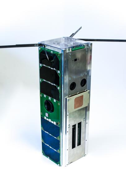
alto-1 satellite
Aalto-1 [8] (Fig. 5) is a Finnish 3-U, 4 kg cubesat which will be launched in polar LEO in May 2016 onboard SpaceX Falcon-9 rocket. Like ESTCube-1, the Aalto-1 cubesat is built by university students while the payloads are made by research groups. Aalto-1 carries three payloads, AASI imaging Fabry-Perot spectrometer (hyperspectral camera) by VTT, a compact radiation monitor (RADMON) by the University of Turku and our Coulomb drag tether experiment.
alto-1 tether experiment
The tether experiment of Aalto-1 is a debugged version of the ESTCube-1 experiment: known problems have been fixed, testing was more complete than in case of ESTCube-1, and more diagnostics were added so that if something goes wrong, we will be able to know more precisely what it was.
The length of the tether in Aalto-1 is 100 m i.e. ten times longer than in ESTCube-1. The tether is made of four 25 and 50 micrometre diameter aluminium wires that are ultrasonically bonded together every few centimetre intervals [16, 17]. The tether can be charged by an onboard voltage source up to one kilovolt positive or negative with respect to surrounding plasma. The negative polarity Coulomb drag experiment of Aalto-1, in particular, is expected to yield a practical demonstration of plasma braking by significantly lowering the orbit of the satellite or even deorbiting it entirely.
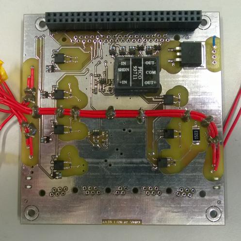
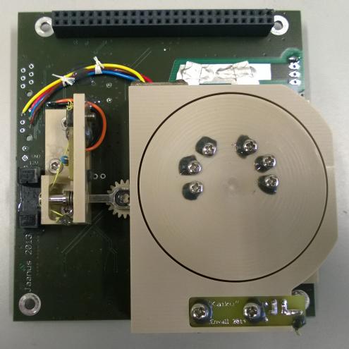
Figure 6 shows the high-voltage (HV) and motor cards of the Aalto-1 tether payload. The motor card also hosts the tether reel. The lateral size of both cards is about cm (a standard cubesat circuit board) and together they take 50.5 mm of vertical space so that both cards together take 0.5U of volume. The motor card weighs 148 g and the HV card weighs 114 g so that together they weigh 262 g.
When the tether experiment is started, the satellite is spun up using magnetic coils, the 1.2 g endmass and reel locks are released and the motor is commanded to turn the reel. The tether then starts to deploy and the centrifugal pull of the endmass keeps it under proper tension. When deployment proceeds, the tether tension first increases almost linearly with tether length. When the moment of inertia of the deployed part of the tether has become comparable to the satellite’s moment of inertia, the tension reaches a maximum at m tether length and then starts to decrease again because the satellite’s rotation slows down due to angular momentum conservation.
We deploy first about 10 m of the tether and then start positive tether polarity experiments by operating the satellite’s cold cathode electron gun [18]. The reason for starting positive mode experiments with relatively short tether is to ensure that the current produced by the gun is sufficient to balance the electron current gathered by the positively biased tether from the plasma. Otherwise there would be a risk that the tether voltage would drop an unknown amount below the electron gun beam voltage so that the tether voltage would become unknown.
The tether spins in equatorial plane and we perform the Coulomb drag experiment primarily over high latitudes so that the plasma ram flow is in the plane of the tether. We measure the Coulomb drag thrust in the following indirect way. We keep the tether voltage on whenever the tether is moving downstream with respect to plasma ram flow and keep it off when it moves upstream. In this way the Coulomb drag that is exerted on the tether accelerates the tether’s and the satellite’s spin during each spin period. Because the effect accumulates over successive spins, it relatively quickly should yield a change in the satellite’s spinrate which is large enough to be easily measurable by the attitude control system and also by simple and robust methods such as looking at the periodicity of the sun sensor signals or power produced by a particular solar panel. The purpose of positive mode experiments is to determine the positive mode thrust as a function of plasma density, which can be estimated based on orbital location and geophysical conditions from ionospheric models such as International Reference Ionosphere (IRI) [19].
After successful positive mode tests at m length, a similar series of negative mode experiments is also carried out. The negative mode does not need the electron gun, but only a HV source which forces the tether negative with respect the satellite frame. Conducting parts of the satellite surface then go weakly positive until they gather enough thermal electron flux from the plasma to balance the negative tether’s gathered plasma ion current. As a result, the tether’s negative voltage will be very nearly the same as the voltage given by the source so that the tether will be in a known negative voltage.
After successful experiments at m length, one of the Coulomb drag effects is used to increase the spinrate so that tether deployment can continue beyond 10 m while keeping a tether tension which is large enough to keep it straight and to overcome any Coulomb drag effect by a large margin. The process is continued until all 100 m have been deployed, likely interleaving deployment phases and spin acceleration phases 2-3 times. At the end, the voltage is left on the tether all the time in negative mode so that the spinrate is no longer modified, but the satellite’s centre of mass experiences the drag and the orbit is lowered. If the experiment can run for months in this mode, clear lowering in satellite’s orbital altitude should be observable, of order 5-10 km per month. In the very best case, if the satellite stays alive for a long enough time, it’s possible that full deorbiting will eventually result due to the plasma brake effect followed by engaging the atmospheric drag at lower altitudes.
xpected plasma brake thrust
Recall from section 2.2 that for LEO parameters, Eq. 4 is a good fit to PIC simulations (except for modest thrust reduction due to turbulence when the dominant component of the geomagnetic field is along the tether) which in turn are expectedly good models of reality in case of negative tether voltage.
One noteworthy fact is that LEO plasma brake thrust according to Eq. 4 is proportional (through linear dependence on ) to the ion mass . Thus, plasma brake thrust is 16 times larger in pure oxygen O∘ plasma than in pure proton plasma.
For example, at kV, m-3, km/s and u, Eq. 4 gives 85 nN/m thrust. In the negative bias case, usable tether voltage is limited by onset of electron field emission. We think that above 1-2 kV, field emission might start to become an issue.
| Altitude | MLT 12-00 | MLT 06-18 | Average |
|---|---|---|---|
| 700 km | 47/157 | 42/140 | 44/149 |
| 800 km | 33/117 | 30/108 | 32/112 |
| 900 km | 25/88 | 22/84 | 23/86 |
Table 2 gives plasma brake thrust based on Eq. 4, assuming kV, km/s and using plasma density and chemical composition taken from the IRI-2012 ionospheric model [19], for noon-midnight (mean local time MLT 12-00) and dawn-dusk (MLT 06-18) polar orbits and for solar minimum and maximum ionospheric conditions. We see from Table 2 that the dependence on solar cycle is relatively significant, about factor 3.5. The solar cycle dependence is due to increased plasma density and increased oxygen abundance during solar maximum conditions. There is obviously also an altitude dependence. Below 700 km the thrust would continue to increase until km, provided that the hardware is designed to take advantage of it. The dependence on MLT is weak.
As a numerical example, consider a 10 km long plasma brake tether which starts bringing down a debris object of 200 kg mass from 800 km circular orbit in an MLT which is average between dawn-dusk and noon-midnight. The required from 800 km to 700 km is 53.5 m/s and from 700 km to 400 km 165 m/s. During solar minimum, deorbiting from 800 km to 700 km takes 0.88 years and the rest from 700 km to 400 km (assuming the same thrust as at 700 km) takes 2.4 years, thus altogether 3.25 years. During solar maximum the 800700 km deorbiting takes 0.25 years and 700400 km 0.7 years, thus altogether 0.96 years. These estimates are conservative since in reality plasma density and oxygen concentration and hence plasma brake thrust continue to grow below 700 km.
iscussion and conclusions
Based on plasma simulations and an indirect laboratory result, there is good reason to think that the magnitude of tether Coulomb drag is in very useful range at least for (1) positive tether in solar wind (E-sail) and (2) negative tether in LEO (plasma brake).
Coulomb drag propulsion in both positive and negative mode will soon be attempted to be measured by Aalto-1 satellite. Aalto-1 is a 3-U cubesat to be launched in May 2016 in polar LEO. Ideally we will get a measurement of positive and negative mode Coulomb drag as function of plasma density, tether length and voltage. The results can then be compared with earlier simulation predictions. We should also be able to observe measurable lowering of the satellite orbit using the negative mode at 100 m tether length. In the very best case, if the satellite and the experiment stay alive long enough, we could even observe reentry into atmosphere.
Acknowledgements. This research was partially financed within the European Community’s Seventh Framework Programme ([FP7/2007-2013]) under grant agreement number 262733, the Academy of Finland grant 250591 and European Space Agency grant 4000115856/15/NL/PS/gp.
References
- [1] Janhunen, P., Electric sail for spacecraft propulsion, J. Prop. Power, 20, 763–764, 2004.
- [2] Janhunen, P. and A. Sandroos, Simulation study of solar wind push on a charged wire: basis of solar wind electric sail propulsion, Ann. Geophys., 25, 755–767, 2007.
- [3] Janhunen, P. and P. Toivanen, TI tether rig for solving secular spinrate change problem of electric sail, http://arxiv.org/abs/1603.05563, Acta Astronaut., submitted, 2016.
- [4] Janhunen, P., P.K. Toivanen, J. Polkko, S. Merikallio, P. Salminen, E. Haeggström, H. Seppänen, R. Kurppa, J. Ukkonen, S. Kiprich, G. Thornell, H. Kratz, L. Richter, O. Krömer, R. Rosta, M. Noorma, J. Envall, S. Lätt, G. Mengali, A.A. Quarta, H. Koivisto, O. Tarvainen, T. Kalvas, J. Kauppinen, A. Nuottajärvi and A. Obraztsov, Electric solar wind sail: Towards test missions, Rev. Sci. Instrum., 81, 111301, 2010.
- [5] Janhunen, P., On the feasibility of a negative polarity electric sail, Ann. Geophys., 27, 1439–1447, 2009.
- [6] Janhunen, P., Electrostatic plasma brake for deorbiting a satellite, J. Prop. Power, 26, 370–372, 2010.
- [7] Janhunen, P., Simulation study of the plasma brake effect, Ann. Geophys., 32, 1207–1216, 2014.
- [8] Kestilä, A., T. Tikka, P. Peitso, J. Rantanen, A. Näsilä, K. Nordling, H. Saari, R. Vainio, P. Janhunen, J. Praks and M. Hallikainen, Aalto-1 nanosatellite – technical description and mission objectives. Geosci. Instrum. Method. Data Syst., 2, 121–130, 2013.
- [9] Janhunen, P., Coulomb drag devices: electric solar wind sail propulsion and ionospheric deorbiting, Space Propulsion 2014, Köln, Germany, May 19-22, 2014 (http://arxiv.org/abs/1404.7430).
- [10] Janhunen, P., PIC simulation of Electric Sail with explicit trapped electron modelling, ASTRONUM-2011, Valencia, Spain, June 13–17, ASP Conf. Ser., 459, 271–276, 2012 (http://www.electric-sailing.fi/papers/ASTRONUM2011.pdf).
- [11] Janhunen, P., Increased electric sail thrust through removal of trapped shielding electrons by orbit chaotisation due to spacecraft body, Ann. Geophys., 27, 3089–3100, 2009.
- [12] Janhunen, P., Boltzmann electron PIC simulation of the E-sail effect, Ann. Geophys., 33, 1507–1512, 2015.
- [13] Siguier, J.-M., P. Sarrailh, J.-F. Roussel, V. Inguimbert, G. Murat and J. SanMartin, Drifting plasma collection by a positive biased tether wire in LEO-like plasma conditions: current measurement and plasma diagnostic, IEEE Trans. Plasma Sci., 41, 3380–3386, 2013.
- [14] Lätt, S., A. Slavinskis, E. Ilbis, U. Kvell, K. Voormansik, E. Kulu, ESTCube-1 nanosatellite for electric solar wind sail in-orbit technology demonstration, Proc. Estonian Acad. Sci., 63(2S), 200–209, 2014.
- [15] Envall, J., P. Janhunen, P. Toivanen, M. Pajusalu, E. Ilbis, J. Kalde, M. Averin, H. Kuuste, K. Laizans, V. Allik, T. Rauhala, H. Seppänen, S. Kiprich, J. Ukkonen, E. Haeggström, T. Kalvas, O. Tarvainen, J. Kauppinen, A. Nuottajärvi and H. Koivisto, E-sail test payload of ESTCube-1 nanosatellite, Proc. Estonian Acad. Sci.,, 63, 210–221, 2014.
- [16] Seppänen, H., S. Kiprich, R. Kurppa, P. Janhunen and E. Haeggström, Wire-to-wire bonding of um-diameter aluminum wires for the Electric Solar Wind Sail, Microelectronic Engineering, 88, 3267–3269, 2011.
- [17] Seppänen, H., T. Rauhala, S. Kiprich, J. Ukkonen, M. Simonsson, R. Kurppa, P. Janhunen and E. Haeggström, One kilometer (1 km) electric solar wind sail tether produced automatically, Rev. Sci. Instrum., 84, 095102, 2013.
- [18] Kleshch, V.I., E.A. Smolnikova, A.S. Orekhov, T. Kalvas, O. Tarvainen, J. Kauppinen, A. Nuottajärvi, H. Koivisto, P. Janhunen and A.N. Obraztsov, Nano-graphite cold cathodes for electric solar wind sail, Carbon, 81, 132–136, 2015.
- [19] Bilitza, D., L.-A. McKinnell, B. Reinisch and T. Fuller-Rowell, The International Reference Ionosphere (IRI) today and in the future, J. Geodesy, 85, 909–920, 2011.