Magnon Hall effect in AB-stacked bilayer honeycomb quantum magnets
Abstract
Motivated by the fact that many bilayer quantum magnets occur in nature, we generalize the study of thermal Hall transports of spin excitations to bilayer magnetic systems. It is shown that bilayer magnetic systems can be coupled either ferromagnetically or antiferromagnetically. We study both scenarios on the honeycomb lattice and show that the system realizes topologically nontrivial magnon bands induced by alternating next-nearest-neighbour Dzyaloshinsky-Moriya interaction (DMI). As a result, the bilayer system realizes both magnon Hall effect and magnon spin Nernst effect. We show that antiferromagnetically coupled layers differ from ferromagnetically coupled layers by a sign change in the conductivities as the magnetic field is reversed. Furthermore, Chern number protected magnon edge states are observed and propagate in the same direction on the top and bottom layers in ferromagnetically coupled layers, whereas the magnon edge states propagate in opposite directions for antiferromagnetically coupled layers.
pacs:
66.70.-f, 75.30.-m, 75.10.Jm, 05.30.JpI Introduction
Magnons are the collective excitations of ordered quantum magnets such as ferromagnets or antiferromagnets. In quantum magnetic systems that lack inversion symmetry, the DMI (spin-orbit coupling)dm is present and leads to chiral magnons with nontrivial topological properties alex0 ; alex1 ; zhh ; shin ; shin1 ; alex1a similar to electronic systems yu6 ; yu7 ; fdm . As magnons are uncharged (neutral) quasiparticles, they do not experience a magnetic field in the Lorentz force as in the electronic version of Hall effect. Instead, they exhibit a thermal version of Hall effect in which a temperature gradient transports a heat current zhh ; alex1 ; alex0 ; alex7 ; alex4 ; alex44 . The DMI generates a nonzero Berry curvature given by alex2 , where is a DMI dependent vector potential. The Berry curvature acts as an effective magnetic field by altering the propagation of magnons in the system, thus leads to thermal Hall effect dubbed magnon Hall effect alex1 ; alex0 , as well as magnon spin Nernst effect alex7 . These two phenomena are characterized by two conductivities — transverse thermal conductivity and transverse spin Nernst conductivity . They are both directly related to the Berry curvature of the magnon bulk bands reminiscent of Hall conductivity in electronic systems thou . However, in contrast to electronic systems, there is no completely filled bands in bosonic systems, so each magnon band contributes a term to and , and the Chern number of the system simply leads to protected chiral magnon edge states.
The first experimental realization of magnon Hall effect has been reported in three-dimensional (3D) pyrochlore ferromagnetic insulators Lu2V2O7, Ho2V2O7, and In2Mn2O7 alex1 ; alex1a . Quite recently, magnon Hall effect has been observed in 2D kagome magnet Cu(1-3, bdc) alex6 ; alex6a . Both theory and experiment show that the topology of the system leads to a sign change in as a function of temperature or magnetic field on the kagome lattice alex4 ; alex6 ; alex6a and a sign change in as the magnetic field is reversed on the pyrochlore lattice alex1 ; alex1a . These experimental observations have propelled a possibility of numerous experimentally accessible 2D ferromagnets in different lattices that exhibit nontrivial topological spin excitations. In this regard, magnon Hall transports have been proposed on a single-layer Lieb ferromagnet xc with three magnon bulk bands, in which a sign change was also observed in . The honeycomb ferromagnet is special as it applies to experimentally accessible graphene sheet yu6 ; yu7 ; cas . It also forms an example of nontrivial topological energy bands in electronic systems fdm . In the context of magnon Hall transports, the author has recently shown that nontrivial magnon bands and magnon Hall effect could be accessible in a single-layer honeycomb quantum ferromagnets, in which a DMI is allowed by the alternating triangular plaquettes of the next-nearest-neighbour sites sol ; sol1 . For the honeycomb lattice, shows no sign change for all parameters of the system sol1 . Recent study has shown that the proposed honeycomb ferromagnetic system also exhibits spin Nernst effect kkim . It has been previously shown that an interfacial contact between two magnon insulators can lead to nontrivial transport properties on the kagome ferromagnet mook .
Motivated by these theoretical and experimental realizations of thermal Hall effects of spin excitations and the experimental realizations of bilayer honeycomb-lattice quantum magnetic compounds such as Na3Cu2SbO6 aat1 , -Cu2V2O7 aat , and A2IrO3 (A= Na, Li) aat0 ; aat00 , we study thermal Hall transports of magnons in bilayer honeycomb magnetic systems. Generalization to other bilayer systems is straightforward. We show that two layers of magnon insulators with the same DMI can be coupled either ferromagnetically or antiferromagnetically. In the former, we show that the presence of an alternating next-nearest-neighbour DMI generates Berry curvatures and dissipationless magnon edge states, which propagate in the same direction on the top and the bottom layers of the bilayer system. We compute the thermal Hall and spin Nernst conductivities. For the latter case, the spins on the upper/lower layer point in opposite direction to those on the lower/upper layer, hence the interlayer couplings become antiferromagnetic. In this case, we show that magnon edge states propagate in opposite directions. As a result, thermal Hall and spin Nernst conductivities also show a change sign as the magnetic field is reversed. This result is interesting because it is what is seen experimentally in many ferromagnetic insulators alex1 ; alex1a . As thermal Hall transports of magnons await experimental observation on the honeycomb lattice, our results open new avenue to search for 2D and 3D bilayer systems with nonzero thermal Hall transports.
II Bilayer magnon insulator
Bilayer magnon insulators consist of two single-layer of magnon insulators coupled either ferromagnetically or antiferromagnetically as shown in Fig. 1. The Hamiltonian is governed by
| (1) |
where, represents the single-layer Hamiltonians for the top and bottom layers respectively, represents the DMI interactions on both layers, is the external magnetic field on each layer, and is the interlayer couplings between them. For the honeycomb lattice, they are given by
| (2) | |||
| (3) | |||
| (4) | |||
| (5) |

where is the spin moment at site , is a nearest-neighbour (NN) ferromagnetic interaction on each layer, and is the magnitude of the DMI which is allowed by the next-nearest-neighbour (NNN) triangular plaquettes on the honeycomb lattice, where represents hopping from left to right and vice versa on the NNN sites. The Zeeman magnetic field is in units of . The interlayer NN interactions denotes all the possible interlayer couplings depicted in Fig. 1.
III Magnon bands
In this section, we present the band structure of the bilayer honeycomb magnetic system using the linearized HP boson representation of the spin operators HP , which is valid at low-temperature when few magnons are thermally excited. In fact, this formalism has been employed frequently in the study of thermal Hall transports of magnons in ferromagnetic systems zhh ; alex0 ; alex1 ; alex2 ; alex4 . It is also supported in recent experimental realizations alex6 ; alex6a ; alex1 .
III.1 Ferromagnetically coupled layers
We first start with ferromagnetically coupled layers, . Using the linearized HP transformation, the magnon tight binding hopping model is given by
| (6) | ||||
| (7) |
where , , and is coordination number of the lattice. The interlayer coupling is . Similar to AB-stacked bilayer graphenemcc ; mcc1 ; mcc2 ; mcc3 there are three kinds of interlayer couplings as shown in Fig. 1. We identify the bottom layer with two sublattices labeled and , and the top layer with and . The exchange interaction couples and , couples and , and couples and , and . In Fourier space the momentum space Hamiltonian is given by with the basis , where the Bogoliubov Hamiltonian is given by

| (10) |
where
| (13) |
| (16) |
| (19) |
where , and . The lattice factor is and the mass is , with . Notice that the shifting parameters and are the major differences between the bilayer magnon insulator and that of spin orbit coupled AB-stacked bilayer graphene mak55 . As a result for , the eigenvalues of the bilayer magnon insulator yields
| (20) | |||
| (21) |
At the Dirac points , and . The lowest band has a Goldstone mode at when . The evolution of the magnon bands are shown in Fig. 2. For there are three gapless bands at as opposed to AB-stacked bilayer graphene mcc ; mcc1 ; mcc2 ; mcc3 .
III.2 Antiferromagnetically coupled layers
The magnon insulator can also be coupled antiferromagnetically. In this case, the spins on the upper layer are designed to point in opposite direction to those on the lower layer, hence the interlayer couplings become antiferromagnetic with . To capture the correct magnetic excitations, we perform a -rotation about the -axis on the upper layer, that is , , (see Appendix A). This rotation does not change the ferromagnetic nature of the upper layer , but it rotates the spins along the new -axis and changes the sign of upper-layer out-of-plane DM interaction, and the upper-layer external magnetic field . In the HP bosonic representation, the interlayer coupling has the form
| (22) |
Introducing the Nambu operators , the momentum space of the total Hamiltonian can be written as where is a ( is the number of sublattices) matrix given by
| (25) |
The matrices and are given by
| (26) |
| (27) |
where and with , , , . Also with . Due to the mass term , but .
The Hamiltonian is hermitian but not diagonal. It can be diagonalized by the generalized Bogoliubov transformation , where is a matrix and with being the quasiparticle operators. The matrix satisfies the relations,
| (28) |

with , and is the diagonal matrix of the quasiparticle energy eigenvalues. Using the fact that , then Eq. 28 is equivalent to saying that we need to diagonalize a non-hermitian Hamiltonian
| (31) |
whose eigenvalues are given by and the columns of are the corresponding eigenvectors. We could not find an analytical expression in this case. Figure 3 shows the positive energy bands. At the Dirac points , the eigenvalues can be found analytically. They are given by , , . A careful calculation also shows that antiferromagnetically coupled bilayer ferromagnets behaves very similar to antiferromagnetically coupled bilayer antiferromagnets with Néel states, i.e., . For the most part of this paper, we will focus on the special limit for simplicity. In many cases of physical interest, the magnetic field can induce canting of spins in antiferromagnetic systems. This scenario is analyzed in Appendix B.
IV Topological magnon transports
IV.1 Magnon edge states
We now study the main purpose of this paper — thermal Hall transports of magnons. As the DMI plays the same role as spin-orbit coupling mak55 , topological effects in magnon insulators stem from nontrivial properties of the chirality-induced Berry curvatures. This directly implies the propagation of magnon edge states on the edges of each layer. Having diagonalized the Hamiltonians, the Berry curvature of the magnon bulk bands can be written as
| (32) |
where defines the velocity operators with . The columns of are the eigenvectors, and labels the bands. For antiferromagnetically coupled layers, and is paraunitary. In the antiferromagnetic case the Berry curvature can be written alternatively as
| (33) |
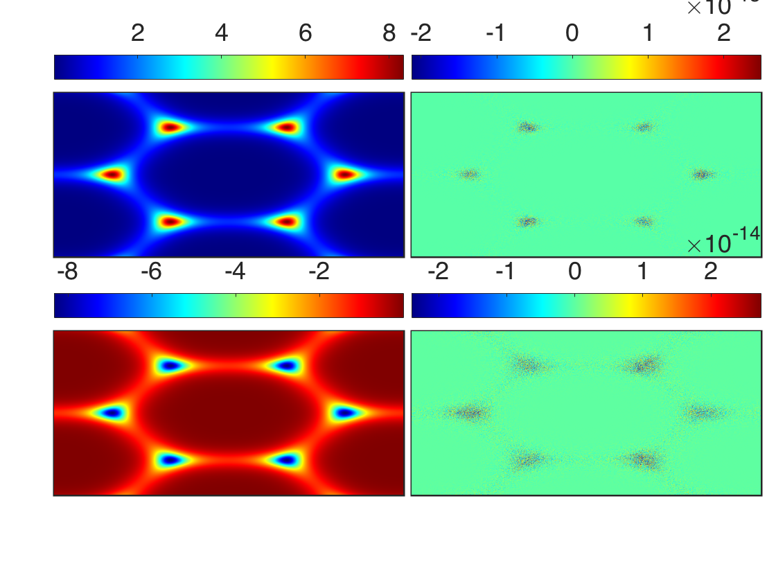
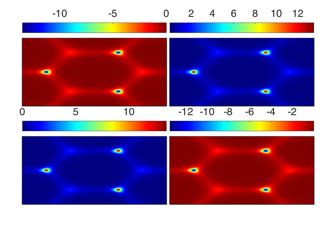
which can be used for systems with explicit analytical form of . The Berry curvature for ferromagneticcally coupled layers is shown in Fig. 4(a) and antiferromagneticcally coupled layers in Fig. 4(b). In the former, only the Berry curvatures corresponding to the bands are peaked at the Dirac points. This is due to the biased nature of the system. On the other hands, the latter Berry curvatures for each band is suppressed at three corners of the Brillouin zone [see the corresponding bands in Fig. 3(b)]. Although magnon Hall transports are induced by the Berry curvatures, the Chern numbers can still be defined for bosonic systems as the integration of the Berry curvature over the first Brillouin zone given by,
| (34) |
For ferromagnetically coupled layers, the Chern number of the bands and are given by and antiferromagnetically coupled layers, we find . We see that the sum of the Chern numbers is zero as can also be seen from the Berry curvatures. Similar to AB-stacked bilayer graphene mak55 , the Chern numbers are double that of single layer sol . This implies that the edge states are also double that of single layer [Fig. 5(a) ] as depicted in Figs. 5(a) and and 5(b) . We also observe magnon edge states at zero DMI [Figs. 5(a) and 5(b) ], which is not protected by any Chern number similar to AB-stacked bilayer graphene castt . The magnon edge states for ferromagnetically and antiferromagnetically coupled layers differ by the direction of propagation as shown schematically in Figs. 6(a) and 6(b).


IV.2 Magnon Hall and Spin Nernst effects
Theoretically, thermal Hall effect of magnons is manifested due to the nontrivial topology of the magnon band structures induced by the DMI. The non-vanishing Berry curvatures induce an effective magnetic field in the system, upon the application of a longitudinal temperature gradient . Figure 7(a) shows the schematic representation of magnon Hall effect, in which a longitudinal temperature gradient induces a transverse heat current . The propagation of magnon in the bilayer system is deflected by the DMI on the top and bottom layers. This leads to thermal Hall effect alex0 characterized by the transverse thermal Hall conductivity given by alex2 ; shin1 where is the volume of the system, is the Boltzmann constant, is the temperature, is the Bose function, and is a dilogarithm.


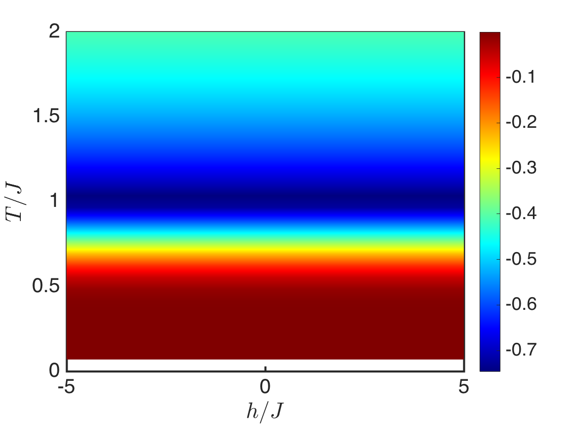

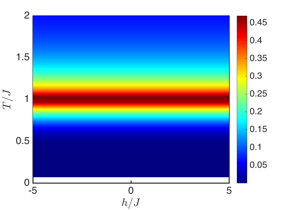
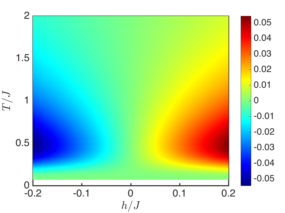
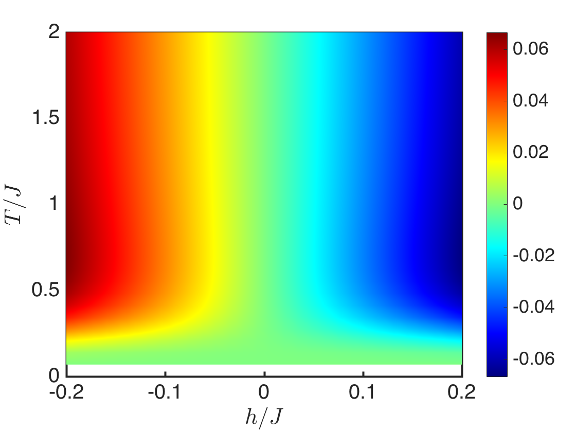
In what follows, we focus on the simplified model with nonzero . The trend of the thermal conductivity is shown in Fig. 8(a) for several values of and fixed . At , and decreases exponentially for large temperature approaching a constant value for very large temperature but never changes sign. Increasing the DMI, , decreases . The contour plot of in Fig. 8(b) shows no sign change by reversing the magnetic field. As previously mentioned, magnon edge state propagation also carries a transverse spin current which leads to spin Nernst effect depicted in Fig. 7(b). It can be understood as two copies of magnon Hall effects with opposite spins. It is characterized by a conductivity given by alex7 where . Due to the Berry curvature, has a similar feature as except that it is now positive as shown in Fig. 8(c). The spin Nernst conductivity also vanishes at zero temperature as there are no thermal excitations but the DMI, increases . We see that does not show any sign change for all parameters considered as shown in Fig. 8(d).
For antiferromagnetically coupled layers, the propagation of magnons are deflected in opposite directions by opposite signs of DMI on each layer (see Eq. 25). In addition, the Berry curvature changes sign as the magnetic field is reversed (not shown). Hence, the topology of the system is different from ferromagnetically coupled layers. This is manifested explicitly in the conductivities as shown in Figs. 9(a) and 9(b). The sign change in and as the magnetic field is reversed is the manifestation of the band topology of the system for antiferromagnetically coupled layers. A different sign change has been studied on the kagome lattice. In this case, Ref. [alex44, ] explains the sign change in as a consequence of the sign change in Berry curvature of the highest band and Ref. [alex4, ] argues that the sign change in is a consequence of the propagation of the magnon edge states, however, with a NNN interaction. The origin of the sign change on the kagome ferromagnets is still not well-understood theoretically. In the present case with antiferromagnetic coupling, reversing the magnetic field flips the spin moments on both layers and thus changes the sign of the spin and bosonic operators in HP transformation (see Appendix A). This has an important consequence on the sign of the DMI on each layer and affects the signs of the conductivities.
V Conclusion
We have presented a detail study of magnon Hall transports in AB-stacked bilayer honeycomb magnon insulators. We show that the interlayer couplings between two ferromagnetic magnon insulators can be treated ferromagnetically or antiferromagnetically. For ferromagnetic coupling, we present explicit calculation based on magnon tight binding model obtained from linearized HP transformation. We show that the system behaves similarly to AB-stacked bilayer graphene and possesses nontrivial topological magnon bulk bands and Berry curvatures. However, for magnon insulators the propagation of edge states give rise to thermal Hall effect and spin Nernst effect. We show that for ferromagnetically coupled layers, the conductivities characterizing these effects are very similar to single-layer honeycomb magnon insulator with no sign change. For antiferromagnetically coupled layers, we show that the topological nature of the magnon bands is different. Magnon edge states propagate in opposite directions and the conductivities of thermal Hall response show a sign change as the magnetic field is reversed.
To the best of our knowledge, thermal Hall effect of magnons has been observed experimentally only in ferromagnetic insulators without inversion symmetry. The Lieb and honeycomb lattices still await experimental observation. In these systems, spin-orbit coupling (DMI) can be induced in many different ways. For the honeycomb lattice, it is also possible to utilize ultracold bosonic atoms trapped in optical lattice at finite but low temperatures, since the bosonic tight binding model is reminiscent of tight binding model in electronic systems, where the Haldane model has been realized experimentally in optical fermionic lattice jott . The most important result of our study is that it opens new possibilities to search for bilayer magnon Hall transports in other lattices without inversion symmetry (such as the kagome and pyrochlore lattices), where nontrivial topological effects and magnon Hall effect have been realized experimentally. Our study also generalizes the study of magnon spintronics to bilayer systems. This model can also be studied using the spinon (Schwinger boson) representation. The Hamiltonian in this representation is an 8-band model, which can be regarded as two copies of Holstein-Primakoff Hamiltonians, one for each spin degree of freedom. The magnon bands and the associated magnon edge states are similar to that of gated AB-stacked bilayer graphene zhe . Both representations give similar results, however recent experimental results on the kagome magnet Cu(1-3, bdc) confirms that the Holstein-Primakoff boson representation gives a better estimate than the spinon representation alex6a ; alex6 .
Acknowledgments
Research at Perimeter Institute is supported by the Government of Canada through Industry Canada and by the Province of Ontario through the Ministry of Research and Innovation.
Appendix A Holstein-Primakoff representation
This appendix presents the well-known Holstein-Primakoff representation of spin operators. At low temperature, only few magnons are thermally excited. The linearized Holstein-Primakoff (HP) representation can be used to calculate the magnetic spin excitations. For the bilayer system, there are four sublattices, the HP representation for ferromagnetically coupled layers are given by
| (35) | |||
| (36) | |||
| (37) |
where label the sublattices. Similar representation holds for spins at site . When the magnetic field changes sign as , we imagine that the spins on both layers point in the direction of the field. The HP transformation is the same, except that we have to take , which accounts for spins pointing in the negative -direction. The magnon band structures are the same in both cases.
For antiferromagnetically coupled layers, the spins on the top layer are designed to point in opposite direction to those on the lower layer or vice versa, and the magnetic field is applied along the positive -direction. The interlayer coupling are replaced with . To capture the correct magnetic excitations, we write two different HP transformations for the top and bottom layers. For the bottom layer with up pointing spins we write
| (38) | |||
| (39) | |||
| (40) |
where label the sublattices on the bottom layer. For the top layer with down pointing spins we write
| (41) | |||
| (42) | |||
| (43) |
where label the sublattices on the top layer. Notice the signs of Eq. 41 and 42; see for example Ref. [ll, ]. This corresponds exactly to rotating the spins on the upper layer by about the direction to align them in the same direction as the bottom layer. When the magnetic field changes sign, we imagine that the spins on the top and bottom layers change direction as well, then Eqs. 38–40 apply to the top layer and Eqs. 41–43 apply to the bottom layer. In this case, the magnon band structures are very similar in both cases, but the topology of the system is different as shown above. At zero magnetic magnetic field, time-reversal symmetry is preserved and the band structure is doubly degenerate for as shown in Fig. 10 (a). Notice the linear dispersion near , which is an artifact of the low-energy excitations of antiferromagnetic quantum magnets.

Appendix B Field-induced canting in bilayer antiferromagnets
In many cases of physical interest, the magnetic field induces canting of spins in antiferromagnets. In this section, we consider this scenario in antiferromagnetically coupled layers governed by the Hamiltonian
| (44) |
where is a nearest-neighbour interaction, is a staggered DMI allowed by the next-nearest-neighbour triangular plaquettes on the honeycomb lattice, and . The Zeeman field is in units of and is the antiferromagnetic interlayer coupling.
For antiferromagnetically coupled ferromagnets considered above, . Because of antiferromagnetic coupling between the layers, the magnetic field can introduce canting on each layer. In this case, we rotate the coordinate axes such that the -axis coincides with the local direction of the classical polarization. The appropriate rotation on the two sublattices is given by
| (45) | |||
where applies to and respectively. This rotation does not affect the ferromagnetic term on each layer ().
In this system both the out-of-plane DMI () and the in-plane DMI () contribute to linear order in spin wave theory valid at low temperatures. For , the rotation in Eq. B rescales the DMI as . On the other hand, for , we have . However, the DMI does not contribute to the classical energy given by
| (46) |
where is the total number of sites. Minimizing the classical energy yields that canting angle , where . The term is invariant as mentioned above but the DMIs are given by
| (47) | |||
| (48) |
where and the primes have been dropped. The latter case changes sign on the top and bottom layers as shown in the text. Using the Holstein-Primakoff transformation
| (49) | |||
the interlayer coupling is given by
It is straight forward to compute the magnon bands. Interestingly, at the saturation field one recovers ferromagnetic coupled layers.
For fully antiferromagnetic coupled layers with , the appropriate rotation for the bottom layer is given by
| (50) | |||
For the top layer, we perform the rotation
| (51) | |||
The terms that contribute to linear spin wave theory are as follows,
| (52) | |||
| (53) | |||
| (54) | |||
| (55) | |||
| (56) |
The classical energy is given by
| (57) |
Minimization yields .
Appendix C Bilayer Bose-Hubbard model
In this appendix, we discuss bilayer honeycomb Bose-Hubbard model, recently studied numerically and shown to exhibit non-zero Berry curvature and bosonic edge states guo . The Hamiltonian is given by
| (58) | ||||
| (59) |
where, denotes NN hopping, is the chemical potential, and is a staggered on-site potential with for and for , is the occupation number which is either or . and are the bosonic creation and annihilation operators respectively. They obey the hard-core constraints for and . In the first approximation, only the vertical interlayer coupling contributes, while is the interlayer potential difference.
In this system, the DMI is zero (causes a sign problem in QMC) and nonzero Berry curvature is induced by the staggered onsite potential without a QMC sign problem guo . In order to study the bilayer Bose-Hubbard model analytically, it is expedient to map it to quantum spin Hamiltonian since the bilayer Bose-Hubbard model is a hard-core boson model. This is achieved via the transformation matq , . The resulting quantum spin Hamiltonian is given by
| (60) | ||||
| (61) |
where and .
For , this model reduces to single-layer Bose-Hubbard model on the honeycomb lattice, where can be considered as a staggered sublattice potential (magnetic field). There are several insulating phases uncovered by QMC phase diagram guo . We have recently complemented the QMC results using the present HP bosonic method sol2 . We uncovered the same quantum phase diagram and Berry curvatures seen in QMC guo . Thus, the topological properties of the single-layer Bose-Hubbard model uncovered by QMC correspond exactly to topological properties of magnon bulk bands of the corresponding spin- quantum magnets. This is due to the mapping between hard-core bosons and quantum spin systems. We also noticed that the Berry curvature of each band shows equal and opposite peaks at the corners of the Brillouin zone sol2 . This means that the integrated Berry curvature vanishes identically for each band, hence thermal Hall effect is not expected to manifest in this system without the DMI. For the bilayer model , the analysis follows a similar procedure. In the HP boson representation, one performs spin wave theory about each insulating phase, then it is straightforward to study the magnetic excitations in each insulating phase similar to single-layer system sol2 .
References
- (1) I. Dzyaloshinsky, J. Phys. Chem. Solids 4, 241 (1958); T. Moriya, Phys. Rev. 120, 91 (1960).
- (2) H. Katsura, N. Nagaosa, and P. A. Lee, Phys. Rev. Lett. 104, 066403 (2010).
- (3) Y. Onose, T. Ideue, H. Katsura, Y. Shiomi, N. Nagaosa, Y. Tokura, Science 329, 297 (2010).
- (4) T. Ideue, Y. Onose, H. Katsura, Y. Shiomi, S. Ishiwata, N. Nagaosa, and Y. Tokura, Phys. Rev. B. 85, 134411 (2012).
- (5) L. Zhang, J. Ren, J. S. Wang, and B. Li, Phys. Rev. B 87, 144101 (2013).
- (6) R. Shindou et.al., Phys. Rev. B 87, 174427 (2013); Phys. Rev. B 87, 174402 (2013).
- (7) R. Matsumoto, R. Shindou, and S. Murakami, Phys. Rev. B 89, 054420 (2014).
- (8) M. Z. Hasan and C. L. Kane, Rev. Mod. Phys. 82, 3045 (2010).
- (9) X. -L. Qi and S. -C. Zhang, Rev. Mod. Phys. 83, 1057 (2011).
- (10) F. D. M. Haldane, Phys. Rev. Lett. 61, 2015 (1988).
- (11) R. Matsumoto and S. Murakami, Phys. Rev. Lett. 106, 197202 (2011); Phys. Rev. B 84, 184406 (2011).
- (12) A. A. Kovalev and V. Zyuzin, Phys. Rev. B 93, 161106(R) (2016).
- (13) D. J. Thouless, M. Kohmoto, M. P. Nightingale, and M. den Nijs, Phys. Rev. Lett. 49, 405 (1982); M. Kohmoto, Annals of Physics 160, 343 (1985).
- (14) H. Lee, J. H. Han, and P. A. Lee, Phys. Rev. B. 91, 125413 (2015).
- (15) A. Mook, J. Henk, and I. Mertig, Phys. Rev. B 90, 024412 (2014); A. Mook, J. Henk, and I. Mertig, Phys. Rev. B 89, 134409 (2014).
- (16) R. Chisnell, J. S. Helton, D. E. Freedman, D. K. Singh, R. I. Bewley, D. G. Nocera, and Y. S. Lee, Phys. Rev. Lett. 115, 147201 (2015).
- (17) Max Hirschberger, Robin Chisnell, Young S. Lee, and N. P. Ong, Phys. Rev. Lett. 115, 106603 (2015).
- (18) A. H. Castro Neto, F. Guinea, N. M. R. Peres, K. S. Novoselov, and A. K. Geim, Rev. Mod. Phys. 81, 109 (2009).
- (19) X. Cao, K. Chen and D. He, J. Phys.: Condens. Matter 27, 166003 (2015).
- (20) S. A. Owerre, J. Phys.: Condens. Matter 28, 386001 (2016).
- (21) S. A. Owerre, J. Appl. Phys. 120, 043903 (2016).
- (22) S. K. Kim, H. Ochoa, R. Zarzuela, Y. Tserkovnyak, arXiv:1603.04827.
- (23) A. Mook, J. Henk, and I. Mertig, Phys. Rev. B 91, 224411 (2015).
- (24) Y. Miura, R. Hirai, Y. Kobayashi, and M. Sato, J. Phys. Soc. Jpn. 75, 084707 (2006).
- (25) A. A. Tsirlin, O. Janson, and H. Rosner, Phys. Rev. B 82, 144416 (2010);
- (26) Y. Singh and P. Gegenwart, Phys. Rev. B 82, 064412 (2010); Phys. Rev. Lett. 108 127203 (2012).
- (27) X. Liu, T. Berlijn, W.-G. Yin, W. Ku, A. Tsvelik, Young-June Kim, H. Gretarsson, Yogesh Singh, P. Gegenwart, J. P. Hill, Phys. Rev. B 83, 220403(R) (2011); S. K. Choi, R. Coldea, A. N. Kolmogorov, T. Lancaster, I. I. Mazin, S. J. Blundell, P. G. Radaelli, Yogesh Singh, P. Gegenwart, K. R. Choi, S.-W. Cheong, P. J. Baker, C. Stock, J. Taylor., Phys. Rev. Lett. 108, 127204 (2012).
- (28) T. Holstein and H. Primakoff, Phys. Rev. 58, 1098 (1940).
- (29) Ed. McCann and M. Koshino, Rep. Prog. Phys. 76, 056503 (2013).
- (30) E. McCann and V. I. Fal’ko , Phys. Rev. Lett. 96, 086805 (2006).
- (31) F. Guinea, A. H. Castro Neto, and N. M. R. Peres, Phys. Rev. B 73, 245426 (2006).
- (32) J. Nilsson, A. H. Castro Neto, F. Guinea, and N. M. R. Peres, Phys. Rev. B 78, 045405 (2008).
- (33) E. Prada, P. San-Jose, L. Brey, and H. A. Fertig, Solid State Commun. 151, 1075 (2011).
- (34) Eduardo V. Castro, N. M. R. Peres, J. M. B. Lopes dos Santos, A. H. Castro Neto, F. Guinea, Phys. Rev. Lett. 100, 026802 (2008).
- (35) T. Matsubara and H. Matsuda, Prog. Theor. Phys. 16, 569 (1956).
- (36) H. Guo, Y. Niu, S. Chen, S. Feng, Phys. Rev. B. 93, 121401(R) (2016).
- (37) S. A. Owerre, arXiv:1603.07989 (accepted, J. Phys.: Condens. Matter).
- (38) G. Jotzu, M. Messer, R. Desbuquois, M. Lebrat, Th. Uehlinger, D. Greif, T. Esslinger, Nature 515, 237 (2014).
- (39) Z. Qiao, W. -K. Tse, H. Jiang, Y. Yao, Q. Niu, Phys. Rev. Lett. 107, 256801 (2011).
- (40) Patrik Fazekas, Lectures Notes on Electrons Correlations and Magnetization (World Scientific Publishing Co. Pte. Ltd, 1999); p. 283-285.