A Theoretical Investigation of Orientation Relationships and Transformation Strains in Steels
Abstract
The identification of orientation relationships (ORs) plays a crucial rôle in the understanding of solid phase transformations. In steels, the most common models of ORs are the ones by Nishiyama-Wassermann () and Kurdjumov-Sachs (). The defining feature of these and other OR models is the matching of directions and planes in the parent face-centred cubic -phase to ones in the product body-centred cubic/tetragonal -phase.
In this paper a novel method that identifies transformation strains with ORs is introduced and used to develop a new strain-based approach to phase transformation models in steels. Using this approach, it is shown that the transformation strains that leave a close packed plane in the -phase and a close packed direction within that plane unrotated are precisely those giving rise to the and ORs when a cubic product phase is considered. Further, it is outlined how, by choosing different pairs of unrotated planes and directions, other common ORs such as the ones by Pitsch () and Greninger-Troiano () can be derived.
One of the advantages of our approach is that it leads to a natural generalisation of the , and other ORs for different ratios of tetragonality of the product bct -phase. These generalised ORs predict a sharpening of the transformation textures with increasing tetragonality and are thus in qualitative agreement with experiments on steels with varying alloy concentration.
MSC (2010): 74A05, 74N05, 74N10
Keywords: Nishiyama-Wassermann, Kurdjumov-Sachs, tetragonal, orientation relationships, transformation strain, steel, fcc to bcc, fcc to bct, Pitsch, Greninger-Troiano, Bain, Inverse Greninger-Troiano
1 Introduction
The transformation mechanism from the face-centred cubic (fcc) to the body-centred cubic/tetragonal (bcc/bct) phase of steel has received widespread attention and the most influential early studies include [Bai24, KS30, Nis34, Was35]. In his seminal paper, Bain [Bai24] proposed a mechanism that transforms the fcc -phase of iron to its bcc -phase “requiring the least temporary distortion”. His conceived mechanism, although now widely accepted, was not without criticism from his contemporaries. Among the critics were Kurdjumov and Sachs [KS30] who conducted X-ray diffraction measurements on carbon steel and measured the orientation relationships between austenite and pure bcc -iron as well as between austenite and -steel.111Henceforth, we adopt the convention from [Nis78] of using the symbol for the low temperature phase of steels irrespectively of whether it is cubic or tetragonal. The most important feature of their mechanism was the parallelism between the and the plane as well as the and the direction and they explained how these conditions can be satisfied by a combination of three shears. Following their construction step by step one sees that the overall deformation is always one of the Bain strains followed by a rigid body rotation and that the resulting orientation relationship for pure iron differs from the one for steel (see Tables in [KS30] and [Ott60]). In 1934, using the same methods, Nishiyama [Nis34] investigated a - single crystal which, like pure iron, undergoes an fcc to bcc transformation. Based on his observations, Nishiyama proposed a different orientation relationship that has the same parallel planes but the direction parallel to . One year later, Wassermann [Was35] independently postulated the same relationships and also confirmed the earlier results by Kurdjumov and Sachs. Apart from the Nishiyama-Wassermann () and Kurdjumov-Sachs () orientation relationships (ORs) several other ORs, e.g. by Pitsch [Pit59] () and Greninger-Troiano [GT49] (), have been proposed and they all share the common feature of matching directions and planes in the parent phase to ones in the product phase.
In the present article, we would like to shift this paradigm towards a derivation of orientation relationships based on the transformation strains. Compared to previous approaches (see e.g. [GLMJ04, HGJ05, CBdC10]), our approach brings the following novelties:
-
1.
The only necessary inputs are the lattice parameters of the two phases and the knowledge of a plane and a direction that is left unrotated.
-
2.
Each derived strain can be uniquely idenfied with an OR and the parallelism between planes and directions in the two phases follows.
- 3.
-
4.
Our method takes into account the ratio of tetragonality of the bct phase. Thus, the derived strains and orientation relationships also depend on and can be expressed explicitly as functions of .
For , corresponding to bcc, we recover the original , and ORs. However, for , our approach predicts a deviation from the original ORs. We show how this leads to a sharpening of the transformation textures and how it can be used to explain the deviation from the exact parallelism condition in the ORs.
The structure of the paper is as follows: at the end of this section we clarify the notation that will be used throughout. In Section 2, we introduce a unified approach for the derivation of phase transformation models in steels which entails a general method to identify transformation strains with orientation relationships. In Section 3, we apply our unified approach to deduce the and transformation strains and orientation relationships; we also comment on how the obtained ORs relate to other common descriptions of the and ORs and show how the additional knowledge of the strains can be used to unambiguously determine twin relationships between variants. At the end of Section 3, we illustrate how according to our unified approach the and ORs change with increasing ratio of tetragonality of the phase. In Section 4, we indicate how the same methods can be used to explain and generalise the Pitsch (), Greninger- Troiano () and inverse Greninger-Troiano () OR models.
Preliminaries
Let us consider an orthonormal basis . By we denote a normalised direction expressed in this basis.222As is commonly asserted in the literature, we make the identification . Similarly, by we denote a normal in the same basis.333Note that since is an orthonormal basis it coincides with its reciprocal basis, i.e. =. For and we denote by the inner product, by the norm and by the cross product. That is , and . We also recall the identities
| (1) |
and
| (2) |
where is a matrix. In particular, the matrix of cofactors, , measures how a vector normal to and deforms whenever and are deformed by . If is invertible it holds that , where as usual denotes the inverse of the transpose.
We end this section by summarising some important properties of rotation matrices, i.e. matrices such that and . Any rotation matrix can be uniquely identified as a counterclockwise rotation by an angle about a vector and we write , where is always expressed in the standard basis , , . The magnitude of the angle of rotation is given by , where is the trace of the matrix and the sign of is given by , where is any vector that is not parallel to the axis of rotation . In particular, reversing the sign of the axis is equivalent to reversing the sign of the angle of rotation . Finally, by we denote the group of rotations that map a cube to itself (see Appendix) and we call two vectors crystallographically equivalent iff for some .
2 A unified approach to phase transformation models in steels
Since Bain’s seminal paper [Bai24] (see also [KM16] for a rigorous mathematical justification) it is well known that the pure stretches required to transform an fcc lattice to a bcc/bct lattice are given by the three Bain strains
| (3) |
where and . Here is the lattice parameter of the fcc phase and are the lattice parameters of the bct phase ( for bcc). An additional rigid body rotation does not change the bcc/bct lattice structure and hence any lattice transformation from fcc to bcc/bct is of the form
Now suppose that the transformation leaves a plane with normal and a direction within that plane unrotated, i.e.
| (4) |
Defining , , we observe that
where we have used that and that . In particular, the pairs and are both orthonormal and thus there is a unique rotation such that and given by
| (5) |
Consequently, for each there is exactly one transformation strain, , from fcc to bcc/bct that leaves the plane with normal and the direction within that plane unrotated.
Identifying strains with orientation relationships
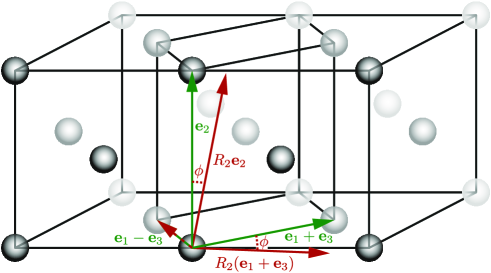
Given the transformation strain , we show how to compute the corresponding orientation relationship (OR). For simplicity, we focus on the case ; the remaining two cases can be treated analogously. From the pure Bain mechanism it is clear that the transformation results in a bcc/bct unit cell with edges along the directions , and (see Figure 1). The additional rotation in the transformation then results in a bcc/bct unit cell with edges along the directions
which form the natural basis for the bcc/bct lattice.
Noting that and we see that the change of basis matrix between fcc and bcc/bct is given by i.e. , where
| (6) |
In particular, through the matrix one can express the coordinates of the unrotated plane and direction in the new bcc/bct (-) basis and hence determine the orientation relationship. In general, the orientation relationship corresponding to is given through the matrix
| (7) |
which we henceforth call the orientation relationship matrix. We note that with , i.e. choosing the opposite sign for the rotation about simply leads to a crystallographically equivalent normal and direction. In summary, starting from the transformation , we obtain the orientation relationship
| (8) |
where the coordinates and are obtained by using the orientation relationship matrix from (7) in (6).
Conversely, suppose that an OR of the form (8) is given with the property that the normal and the direction are left unrotated by the transformation. By the above process, we can compute three possible transformation strains and corresponding OR matrices . For each OR matrix we can calculate the bcc/bct coordinates of and . For one of the matrices , the calculated coordinates must agree, up to crystallographic equivalence, with the given OR and, hence, we may uniquely identify the Bain variant , and the corresponding transformation strain , that gives rise to the OR. If the coordinates do not agree for any , then the OR cannot be compatible with the Bain mechanism.
Generating variants through crystallographic equivalence in the phase
Given a transformation strain (or equivalently the corresponding OR matrix ) we are able to generate further variants of through the application of in the reference configuration. To this end, we recall that given the fcc basis , all crystallographically equivalent fcc bases are given by for . Thus, letting as in (4) and using the identity we infer that
That is, for each , the deformation leaves the plane with normal and the direction within that plane unrotated and thus describes a strain variant of the original transformation strain . Similarly, describes the corresponding orientation relationship variant. We note that in general, it may happen (see e.g. the model) that for some and thus there can be less than 24 distinct variants for a given transformation strain (or equivalently for a given OR).
3 The NW and KS models
In this section, we derive the and models. Both models have the attractive feature of leaving a close-packed plane and a close-packed direction within that plane unrotated. Owing to this feature they seem to be the most natural candidates for OR models. To carry out the derivation we apply our unified approach from Section 2 with
The transformation with stretch component
Let us consider the second Bain variant . Noting that is an eigenvector of , we immediately deduce that, by (4), and thus is the axis of rotation. Regarding the angle of rotation we calculate
where we used that and (1). Hence, the angle of rotation is given by
| (9) |
where is the ratio of tetragonality of the bct cell. In particular, for corresponding to a bcc product lattice we obtain .
Hence, the only transformation from fcc to bcc/bct with stretch component which leaves the plane and the direction unrotated is
| (10) |
Regarding the orientation relationships corresponding to , through (10) and (7), we infer that (cf. Figure 1). Consequently,
| (11) |
Note that, as expected, the latter is a closest packed plane in the resulting bct lattice containing the bct direction . Thus for (bcc) the transformation gives rise to the OR (see Table 3) and henceforth we denote . The OR matrix between fcc and bcc is given by
and the corresponding transformation is given by
Next, we characterize the remaining variants. Following our unified approach, they are given by . Since , and we deduce that and similarly that for any . Thus there are only 12 strain variants given by
for . In particular, has a stretch component followed by a rotation of about . The corresponding OR matrices are obtained by the same conjugation. That is
for . Thus, by (11), maps the fcc normal and fcc vector to the bcc/bct normal and the bcc/bct direction (see Table A.1 in the Appendix). It is easy to verify that, for , the resulting bcc vectors are crystallographically equivalent (through ) to the bcc vector and the bcc normal , giving the variants as in Table 3. We note that the choice of sign for the 45∘ rotation about , as well as the enumeration of , has been carefully made so that the OR is obtained through . A choice of the opposite sign and/or a different enumeration of , will not alter the result but will lead to bcc/bct coordinates that are crystallographically equivalent to the ones in Table 3 through different elements of .
The transformation with stretch component
Similarly, using instead of in (4) gives rise to a rotation satisfying
| (12) |
Noting that we immediately see that and
for some angle . Let us first determine the sign of . By (12), we have that and thus For the angle itself we deduce from (5) that
| (13) |
For (bcc) this angle is given by . Hence, the only transformation from fcc to bcc/bct with stretch component which leaves the plane and the direction unrotated is
| (14) |
Regarding the corresponding orientation relationships, by (7), we deduce that
| (15) |
and, consequently,
| (16) |
These correspond to a closest packed plane in the resulting bcc/bct lattice and the close packed direction in that plane. Clearly, for (bcc), the transformation gives rise to the OR (see Table 3) and henceforth we denote . The OR matrix between fcc and bcc is then given by
and the transformation strain by
The remaining strain variants are and by (14) they are given by
In particular, leaves the close packed plane and the close packed direction within that plane unrotated. The corresponding OR variants are given by and maps the fcc normal and fcc direction to the bcc/bct normal and the bcc/bct direction (see Table A.2 in the Appendix).
The transformation with stretch component
Let us, for example, consider . Then
and thus is the only transformation with stretch component that leaves the close packed plane and the close packed direction unrotated. It is therefore the third and last solution of (4).
Just like in the derivation of the variants, care has been taken so that all odd variants correspond immediately to the entries in Table 3 and the crystallographic equivalence in the bcc/bct lattice is given by . However, unlike the variants, are distinct and thus the ORs are different. To illustrate this, let us take and investigate its action on the fcc plane with normal and the fcc direction . We have
| (17) | ||||
| and |
which are the closest packed plane and close packed direction in that plane in the resulting bct lattice. If (bcc), noting that and we obtain, up to crystallographic equivalence in the bcc lattice (by )555Nevertheless, is not a lattice invariant rotation for the resulting bct lattice. the OR associated to (cf. Table 3). The ORs for the remaining even are obtained analogously and the required crystallographic equivalence transformation in the bcc lattice is given by . Figure 2 shows the relations between all Bain, and variants.
3.1 Relation to other descriptions
In the literature (see e.g. [KMD76, RJ90, Bun13]) the ORs are sometimes described as rotations about where and the ORs as 90∘ rotations about . We show that these descriptions follow, up to crystallographic equivalence, from the above derivation. Let us start with the OR for . With the choice we obtain
and thus for some666 for , for , for and for . That is, up to crystallographic equivalence in the bcc lattice, is a rotation about (see Table 1).
| OR | OR matrix | OR | OR matrix | |
|---|---|---|---|---|
| 1 | 7 | |||
| 2 | 8 | |||
| 3 | 9 | |||
| 4 | 10 | |||
| 5 | 11 | |||
| 6 | 12 |
Next, let us consider the OR for . With the choice we obtain
and thus for some777 , i.e. up to crystallographic equivalence in the bcc lattice, is a rotation about (see Table 2).
| OR | OR matrix | OR | OR matrix | |
|---|---|---|---|---|
| 1 | 13 | |||
| 2 | 14 | |||
| 3 | 15 | |||
| 4 | 16 | |||
| 5 | 17 | |||
| 6 | 18 | |||
| 7 | 19 | |||
| 8 | 20 | |||
| 9 | 21 | |||
| 10 | 22 | |||
| 11 | 23 | |||
| 12 | 24 |
3.2 Twin relationships between KS variants
The knowledge of the transformation strains allows one to unambiguously identify pairs of variants and that are twin related, i.e. variant pairs whose relative deformation is an invariant plane strain. That is
where is the matrix with components . In particular, this implies that a fully coherent interface of normal can be formed between the two phases. We show that this can only happen between the pairs and and whenever this is the case the lattices on either side of the interface are related by a rotation about the common invariant fcc direction (cf. Table 3). We start with and assume that
| (18) |
Whenever does not leave invariant we have and and thus . Similarly, whenever does not leave invariant, i.e. , we have888For an invertible matrix , is an eigenvector of iff it is an eigenvector of . and and thus , where . Hence for it holds that
and thus, since is an eigenvector of , it must also be an eigenvector of . However, we know that this can only be the case for (cf. Table 3), a contradiction. For the remaining cases, i.e. , we have
and thus since is an eigenvector of it must also be an eigenvector of which is again, unless , a contradiction. Finally,
where is a rotation about the common fcc direction . Through conjugation with we obtain that the relative deformations between and are also invariant plane strains.
3.3 The influence of tetragonality on the orientation relationships
For many compositions of steel the -phase is not cubic () but slightly tetragonal (). For instance, the addition of carbon leads to a ratio of tetragonality approximately given by
| (19) |
for in the range – wt (see [Rob53, WC62]).999Related experiments on -- in [WW71] showed that the tetragonality does not increase for carbon above . Similarly, the addition of nitrogen instead of carbon leads to a tetragonality ratio of
for in the range – wt (after Fig. in [Nis78]). For small carbon content and certain - alloys, such as the - alloy investigated in [Nis34] and [Was35], the -phase is likely to be cubic, however, alloying additional elements such as or leads again to a tetragonal -phase.
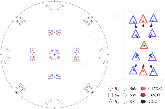
Our derivation in Section 3 takes the tetragonality of the -phase into account and the transformation strains, as well as the ORs, are derived for any ratio of tetragonality .101010Note that corresponds to an fcc lattice and thus there is no phase transformation. In particular, the angles of rotations and in (9) and (13) respectively decrease with increasing tetragonality and thus our theory predicts a narrower distribution of peaks in the pole figures. This prediction agrees very well with [RJ90] which summarises that “investigators have shown that the chemical composition of steel has a significant effect on the nature and sharpness of the final transformation texture” and that increasing alloy content (i.e. higher tetragonality) leads to sharper textures (see e.g. [RJ90, Fig. 11-16]). Figure 3 depicts the changes in the and ORs for different ratios of tetragonality obtained through (19) for a carbon content increasing from to .
4 Other orientation relationship models
In this section, we briefly comment on how our approach can be used to derive the Pitsch (see [Pit59]), Greninger-Troiano () (see [GT49]) and inverse Greninger-Troiano (see [HGJ06]) OR models.
The Pitsch model
Following [Pit59] the Pitsch ORs () are given as
| (20) |
Using our unified approach from Section 2 with and we obtain and , where . The remaining eleven Pitsch OR and strain variants are given through conjugation with . We note that for , , where is given by (9) in the derivation of the variants, and that (similarly for some ). If instead of (20) one uses the parallelisms and (as e.g. in [HGJ06, Nol04]) the resulting strains and ORs are the same. Finally, we remark that occasionally [Pit62] is also cited for the Pitsch ORs. However, the measurements in [Pit62] are for cementite which has an orthorhombic crystal structure and thus our unified approach from Section 2 does not apply directly. Nevertheless, the underlying mechanism remains applicable if in (4) one replaces the Bain strain by the respective strain required to transform austenite to cementite.
The Greninger-Troiano and inverse Greninger-Troiano models
In [GT49], Greninger-Troiano () studied a Fe-20%Ni-0.8%C crystal with and observed the following approximate parallelisms
Apart from these original ORs (up to crystallographic equivalence), several authors use slightly different approximate parallelisms as defining features of the Greninger-Troiano () orientation relationships. For instance, [BH11, TCDY02] report and and [HGJ06] uses the parallelisms
| (21) |
to approximate the ORs. Using the parallelism condition (21) our unified approach can capture the slight misorientations as an effect of the increased tetragonality of the bct lattice. With and we obtain and
with . In particular, we have and and thus for the value studied in [GT49] we obtain , and .
The inverse introduced in [HGJ06] satisfy the conditions and and as before our unified approach can be used to derive the corresponding strains and ORs. For further details on the , and also on the and ORs we refer to the Appendix.
5 Conclusions
A unified approach to derive transformation strains and orientation relationship models in steels is presented. An important aspect is the identification of strains with orientation relationships. The unified approach is used to derive the , and other models and extend them naturally to the situation of a tetragonal phase. The obtained dependence on the ratio of tetragonality seems to be in good qualitative agreement with experiments.
Acknowledgements
The research of A. M. leading to these results has received funding from the European Research Council under the European Union’s Framework Programme (FP7/2007-2013) / ERC grant n.
Appendix A Overview of orientation relationship models
A.1 Nishiyama-Wassermann (NW)
The transformation is uniquely defined through our unified approach (cf. Section 2) as the transformation that:
-
•
leaves the normal and the direction unrotated,
-
•
has pure stretch component .
The resulting transformation strain is
where . The corresponding OR matrix is
which yields the OR
The application of yields the remaining eleven ORs (cf. Table A.1). Note that, unlike Table 3, Table A.1 takes the tetragonality of the bct lattice into account and the bct vectors are given in a way that is consistent with the transformation strains and not up to crystallographic equivalence.
[ht] The NW orientation relationships. The corresponding transformation strain in each row is given by .
| ORa | fcc planeb | bcc planec | fcc directiond | bcc directione | Bain Variantf |
|---|---|---|---|---|---|
| 1 | |||||
| 2 | |||||
| 3 | |||||
| 4 | |||||
| 5 | |||||
| 6 | |||||
| 7 | |||||
| 8 | |||||
| 9 | |||||
| 10 | |||||
| 11 | |||||
| 12 |
-
a
-
b
-
c
-
d
-
e
-
f
A.2 Kurdjumov-Sachs (KS)
The transformation is uniquely defined through our unified approach (cf. Section 2) as the transformation that:
-
•
leaves the normal and the direction unrotated,
-
•
has pure stretch component .
The resulting transformation strain is
where , The corresponding OR matrix is
which yields the OR
The application of yields the remaining ORs (cf. Table A.2). Note that, unlike Table 3, Table A.2 takes the tetragonality of the bct lattice into account and the bct vectors are given in a way that is consistent with the transformation strains and not up to crystallographic equivalence.
[ht]
The orientation relationships. The corresponding transformation strain in each row is given by .
| ORa | fcc planeb | bcc planec | fcc directiond | bcc directione | Bain Variantf |
|---|---|---|---|---|---|
-
a
-
b
-
c
-
d
-
e
-
f
A.3 Pitsch (PT)
The transformation is uniquely defined through our unified approach (cf. Section 2) as the transformation that:
-
•
leaves the normal and the direction unrotated,
-
•
has pure stretch component .
The resulting transformation strain is
where . The corresponding OR matrix is
which yields the OR
The application of yields the remaining eleven ORs (cf. Table A.3).
Remark
also yields the parallelism stated in [Pit59] (for ).
[ht] The Pitsch orientation relationships. The corresponding transformation strain in each row is given by .
| ORa | fcc planeb | bcc planec | fcc directiond | bcc directione | Bain Variantf |
|---|---|---|---|---|---|
| 1 | |||||
| 2 | |||||
| 3 | |||||
| 4 | |||||
| 5 | |||||
| 6 | |||||
| 7 | |||||
| 8 | |||||
| 9 | |||||
| 10 | |||||
| 11 | |||||
| 12 |
-
a
-
b
-
c
-
d
-
e
-
f
A.4 Greninger-Troiano (GT)
The transformation is uniquely defined through our unified approach (cf. Section 2) as the transformation that:
-
•
leaves the normal and the direction unrotated,
-
•
has pure stretch component .
The resulting transformation strain is
where . The corresponding OR matrix is
which yields the OR
The application of yields the remaining ORs (cf. Table A.4).
Example
Let (as in [GT49]) then and
[ht] The orientation relationships. The corresponding transformation strain in each row is given by .
| ORa | fcc planeb | bcc planec | fcc directiond | bcc directione | Bain Variantf |
|---|---|---|---|---|---|
-
a
-
b
-
c
-
d
-
e
-
f
A.5 Inverse Greninger-Troiano (GT’)
The transformation is uniquely defined through our unified approach (cf. Section 2) as the transformation that:
-
•
leaves the normal and the direction unrotated,
-
•
has pure stretch component .
The resulting transformation strain is
where . The corresponding OR matrix is
which yields the OR
The application of yields the remaining ORs (cf. Table A.5).
[ht] The orientation relationships. The corresponding transformation strain in each row is given by .
| ORa | fcc planeb | bcc planec | fcc directiond | bcc directione | Bain Variantf |
|---|---|---|---|---|---|
-
a
-
b
-
c
-
d
-
e
-
f
Appendix B The group
The elements of in the standard basis are given by
| , | |||||
References
- [Bai24] E.C. Bain. The nature of martensite. Transactions of the Metallurgical Society of AIME, 70(1):25–47, 1924.
- [BH11] H. Bhadeshia and R. Honeycombe. Steels: Microstructure and Properties. Elsevier Science, 2011.
- [Bha03] K. Bhattacharya. Microstructure of martensite. OUP Oxford, 2003.
- [Bun13] H.J. Bunge. Texture Analysis in Materials Science: Mathematical Methods. Elsevier Science, 2013.
- [CBdC10] C. Cayron, F. Barcelo, and Y. de Carlan. The mechanisms of the fcc-bcc martensitic transformation revealed by pole figures. Acta Materialia, 58(4):1395–1402, 2010.
- [GLMJ04] Z. Guo, C.S. Lee, and J.W. Morris Jr. On coherent transformations in steel. Acta Materialia, 52(19):5511–5518, 2004.
- [GT49] A.B. Greninger and A.R. Troiano. The mechanism of martensite formation. Transactions of the Metallurgical Society of AIME, 185(9):590–598, 1949.
- [HGJ05] Y. He, S. Godet, and J.J. Jonas. Representation of misorientations in Rodrigues-Frank space: Application to the Bain, Kurdjumov-Sachs, Nishiyama-Wassermann and Pitsch orientation relationships in the Gibeon meteorite. Acta Materialia, 53(4):1179–1190, 2005.
- [HGJ06] Y. He, S. Godet, and J.J. Jonas. Observations of the Gibeon meteorite and the inverse Greninger-Troiano orientation relationship. Journal of Applied Crystallography, 39(1):72–81, 2006.
- [KM15] K. Koumatos and A. Muehlemann. The morphology of lath martensite: a new perspective. MATEC Web of Conferences: Proceedings of the 10th European Symposium on Martensitic Transformations, 33:07003, 2015.
- [KM16] K. Koumatos and A. Muehlemann. Optimality of general lattice transformations with applications to the Bain strain in steel. Proceedings of the Royal Society A: Mathematical, Physical & Engineering Sciences, 2016.
- [KMD76] J.S. Kallend, P.P. Morris, and G.J. Davies. Texture transformations - the misorientation distribution function. Acta Metallurgica, 24(4):361–370, 1976.
- [KS30] G.V. Kurdjumov and G. Sachs. Über den Mechanismus der Stahlhärtung. Zeitschrift für Physik, 64:325–343, 1930.
- [Nis34] Z. Nishiyama. X-ray investigation of the mechanism of the transformation from face-centred cubic lattice to body-centred cubic. Science Reports of the Tohoku Imperial University, Series 1: Mathematics, Physics, Chemistry, 23:637–664, 1934.
- [Nis78] Z. Nishiyama. Martensitic Transformation. Elsevier Science, 1978.
- [Nol04] G. Nolze. Determination of orientation relationships between fcc/bcc lattices by use of pole figure. In Proceedings of Channel Users Meeting, pages 37–45, 2004.
- [Ott60] H.M. Otte. The orientation of martensite in austenite. Acta Metallurgica, 8(12):892–896, 1960.
- [Pit59] W. Pitsch. The martensite transformation in thin foils of iron-nitrogen alloys. Philosophical Magazine, 4(41):577–584, 1959.
- [Pit62] W. Pitsch. Der Orientierungszusammenhang zwischen Zementit und Austenit. Acta Metallurgica, 10(9):897 – 900, 1962.
- [RJ90] R.K. Ray and J.J. Jonas. Transformation textures in steels. International Materials Reviews, 35(1):1–36, 1990.
- [Rob53] C.S. Roberts. Effect of carbon on the volume fractions and lattice parameters of retained austenite and martensite. Trans. AIME, 197(2):203–204, 1953.
- [TCDY02] M.C. Tsai, C.S. Chiou, J.S. Du, and J.R. Yang. Phase transformation in AISI 410 stainless steel. Materials Science and Engineering: A, 332(1–2):1–10, 2002.
- [Was35] G. Wassermann. Über den Mechanismus der - Umwandlung des Eisens. Mitteilungen aus dem Kaiser-Wilhelm-Institut für Eisenforschung zu Düsseldorf. Verlag Stahleisen, 1935.
- [WC62] P.G. Winchell and M. Cohen. The strength of martensite. Technical report, DTIC Document, 1962.
- [WW71] M. Watanabe and C.M. Wayman. The morphology and substructure of highly tetragonal martensites in Fe-7%Al-C steels. Metallurgical and Materials Transactions B, 2(8):2221–2227, 1971.