Terahertz plasmonic laser radiating in an ultra-narrow beam
Abstract
Plasmonic lasers (spasers) generate coherent surface-plasmon-polaritons (SPPs) and could be realized at subwavelength dimensions in metallic cavities for applications in nanoscale optics. Plasmonic cavities are also utilized for terahertz quantum-cascade lasers (QCLs), which are the brightest available solid-state sources of terahertz radiation. A long standing challenge for spasers that are utilized as nanoscale sources of radiation, is their poor coupling to the far-field radiation. Unlike conventional lasers that could produce directional beams, spasers have highly divergent radiation patterns due to their subwavelength apertures. Here, we theoretically and experimentally demonstrate a new technique for implementing distributed-feedback (DFB) that is distinct from any other previously utilized DFB schemes for semiconductor lasers. The so-termed antenna-feedback scheme leads to single-mode operation in plasmonic lasers, couples the resonant SPP mode to a highly directional far-field radiation pattern, and integrates hybrid SPPs in surrounding medium into the operation of the DFB lasers. Experimentally, the antenna-feedback method, which does not require the phase matching to a well-defined effective index, is implemented for terahertz QCLs, and single-mode terahertz QCLs with beam divergence as small as are demonstrated, which is the narrowest beam reported for any terahertz QCL to-date. Moreover, in contrast to negligible radiative-field in conventional photonic band-edge lasers, in which the periodicity follows the integer multiple of half-wavelength inside active medium, antenna-feedback breaks this integer-limit for the first time and enhances the radiative-field of lasing mode. Terahertz lasers with narrow-beam emission will find applications for integrated as well as standoff terahertz spectroscopy and sensing. The antenna-feedback scheme is generally applicable to any plasmonic laser with a Fabry-Pérot cavity irrespective of its operating wavelength, and could bring plasmonic lasers closer to practical applications.
I Introduction
A surface-plasmon-polariton (SPP) is a coupled state between electromagnetic (EM) field and electron plasma oscillations at the interface between a metal and a dielectric, for which the EM field could be confined in subwavelength dimensions normal to the surface of metal. Consequently, metallic cavities supporting SPP modes have been used to realize SPP lasers (also known as plasmonic lasers or spasers) with subwavelength dimensions bergman:spaser ; hill:smalllasers ; oulton:splasers ; berini:spplasers ; noginov:spaser . The energy in a spaser can remain confined as coherent SPPs or it can be made to leak out from the spaser as radiation. In many targeted applications in integrated optics and nanophotonics, spasers are developed as nanoscale sources of coherent electromagnetic (EM) radiation and show interesting properties such as ultrafast dynamics for applications in high-speed optical communications. Parallel-plate metallic cavities supporting SPP modes are also utilized for terahertz quantum-cascade lasers (QCLs) kohler:laser to achieve low-threshold and high-temperature performance williams:review owing to the low-loss of SPP modes at terahertz frequencies that are much smaller than the plasma frequency in metal. The most common type of plasmonic lasers with long-range SPPs, which include terahertz QCLs, utilize Fabry-Pérot type cavities in which at least one dimension is longer than the wavelength inside the dielectric hill:mimlaser ; oulton:plasmonlaser ; lu:nanolaser ; williams:metal . One of the most important challenges for such plasmonic lasers is their poor coupling to free-space radiation modes owing to the subwavelength mode confinement in the cavity, which leads to small radiative efficiency and highly divergent radiation patterns. This problem is also severe for terahertz QCLs based on metallic cavities and leads to low-output power and undesirable omnidirectional radiation patterns from Fabry-Pérot cavities adam:beam ; orlova:wirelaser .
A possible solution to achieve directionality of far-field emission from spasers is to utilize periodic structures with broad-area emission, which has been used for both short-wavelength spasers zhou:nanocavityarrays ; beijnum:holearrays ; meng:spaserarray ; yang:real ; schokker:lasing ; dorofeenko:steady as well as terahertz QCLs mahler:review11 ; sirtori:review13 . On chip phased-locked arrays kao:phase ; halioua:phaselocked or metasurface reflectors composed of multiple cavities xu:metasurface have also been utilized for directional emission in terahertz QCLs. However, edge-emitting Fabry-Pérot cavity structures with narrow cavity widths are more desirable, especially for electrically pumped spasers to achieve small operating electrical power and better heat removal from the cavity (along the width of the cavity in lateral dimension, through the substrate) for continuous-wave (cw) operation. In this paper, we theoretically and experimentally demonstrate a new technique for implementing distributed-feedback (DFB) in plasmonic lasers with Fabry-Pérot cavities, which is termed as an antenna-feedback scheme. This DFB scheme has no resemblance to the the multitude of DFB methods that have been conventionally utilized for semiconductor lasers. The key concept is to couple the guided SPP mode in a spaser’s cavity to a single-sided SPP mode that can exist in its surrounding medium by periodic perturbation of the metallic cladding in the cavity. Such a coupling is possible by choosing a Bragg grating of appropriate periodicity in the metallic film. This leads to excitation of coherent single-sided SPPs on the metallic cladding of the spaser, which couple to a narrow-beam in the far-field. The narrow beam emission is due in part to the cavity acting like an end-fire phased-array antenna at the microwave frequencies, as well as due to the large spatial extent of a coherent single-sided SPP mode that is generated on the metal film as a result of the feedback scheme. Experimentally, the antenna-feedback method is implemented for terahertz QCLs for which the method is shown to be an improvement over the recently developed third-order DFB scheme for producing directional beams amanti:dfb since it does not require any specific design considerations for phase-matching kao:dfbpm . The emitted beam is more directional and the output power is also increased due to increased radiative field by virtue of this specific scheme.
II Antenna-feedback scheme for plasmonic lasers
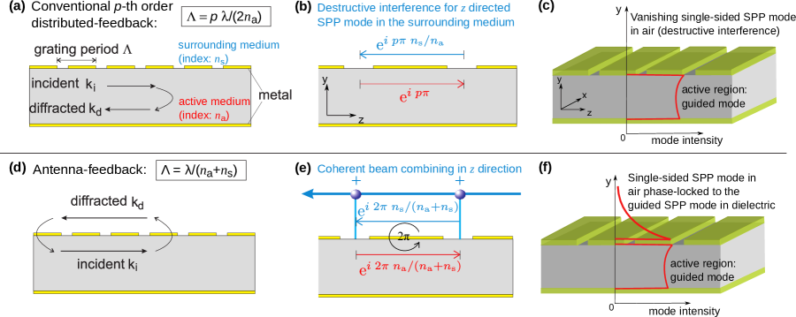
Single-mode operation in spasers with Fabry-Pérot cavities could be implemented in a straightforward manner by periodically perturbing the metallic film that supports the resonant SPP modes. The schematic in Fig. 1(a) shows an example of a periodic grating in the top metal cladding for a parallel-plate metallic cavity that could be utilized to implement conventional -th order DFB by choosing the appropriate periodicity. Since the SPP mode has maximum amplitude at the interface of metal and dielectric active medium, a periodic perturbation in the metal film could provide strong Bragg diffraction up to high-orders for the counter-propagating SPP waves inside the active medium with incident and diffracted wavevectors and respectively, such that
| (1) |
where is the grating period, is the grating wavevector, and is an integer () that specifies the diffraction order. For plane-wave like modes at frequencies far away from the plasma resonance in metal, , where is the free-space wavelength corresponding to the SPP mode and is the effective propagation index in active medium (approximately the same as refractive index of the medium), the so-called Bragg mode with is resonantly excited because it is, by design, the lowest-loss mode in the DFB cavity within the gain spectrum of the active medium. For terahertz QCLs with metallic cavities, first-order williams:corrdfb and second-order fan:surfemit ; kumar:surfemit DFBs have been implemented to achieve robust single-mode operation. However, these conventional DFB techniques do not achieve directionality of far-field radiation in both directions. There is phase mismatch for SPP waves on either side of metal claddings and destructive interference between successive apertures, as shown in Fig. 1(b) for propagating SPP waves. Therefore, no coherent single-sided SPP waves can be established on the metallic cladding in the surrounding medium as demonstrated in Fig. 1(c). Consequently, 2D photonic-crystal DFB structures have been utilized for broad-area (surface) single-mode emission chassagneux:nature ; halioua:phocrystal for which diffraction-limited beams could be achieved at the expense of large cavity dimensions.
In contrast to conventional DFB methods in which periodic gratings couple forward and backward propagating waves inside the active medium itself, the antenna-feedback scheme couples a single-sided SPP wave that travels in the surrounding medium with the SPP wave traveling inside the active medium as illustrated in Fig. 1(d). The SPP wave inside the active medium with incident wavevector is diffracted in the opposite direction in the surrounding medium with wavevector . For the first-order diffraction grating (), equation (1) results in
| (2) |
that leads to excitation of a DFB mode with , which is different from any of the -th order DFB modes that occur at . Hence, the antenna-feedback mode could always be excited by just selecting the appropriate grating period such that the wavelength occurs close to the peak-gain wavelength in the active-medium. For GaAs/AlGaAs based terahertz QCLs, , , and hence for a chosen grating-period , the first-order DFB, antenna-feedback, and second-order DFB modes occur at wavelengths , , and respectively. The typical gain-bandwidth of terahertz QCLs is less than of the peak-gain wavelength, which suggests that the grating has to be designed specifically to excite the antenna-feedback mode.
The antenna-feedback scheme leads to excitation of a coherent single-sided SPP standing-wave on the metallic cladding of the spaser, which is phase-locked to the resonant-cavity SPP mode inside the active medium as shown in Fig. 1(f).. Both waves maintain exact same phase relation at each aperture location, where they exchange electromagnetic (EM) energy with each other due to diffraction as illustrated in Fig. 1(e). The SPP wave in the surrounding medium is excited due to scattering of EM field at apertures that generates a combination of propagating quasi-cylindrical waves and SPPs lalanne:creepingwave2 ; babuty:mirspsource that propagate along the surface of the metal-film. The scattered waves thus generated at each aperture superimpose constructively in only the end-fire () direction owing to the phase-condition thus established at each aperture. For coupling to far-field radiation, the radiation is therefore analogous to that from an end-fire phased array antenna that produces a narrow beam in both and directions.
A third-order DFB technique was recently shown to achieve emission in a narrow beam for terahertz QCLs with Fabry-Pérot cavities amanti:dfb . It can achieve high directionality for the radiated beam in both directions perpendicular to propagation, so long as the effective propagation index of the SPP wave inside the active medium could be made by complex deep dry etching in the slits amanti:dfb or lateral corrugated geometry amanti:dfbcw . The so-called phase matching condition is possible for GaAs-based QCLs by cavity engineering kao:dfbpm since the is close to . The antenna-feedback technique in this work offers similar outcome as a perfectly matched third-order DFB with improved directionality as well as a novel outcoupling mechanism of the radiated beam from terahertz QCLs. It is to be noted that the antenna-feedback scheme is automatically phase-matched and hence it could be utilized for any type of spaser without any restrictions on the required index in the active medium.
III Simulation results
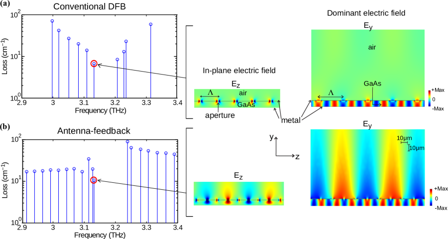
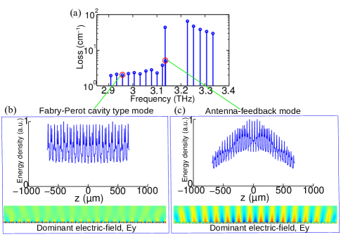
Figure 2 shows comparison of the eigenmode spectrum of a terahertz QCL cavity with conventional DFB, taking third-order DFB as an example versus antenna-feedback gratings computed using a finite-element solver comsol:ref . The occurrence of band-gaps in the spectra is indicative of the DFB effect. In both cases, the lower-frequency band-edge mode is the lowest-loss mode by way of DFB action, since the DFB modes result in a standing-wave being established along the length of the cavity with an envelope shape that vanishes close to the longitudinal boundaries (end-facets). For antenna-feedback grating, a standing-wave for the single-sided SPP wave is additionally established in air, as can be seen from the field-plot of the band-edge mode in Fig. 2(b). In contrast, third-order DFB leads to negligible amplitude of the single-sided SPP wave in air, as mentioned previously and illustrated schematically in Fig. 1(c). For the dominant TM polarized (Ey) electric field of antenna-feedback, the hybrid SPPs mode bound to the top metal layer consists of both quasi-cylindrical waves and SPPs, which are evanescent-field with a free-space propagation constant. Particularly at long wavelengths, such as mid infrared and THz region, SPPs and quasi-cylindrical waves complexly mix with each other lalanne:creepingwave2 , contributing to the large spatial extent of SPP mode in surrounding medium as shown in Fig. 2(b), which does not exist for any conventional DFB, such as first-order, second-order and third-order DFB. In addition, hybrid SPPs on top of metallic grating and standing-wave inside laser cavity show clearly different periodicity, with the ratio of free space wavelength over guided wavelength, which further confirms that the excitation of the coherent SPP wave on both side of top metallic surface contribute to feedback and coupling mechanism with antenna-feedback scheme. The absorbing boundaries at the longitudinal ends of the cavity olivier:plasmon increase the relative loss of the modes that are further away from the band-edge mode, which helps in mode discrimination and will lead to excitation of the desired band-edge mode for single-mode operation of the spaser. The active region and metal layers are modeled as lossless since the exact loss contribution due to each is not clear in literature for terahertz QCLs at cryogenic temperatures. If lossy metal is used, the relative loss of various resonant modes for the DFB cavities are not impacted and neither are the mode-shapes and the corresponding resonant frequencies. For the band-edge modes in Fig. 2(a) and Fig. 2(b), a loss of was estimated as a contribution from the absorbing boundaries. Consequently, the radiative (outcoupling) loss of of the third-order DFB is as compared to for the antenna-feedback. The radiative loss of the third-order DFB is smaller since the band-edge mode has zeros of the radiative field () being located at each aperture, since the grating period is integer multiple of half-wavelengths in the GaAs/AlGaAs active medium (, where ). Such a low-outcoupling efficiency is also existent in surface-emitting terahertz QCLs with second-order DFB kumar:surfemit . For the cavity with antenna-feedback, the radiative loss is higher because the grating period is not an integer multiple of half-wavelengths inside the active medium () that leads to large amplitudes of the radiative-field () in alternating apertures as shown in the figure. As a consequence, the output power from terahertz QCLs with antenna-feedback should be greater than that with conventional DFB gratings, which is an additional advantage of the antenna-feedback scheme for terahertz QCLs. This was also verified experimentally from the measured output power. The recently developed second-order DFB QCLs with graded periodicity xu:aperiodic achieve high-power emission for the same reason, i. e. non-zero radiative field under the metallic apertures.
IV Experimental demonstration of antenna-feedback for THz QCLs
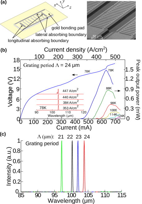
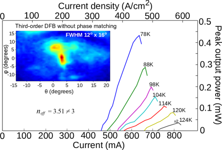
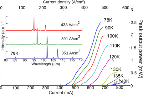
Figure 3 shows experimental results from terahertz QCLs implemented with antenna-feedback gratings. Details about fabrication and measurement methods are presented in supplementary material (section S1). Fig. 3(b) shows representative - curves versus heat-sink temperature for a QCL with . The QCL operated up to a temperature of . In comparison, multi-mode Fabry-Pérot cavity QCLs on the same chip that did not include longitudinal or lateral absorbing boundaries operated up to . Light-current characteristics and spectra at different bias with Fabry-Pérot cavity are shown in supplementary material (section S3). The temperature degradation due to absorbing boundaries is relatively small and similar to previous reports of DFB terahertz QCLs kumar:surfemit . The inset shows measured spectra at different bias at . Most QCLs tested with different grating periods showed robust single-mode operation except close to peak-bias when a second-mode was excited for some devices at a shorter-wavelength, which suggests it is likely due to a higher-order lateral mode being excited due to spatial-hole burning in the cavity. Peak-power output of was detected from the antenna-feedback QCL measured directly at the detector without using any collecting optics. For comparison, a terahertz QCL with third-order DFB (without phase matching) and similar dimensions was also fabricated on the same chip, which operated up to a similar temperature of and emitted peak-power output of (see supplementary material, section S3). The antenna-feedback gratings lead to greater radiative outcoupling compared to conventional DFB schemes for terahertz QCLs, as discussed in the previous section.
Fig. 3(c) shows spectra measured from four different terahertz QCLs with antenna-feedback gratings of different grating periods . The single-mode spectra scales linearly with , which is the clearest proof that the feedback mechanism works as expected and the lower band-edge mode is selectively excited in each case. Using from equation (2), the effective propagation index of the SPP mode in the active medium is calculated as , , , and for QCLs with of , , , and respectively. The effective mode-index decreases because a larger introduces larger sized apertures in the metal film since the grating duty-cycle was kept same for all devices. Consequently, a greater amount of field couples to the single-sided SPP mode in air for increasing , thereby reducing the modal confinement in the active medium that reduces the propagation index of the guided SPP mode further.
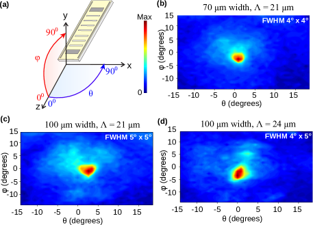
Experimental far-field beam patterns for antenna-feedback QCLs with varying designed parameters are shown in Fig. 4. Single-lobed beams in both lateral () and vertical () directions were measured for all QCLs. As shown in Fig. 4(b), the full-width half-maximum (FWHM) for the QCL with width, is , which is the narrowest reported beam-profile from any terahertz QCL to-date. In contrast, previous schemes for emission in a narrow-beam have resulted in divergence angles of using very long () cavities and a phased-matched third-order DFB scheme kao:dfbpm and using broad-area devices with 2D photonic-crystals halioua:phocrystal for single-mode terahertz QCLs, and liang:collimated and yu:spoof for multi-mode QCLs using metamaterial collimators. Figs. 4(c) and 4(d) show representative beam patterns from QCLs with wider cavities of width, for the smallest and largest in the range of fabricated devices respectively. The beam divergence is relatively independent of as expected. More importantly, the measurements show that the wider cavities result in a slightly broader beam. Such a result is counter-intuitive because typically a laser emits in a narrower beam as its cavity’s dimensions are increased due to an increase in the size of emitting aperture. Such a behavior is unique for a spaser with antenna-feedback, and is discussed along with full-wave 3D FEM simulation of the beam pattern in supplementary material (section S2). It can be argued that the size of the beam could be further narrowed by utilizing narrower cavities for terahertz QCLs, which will be extremely beneficial to develop cw sources of narrow-beam coherent terahertz radiation.
V Conclusion
In this article, we have presented a novel antenna-feedback scheme to achieve single-mode operation and a highly directional far-field radiation pattern from plasmonic lasers with subwavelength apertures and Fabry-Pérot type cavities. It is conceptually different from any other previously utilized DFB schemes for solid-state lasers, and is based on phase-locking of a single-sided surface-plasmon-polariton (SPP) mode on (one of) the metal film(s) in the spaser’s cavity with the guided SPP mode inside the spaser’s active medium. The phase-locking is established due to strong Bragg diffraction of the SPP modes by periodically perforating the metal film in the form of a grating of holes or slits. The uniqueness of the method lies in the specific value of the grating’s period, which leads to the spaser’s cavity radiating like an end-fire phased-array antenna for the excited DFB mode. Additionally, coherent single-sided SPPs are also generated on the metal film that have a large spatial extent in the surrounding medium of the laser’s cavity, which could have important implications for applications in integrated plasmonics. Coherent SPPs with large spatial extent could make it easy to couple SPP waves from the plasmonic lasers to other photonic components, and could also potentially be utilized for plasmonic sensing. Experimentally, the scheme is implemented in terahertz QCLs with subwavelength metallic cavities. A beam-divergence angle as small as is achieved for single-mode QCLs, which is narrower than that achieved with any other previously reported schemes for terahertz QCLs with periodic photonic structures. Compared with the third-order DFB method, the new antenna-feedback scheme is easier to implement for fabrication by standard lithography techniques without any other complex fabrication technique to precisely match a well defined effective mode index, and achieves a superior radiative outcoupling owing to the fact that the grating period is not an integer multiple of half-wavelengths of the standing SPP-wave inside the active medium. Terahertz QCLs with antenna-feedback could lead to development of new modalities for terahertz spectroscopic sensing and wavelength tunability due to access of a coherent terahertz SPP wave on top of the QCL’s cavity, possibilities of sensing and imaging at standoff distances of few tens of meters, and development of integrated terahertz laser arrays with a broad spectral coverage for applications in terahertz absorption spectroscopy.
Supplementary Materials
See supplementary materials section for additional supporting content.
References
- (1) D. J. Bergman and M. I. Stockman, “Surface plasmon amplification by stimulated emission of radiation: Quantum generation of coherent surface plasmons in nanosystems,” Phys. Rev. Lett. 90, 027402 (2003).
- (2) M. T. Hill and M. C. Gather, “Advances in small lasers,” Nat. Photon. 8, 908 (2014).
- (3) R. F. Oulton, “Surface plasmon lasers: sources of nanoscopic light,” Mater. Today 15, 26 (2012).
- (4) P. Berini and I. D. Leon, “Surface plasmon-polariton amplifiers and lasers,” Nat. Photon. 6, 16 (2012).
- (5) M. A. Noginov, G. Zhu, A. M. Belgrave, R. Bakker, V. M. Shalaev, E. E. Narimanov, S. Stout, E. Herz, T. Suteewong, and U. Wiesner, “Demonstration of a spaser-based nanolaser,” Nature 460, 1110 (2009).
- (6) R. Köhler, A. Tredicucci, F. Beltram, H. E. Beere, E. H. Linfield, A. G. Davies, D. A. Ritchie, R. C. Iotti, and F. Rossi, “Terahertz semiconductor-heterostructure laser,” Nature 417, 156–159 (2002).
- (7) B. S. Williams, “Terahertz quantum-cascade lasers,” Nat. Photon. 1, 517–525 (2007).
- (8) M. T. Hill, M. Marell, E. S. P. Leong, B. Smalbrugge, Y. Zhu, M. Sun, P. J. van Veldhoven, E. J. Geluk, F. Karouta, Y.-S. Oei, R. Nötzel, C.-Z. Ning, and M. K. Smit, “Lasing in metal-insulator-metal sub-wavelength plasmonic waveguides,” Opt. Express 17, 11107 (2009).
- (9) R. F. Oulton, V. J. Sorger, T. Zentgraf, R.-M. Ma, C. Gladden, L. Dai, G. Bartal, and X. Zhang, “Plasmon lasers at deep subwavelength scale,” Nature 461, 629 (2009).
- (10) Y.-J. Lu, J. Kim, H.-Y. Chen, C. Wu, N. Dabidian, C. E. Sanders, C.-Y. Wang, M.-Y. Lu, B.-H. Li, X. Qiu, W.-H. Chang, L.-J. Chen, G. Shvets, C.-K. Shih, and S. Gwo, “Plasmonic nanolaser using epitaxially grown silver film,” Science 337, 450 (2012).
- (11) B. S. Williams, S. Kumar, H. Callebaut, Q. Hu, and J. L. Reno, “Terahertz quantum-cascade laser at m using metal waveguide for mode confinement,” Appl. Phys. Lett. 83, 2124–2126 (2003).
- (12) A. J. L. Adam, I. Kašalynas, J. N. Hovenier, T. O. Klaassen, J. R. Gao, E. E. Orlova, B. S. Williams, S. Kumar, Q. Hu, and J. L. Reno, “Beam patterns of terahertz quantum cascade lasers with subwavelength cavity dimensions,” Appl. Phys. Lett. 88, 151105 (2006).
- (13) E. E. Orlova, J. N. Hovenier, T. O. Klaassen, I. Kašalynas, A. J. L. Adam, J. R. Gao, T. M. Klapwijk, B. S. Williams, S. Kumar, Q. Hu, and J. L. Reno, “Antenna model for wire lasers,” Phys. Rev. Lett. 96, 173904 (2006).
- (14) W. Zhou, M. Dridi, J. Y. Suh, C. H. Kim, D. T. Co, M. R. Wasielewski, G. C. Schatz, and T. W. Odom, “Lasing action in strongly coupled plasmonic nanocavity arrays,” Nat. Nanotech. 8, 506 (2013).
- (15) F. van Beijnum, P. J. van Veldhoven, E. J. Geluk, M. J. A. de Dood, G. W. ’t Hooft, and M. P. van Exter, “Surface plasmon lasing observed in metal hole arrays,” Phys. Rev. Lett. 110, 206802 (2013).
- (16) X. Meng, J. Liu, A. V. Kildishev, and V. M. Shalaev, “Highly directional spaser array for the red wavelength region,” Laser & Photon. Rev. 8, 896 (2014).
- (17) A. Yang, T. B. Hoang, M. Dridi, C. Deeb, M. H. Mikkelsen, G. C. Schatz, and T. W. Odom, “Real-time tunable lasing from plasmonic nanocavity arrays,” Nature Comm. 6, 6939 (2015).
- (18) A. H. Schokker and A. F. Koenderink, “Lasing at the band edges of plasmonic lattices,” Phys. Rev. B 90, 155452 (2014).
- (19) A. V. Dorofeenko, A. A. Zyablovsky, A. P. Vinogradov, E. S. Andrianov, A. A. Pukhov, and A. A. Lisyansky, “Steady state superradiance of a 2D-spaser array,” Opt. Express 21, 14539–14547 (2013).
- (20) L. Mahler and A. Tredicucci, “Photonic engineering of surface-emitting terahertz quantum cascade lasers,” Laser & Photon. Rev. 5, 647–658 (2011).
- (21) C. Sirtori, S. Barbieri, and R. Collombelli, “Wave engineering with THz quantum cascade lasers,” Nat. Photon. 7, 691 (2013).
- (22) T.-Y. Kao, Q. Hu, and J. L. Reno, “Phase-locked arrays of surface-emitting terahertz quantum-cascade lasers,” Appl. Phys. Lett. 96, 101106 (2010).
- (23) Y. Halioua, G. Xu, S. Moumdji, L. Li, J. Zhu, E. H. Linfield, A. G. Davies, H. E. Beere, D. A. Ritchie, and R. Colombelli, “Phase-locked arrays of surface-emitting graded-photonic-heterostructure terahertz semiconductor lasers,” Opt. Express 23, 6915 (2015).
- (24) L. Xu, C. A. Curwen, P. W. Hon, Q.-S. Chen, T. Itoh, and B. S. Williams, “Metasurface external cavity laser,” Appl. Phys. Lett. 107, 221105 (2015).
- (25) M. I. Amanti, M. Fischer, G. Scalari, M. Beck, and J. Faist, “Low-divergence single-mode terahertz quantum cascade laser,” Nat. Photon. 3, 586–590 (2009).
- (26) T. Y. Kao, Q. Hu, and J. L. Reno, “Perfectly phase-matched third-order DFB THz quantum-cascade lasers,” Opt. Lett. 37, 2070 (2012).
- (27) B. S. Williams, S. Kumar, Q. Hu, and J. L. Reno, “Distributed-feedback terahertz quantum-cascade lasers with laterally corrugated metal waveguides,” Opt. Lett. 30, 2909 (2005).
- (28) J. A. Fan, M. A. Belkin, F. Capasso, S. Khanna, M. Lachab, A. G. Davies, and E. H. Linfield, “Surface emitting terahertz quantum cascade laser with a double-metal waveguide,” Opt. Express 14, 11672 (2007).
- (29) S. Kumar, B. S. Williams, Q. Qin, A. W. M. Lee, Q. Hu, and J. L. Reno, “Surface-emitting distributed feedback terahertz quantum-cascade lasers in metal-metal waveguides,” Opt. Express 15, 113 (2007).
- (30) Y. Chassagneux, R. Colombelli, W. Maineult, S. Barbieri, H. E. Beere, D. A. Ritchie, S. P. Khanna, E. H. Linfield, and A. G. Davies, “Electrically pumped photonic-crystal terahertz lasers controlled by boundary conditions,” Nature 457, 174 (2009).
- (31) Y. Halioua, G. Xu, S. Moumdji, L. H. Li, A. G. Davies, E. H. Linfield, and R. Colombelli, “THz quantum cascade lasers operating on the radiative modes of a 2D photonic crystal,” Opt. Lett. 39, 3962 (2014).
- (32) P. Lalanne, J. Hugonin, H. Liu, and B. Wang, “A microscopic view of the electromagnetic properties of sub- metallic surfaces,” Surf. Sci. Rep. 64, 453 (2009).
- (33) A. Babuty, A. Bousseksou, J.-P. Tetienne, I. M. Doyen, C. Sirtori, G. Beaudoin, I. Sagnes, Y. D. Wilde, and R. Colombelli, “Semiconductor surface plasmon sources,” Phys. Rev. Lett. 104, 226806 (2010).
- (34) M. I. Amanti, G. Scalari, F. Castellano, M. Beck, and J. Faist, “Low divergence terahertz photonic-wire laser,” Opt. Express 18, 6390 (2010).
- (35) COMSOL 4.4, a finite-element partial differential equation solver from COMSOL Inc.
- (36) O. Demichel, L. Mahler, T. Losco, C. Mauro, R. Green, A. Tredicucci, J. Xu, F. Beltram, H. E. Beere, D. A. Ritchie, and V. Tamošinuas, “Surface plasmon photonic structures in terahertz quantum cascade lasers,” Opt. Express 14, 5335 (2006).
- (37) G. Xu, R. Colombelli, S. P. Khanna, A. Belarouci, X. Letartre, L. Li, E. H. Linfield, A. G. Davies, H. E. Beere, and D. A. Ritchie, “Efficient power extraction in surface-emitting semiconductor lasers using graded photonic heterostructures,” Nature Comm. 3, 952 (2012).
- (38) G. Liang, E. Dupont, S. Fathololoumi, Z. R. Wasilewski, D. Ban, H. K. Liang, Y. Zhang, S. F. Yu, L. H. Li, A. G. Davies, E. H. Linfield, H. C. Liu, and Q. J. Wang, “Planar integrated metasurfaces for highly-collimated terahertz quantum cascade lasers,” Sci. Rep. 4, 7083 (2014).
- (39) N. Yu, Q. J. Wang, M. A. Kats, J. A. Fan, S. P. Khanna, L. Li, A. G. Davies, E. H. Linfield, and F. Capasso, “Designer spoof surface plasmon structures collimate terahertz laser beams,” Nat. Materials 9, 730 (2010).
- (40) S. Khanal, L. Zhao, J. L. Reno, and S. Kumar, “Temperature performance of terahertz quantum-cascade lasers with resonant phonon active-regions,” J. Opt 16, 094001 (2014).
- (41) C. A. Balanis, Antenna Theory: Analysis and Design (Wiley-Interscience, 2005), 3rd ed.
- (42) C. Boyle, C. Sigler, J. Kirch, D. Lindberg III, T. Earles, D. Botez, and L. Mawst, “High-power, surface-emitting quantum cascade laser operating in a symmetric grating mode,” Appl. Phys. Lett. 108, 121107 (2016).
Funding Information
National Science Foundation (NSF) (ECCS 1128562, ECCS 1351142, CMMI 1437168).
Acknowledgments
This work is performed, in part, at the Center for Integrated Nanotechnologies, a U.S. Department of Energy (DOE), Office of Basic Energy Sciences user facility. Sandia National Laboratories is a multiprogram laboratory managed and operated by Sandia Corporation, a wholly owned subsidiary of Lockheed Martin Corporation, for the U.S. DOE’s National Nuclear Security Administration under contract DE-AC04-94AL85000.
Competing financial interests
A United States patent application (pending) for the described technology has been filed through Lehigh University (application number 14/984,652, filed on Dec. 30, 2015).
Terahertz plasmonic laser radiating in an ultra-narrow beam
C. Wu et al.
Supplementary Materials
S1 Materials and Methods
Fabrication and measurement details
The active-medium of the QCLs is based on a three-well resonant-phonon design with GaAs/ superlattice (design RTRP3W197, wafer number VB0464), which is described in Ref. khanal:rpreview, , and was grown by molecular-beam epitaxy. The QCL superlattice is thick with an average -doping of , and surrounded by and thick highly-doped GaAs contact layers at on either side of the superlattice. Fabrication of QCLs with parallel-plate metallic cavities followed a Cu-Cu thermocompression wafer bonding technique as in Ref. kumar:surfemit, with standard optical contact lithography. Following wafer-bonding and substrate removal, positive-resist lithography was used to selectively etch away the thick highly-doped GaAs layer from all locations where top-metal cladding would exist on individual cavities except in wide regions at the outer rectangular boundaries of the top-metal layer due to overlapping mask layers. The removal of this layer beneath the top-metal does not impact electrical transport significantly except adding a small voltage drop at the top contact during QCL operation. Importantly, this lithography step allows radiative outcoupling from the apertures in the finally fabricated QCL cavities; and simultaneously serves to implement longitudinal and lateral absorbing boundaries as illustrated in Fig. 3(a) by leaving the highly-doped GaAs layer exposed at both longitudinal and lateral edges of the QCL cavity. The absorbing boundaries result in a highly lossy propagation of the SPP modes in those regions olivier:plasmon . While the longitudinal boundaries help in DFB mode discrimination, the lateral boundaries are useful to eliminate higher-order lateral guided modes by making them more lossy in comparison to the fundamental mode kumar:surfemit ; chassagneux:nature ; amanti:dfb .
Ti/Au metal layers of thickness nm were used as the top metal cladding, using an image-reversal lithography mask for implementing gratings in the metal layers. Another positive-resist lithography step was used to cover the grating-metal with photoresist to be used as a mask for wet-etching of ridges in a H2SO4:H2O2:H2O :: solution for minutes. After etching the thick superlattice active region when the bottom metal layer is exposed, an over-etch of minute was followed up to reduce the slope on the sidewalls of the QCL’s cavities to allow for a more uniform current-density distribution through the height of the cavity (in direction). A Ti/Au contact was used as the backside-metal contact for the finally fabricated QCL chips to assist in soldering. Before deposition of backside-metal of the wafer, the substrate was mechanically polished down to a thickness of to improve heat-sinking.

For measurements, a cleaved chip consisting of QCLs with antenna-feedback gratings of different periods along with some Fabry-Pérot ridge QCLs and third-order DFB QCLs was In-soldered on a Cu block, the QCL to be tested was wire-bonded for electrical biasing, and the Cu block was mounted on the cold-stage of a liquid Nitrogen vacuum cryostat for measurements. Initial measurements of the fabricated QCL cavities did not yield lasing devices at . It was then realized that the wide lateral absorbing boundaries on each side were perhaps introducing high optical losses in the cavities. The finally fabricated wafers were then etched again (post-fabrication) in a H2SO4:H2O2:H2O :: solution for seconds, which is likely to etch away most of the exposed highly-doped GaAs layer. However, wide highly-doped GaAs layer remains unetched underneath the top-metal cladding on all four outer boundaries of the cladding, which serves to perform the role of an absorbing region. The post-etched devices lased upon re-testing, and their robust single-mode operation suggests that both lateral and longitudinal absorbing boundaries were able to suppress undesired resonant-modes in the cavity as desired.
The emitted optical power was measured with a deuterated triglycine sulfate pyroelectric detector (DTGS) pyroelectric detector and calibrated with a terahertz thermopile powermeter (ScienTech model AC2500H) without any optical component or cone collecting optic inside the cryostat to improve collection of radiated power in the case of DFB QCLs. (A Winston cone was used to collect power, but only for the Fabry-Pérot-cavity QCL reported in Fig. S3.) The spectra were measured at in linear-scan mode with a resolution of ( GHz) using a Bruker Fourier-transform infrared spectrometer (FTIR) under vacuum, with a room-temperature DTGS detector placed inside the FTIR. Far-field radiation patterns were measured with a DTGS pyroelectric cell detector mounted on a computer-controlled two-axis ( plane) moving stage in the end-fire () direction at a distance of mm from the QCLs’ end-facets. The detector’s size leads to spatial averaging of the measured beam with a step-size of , which has a negligible impact on the measured beam-width.
Modeling
Finite-element (FEM) simulations were performed using a commercially available software comsol:ref . The eigenmodes of the DFB cavities are computed using an eigenfrequency solver. The loss in absorbing boundaries of the cavity is implemented using a complex dielectric constant computed using Drude-model kumar:surfemit . The imaginary part of the computed eigenfrequencies is used to compute the propagation loss of the resonant-cavity modes in the units of inverse of length. The active region is modeled as lossless and the metal is modeled to be perfect electrical conductors, in which case, the computed loss is the sum of loss at absorbing boundaries as well as that due to radiation (outcoupling). The thickness of the metallic layer is nm in simulation. The relative losses of various resonant modes for the DFB cavities are not changed and neither are the mode-shapes and the corresponding resonant frequencies when using lossy metal, or when the thickness of the metallic film are altered (as long as it is kept significantly thinner than that of the active region). For the 2D simulations (cavities of infinite-width) the far-field boundaries are modeled as absorbing layers as described in Ref. kumar:surfemit . For 3D simulations, the in-built perfectly matched layers in the FEM solver were utilized to model the far-field boundaries.
S2 Full-wave 3D simulation for radiation-patterns
The narrow-beam emission from plasmonic lasers with antenna-feedback is due to a combination of two factors that are related to the radiative behavior of phased-array antennas. In addition to the array-factor that leads to narrower beams for more number of elements in a phased-array (i. e. in this case, a longer length of the spaser’s cavity), the far-field radiation pattern is additionally narrowed owing to an element-factor, which is defined as the far-field radiation pattern due to an individual emitter of the phased-array balanis:antenna . The large spatial extent of the single-sided SPP wave in the surrounding medium results in a narrower element-factor compared to an omnidirectional point-source emitter.
As measured experimentally and shown in Fig. 4, the antenna-feedback terahertz QCL cavities with a narrower width of resulted in a beam with smaller divergence as compared to the wide cavity. This seemingly unique behavior from antenna-feedback QCLs serves to further validate the concept of the specific feedback scheme, in which the cavity radiates like a phased-array antenna. A narrower cavity causes greater lateral spread of the single-sided SPP mode (in the dimension) in the surrounding medium, especially when the cavity’s width is sub-wavelength. A single-sided SPP mode with a broader cross-section in the plane will lead to a more directional far-field radiation pattern owing to a narrower element-factor for the phased-array antenna structure.
To further validate the experimental results of Fig. 4, full-wave 3D FEM simulations were carried out for terahertz QCL cavities with antenna-feedback. Figure S1 shows the computed far-field radiation patterns for band-edge DFB mode for terahertz QCL cavities implemented with antenna-feedback gratings in the top metal cladding. The in-built perfectly-matched layers (PMLs) in the FEM solver comsol:ref serve as an effective absorbing boundary for computation of the radiation pattern. The PMLs’ parameters are coarsely adjusted to achieve minimum reflection at terahertz frequencies and transform the propagating waves to exponentially decaying waves. The PMLs are placed far enough to avoid interaction with the single-side SPP standing-wave in the near-field of the cavity. Considering the computer’s memory limitations, laterally absorbing boundaries are not modeled in the cavity, which does not impact the simulation’s results since the DFB mode could always be found, even though it is not the lowest loss mode in the eigenmode spectrum of the cavity due to other higher order lateral modes that can have even lower propagation loss. All metal layers are modeled as perfectly conducting surfaces to limit the mesh size in the geometry. In order to set up a far-field calculation, a far-field domain node is implemented that is a single closed surface surrounding all radiating apertures in the cavity. The distribution of far EM field is based on the Fourier transform of the near-field as implemented in the FEM solver. Simulated 3D beam patterns demonstrate single-lobed beams with narrow divergence for the band-edge mode with antenna-feedback as shown in the figure. The shape and FWHM of the computed radiation-pattern is in close agreement with the experimentally measured beams that are shown in Fig. 4. The FWHM of simulated beam patterns is slightly larger than that of the measured results. The difference are likely due to the relative simplification of implemented 3D model, which does not account for the sloped sidewall profile of the ridges and also the fact the ground plane around the QCL’s cavity is different for the measured chip as compared to that in the simulated geometry.
S3 Experimental characteristics of third-order DFB QCL and a Fabry-Pérot-cavity QCL
Figure S2 shows - characteristics of a representative terahertz QCL with third-order DFB without well defined phase-matching condition that was fabricated on the same chip by standard lithography to pattern grating on top metallic layer, and with similar dimensions as that of the antenna-feedback QCLs whose data is reported in Fig. 3. Using the phase condition as determined from equation 1 for (third-order DFB), an effective-mode index of is estimated for the resonant-cavity SPP mode in the active medium of the cavity. For ideal phase-matching, a mode-index value of is required, hence the phased-matching condition is not satisfied for this QCL. Consequently, the measured FWHM of the far-field radiation pattern for this QCL is not as good as that for phased-matched third-order DFB QCLs with reduced effective mode index kao:dfbpm ; amanti:dfb ; amanti:dfbcw . Elongated and multi-lobed beam pattern for third-order DFB when refractive index is close to is observed in Ref. amanti:dfb . The peak output power for the third-order DFB QCL without phase matching is at , which is about three times less than that obtained for the antenna-feedback QCL with similar dimensions lasing at similar frequency. The output power slope efficiencies at are mW/A and mW/A respectively for the third-order DFB QCL and antenna-feedback QCL respectively. The optical power was measured without cone collecting optics. The relative differences in the measured optical power are in good agreement with the radiative losses estimated via 2D FEM simulations for similar cavity dimensions as in Fig. 2. The maximum operating temperature of this QCL is almost similar to that of the antenna-feedback QCL, which suggests that radiative loss is relatively a small fraction of the overall waveguide loss in both types of DFB QCL cavities. This also suggests that there is a scope for enhancing radiative efficiency to increase optical power output without causing a significant degradation in temperature performance of terahertz QCLs with antenna-feedback. Calculation of surface-outcoupling efficiency as in Ref. boyle:high is outside the scope of this work due to large uncertainty in the absolute loss contribution of metal layers, absorbing boundaries, as well as the active region itself. The optimized phase-matched third-order DFB amanti:dfbcw with bound-to-continuum design shows lower current-density and higher efficiency without absorbing regions. Since the feedback of laser mode is achieved by SPP mode propagating on the surface for antenna-feedback, technique of covering waveguide sidewall with metal kumar:surfemit or lateral corrugated grating amanti:dfbcw , which does not absorb effective outcoupled laser radiation from antenna-feedback, can replace lateral absorber layer here and will further enhance the outcoupling efficiency. L-I characteristics at different heat-sink temperature of a representative terahertz QCL with Fabry-Pérot (FP) cavity is shown in Fig. S3. Exposed highly-doped lossy contact layer serving as absorber introduces temperature degradation for DFB cavity. Because sub-wavelength mode confinement in FP cavities results in highly divergent output beams of THz QCLs with parallel-plate metallic cavities, output power is measured with a Winston cone and the detector was placed adjacent to the cryostat window. Diameter of the circular opening of cone is . Frequency of gain medium covers to at .
S4 Analysis of antenna-feedback scheme by 2D and 3D simulations
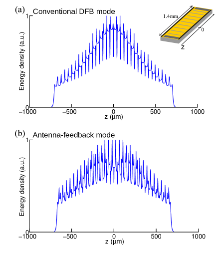
Figure S4 shows energy-density profile for the resonant band-edge modes of the cavities with third-order DFB and antenna-feedback schemes respectively, along the entire length of the cavity (mm). Energy-density is calculated and summed up along the cavity’s height () from 2D simulations (that effectively model cavities of infinite width). The eigenmode spectra and electric-field distributions for the cavities are shown in Fig. 2. Both third-order DFB and antenna-feedback schemes show non-uniform envelope shapes, which gradually decrease from the center to the end-facets of cavity and provide indication of typical DFB action due to coupling of propagating waves along the length of cavity as per the corresponding schematics in Fig. 1.
A thin highly-doped GaAs layer below the top-metal cladding was left unetched at the regions close to longitudinal facets, serving as the longitudinal absorbing boundary to ensure the excitation of the desired antenna-feedback mode as the lowest-loss lasing mode. Firstly, such absorbing boundaries reduce the end-facet reflectivities that strengthens the distributed-feedback coupling for the antenna-feedback scheme. Secondly, the longitudinal absorber boundaries play an important role in providing the necessary mechanism for mode-discrimination, to selectively excite the desired band-edge antenna-feedback mode for lasing. Figure S5(a) shows that eigenmode spectrum of antenna-feedback scheme without longitudinal absorbing boundaries. There exist the Fabry-Perot type modes with uniform energy density profile along the whole length of laser cavity and large electric field distribution close to end facets of the cavity, as shown in Fig. S5(b). However, the loss of such modes is small due to highly reflective end-facets. The desired antenna-feedback mode, located at the lower bandedge, shows non-uniform energy-density profile along the length of cavities as an indicator of DFB action and strong coupling between plasmonic mode on top of metallic layer and guided mode in the active core, as seen from Fig. S5(c). However, its radiative loss is higher due to the improved and large radiative field of antenna-feedback mode and hence, it cannot be excited for lasing in the absence of longitudinal absorbing boundaries. When longitudinal absorbing boundaries are introduced, the relative loss of the modes with large intensity closer to longitudinal ends of cavity, which are further away from the photonic bandgap, will be selectively and significantly increased. Therefore, the antenna-feedback mode is excited for lasing as the robust lowest-loss mode as seen from the eigenmode spectrum in Fig. 2(b).
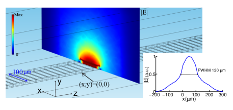
Figure S6 shows lateral mode shape of the antenna-feedback mode at approximately the longitudinal center of the cavity from 3D simulation. The SPP mode in surrounding medium extends in both lateral and vertical directions significantly, and the extent of the mode in lateral () dimension is greater than the width of the cavity itself. The FHWM of the mode shape along lateral () dimension of cavity at a distance of above top gratings (picked arbitrarily to keep it slightly away from location where finite-element mesh in simulation changes abruptly) is . This large effective wavefront created on top of the waveguide leads to a narrow far-field, i.e. a narrow “element-factor” in terminology of the radiation from a phased-array antenna. While the narrowing of “array-factor” due to constructive interference of radiation from all apertures in end-fire direction is also at play; it is not the dominant effect to cause narrow beaming for terahertz QCLs in this work for short-length cavities (). In contrast, for third-order DFB QCLs with phase-matching, beam narrowing is primarily due to the narrow array-factor only, which is why very long cavities () are needed to achieve beam divergence values of less than kao:dfbpm .
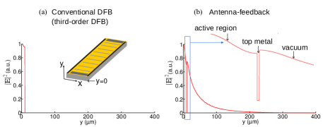
Figure S7 shows the electric-field squared modulus profile inside the cavity and above the metal cladding for both conventional DFB and antenna-feedback scheme from 2D simulations. Layer sequence follows active region with thickness, top metal layer with nm thickness (lossless metal) and air region. At the location above metal cladding, the mode-intensity in conventional DFB immediately decays to zero. In contrast, for antenna-feedback scheme, the sub-wavelength plasmonic resonant-optical mode inside the cavity is phased-locked with a SPP mode that travels on top of the metal cladding outside the cavity. The SPP wave is relatively tightly bound to the top metal cladding and decays in the length of the order of the wavelength in vacuum. The decay length is independent of the loss in metal or thickness in metal or various duty cycles of grating (which was verified via finite-element simulations). The establishment of a hybrid SPP mode on top of the cavity in vacuum is unique in antenna-feedback scheme. In a third-order DFB terahertz QCL, even with effective mode index getting close to , the feedback mechanism remains same as that in conventional DFB lasers, i.e. distributed-feedback couples propagating modes inside the cavity without involving the propagating SPP waves in the surrounding medium. Correspondingly, no standing SPP wave (with large amplitude) is established in the surrounding medium in a third-order DFB QCL’s cavity as it does in antenna-feedback scheme. This could be verified by simulating a terahertz QCL cavity structure with third-order DFB gratings, but with the refractive index of the active region arbitrarily set to a value of to satisfy the so-called “phase-matching” condition in simulation.