Berry phase of light Bragg-reflected by chiral liquid crystal media
Abstract
Berry phase is revealed for circularly polarized light when it is Bragg-reflected by a chiral liquid crystal medium of the same handedness. By using a chiral nematic layer we demonstrate that if the input plane of the layer is rotated with respect to a fixed reference frame, then, a geometric phase effect occurs for the circularly polarized light reflected by the periodic helical structure of the medium. Theory and numerical simulations are supported by an experimental observation, disclosing novel applications in the field of optical manipulation and fundamental optical phenomena.
pacs:
42.25.-p, 42.50.Tx,42.70.Df, 42.70.GiMarch 16, 2024
Berry phase is a phenomenon well known to occur when dealing with cyclic adiabatic transformations Berry (1984). Introduced by Berry for quantum systems undergoing a cyclic evolution under the action of a time-dependent Hamiltonian Berry (1984), the concept has been generalized to the accumulation of a geometrical phase arising from topological aspects in different quantum and classical systems, among the most known the Aharonov-Bohm effect and the precession of the oscillation plane of a Foucault pendulum (see, e.g., De Zela (2012) for a review). Berry phase for light is associated to geometric manipulation of the polarization and/or the direction of propagation, see Bliokh et al. (2008) and reference therein. Geometric phase due to the polarization state manipulation was discovered by the pioneering work of Pancharatnam, who highlight it as an intrinsic properties of polarized light Pancharatnam (1956). Indeed, when the polarization of a beam describes a closed-loop on the Poincaré sphere, the final state differs from the initial one by a geometric phase, Pancharatnam-Berry (PB) phase, proportional to the area enclosed by the loop. Based on this feature, space-variant waveplates have been specifically designed to realize PB phase optical elements with subwavelenght gratings, such as polarization sensitive diffraction gratings Bomzon et al. (2002) and spiral phase elements Biener et al. (2002), for laser radiation at wavelength. PB phase optical elements in the visible spectral domain have, then, been achieved by using nematic liquid crystals with patterned alignment, such as q-plates that generate helical modes of visible light Marrucci et al. (2006a); Nersisyan et al. (2013). Based on nematics, other PB phase optical devices, such as switchable lenses, beam splitters, and holographic elements, have been proposed Marrucci et al. (2006b) and, more recently, a diffractive lens with convergent/divergent behavior depending on the left/right handedness of the circular polarization of the input light has been realized Kim et al. (2015); Tam et al. (2015).
Here, we demonstrate that a Berry phase effect occurs for circularly polarized light when it is Bragg-reflected by a chiral liquid crystal medium. The optical wavelength and polarization handedness of the incident beam match, respectively, the Bragg wavelength and the handedness of the helical structure in the chiral medium. The geometric phase is introduced by the symmetry breaking in spin/momentum (handedness/direction) space and can be revealed by a space-variant optical axis of the uniaxial chiral layer. At the purpose of revealing the effect we employ a chiral nematic liquid crystal (CLC) cell with appropriately designed anchoring conditions at the entrance plane. Unlike conventional reflective elements, the meaningful component of the phase, here, is not introduced by optical path differences, but it results from the geometrical phase accumulated at the input plane of the CLC cell. Indeed, if at the input plane the CLC layer is rotated with respect to a fixed reference frame, then, a geometric phase effect occurs during the reflection. By exploiting this property, and by introducing patterns of molecular anchoring at the entrance plane of the CLC cell, reflectors performing different wavefront shaping can be designed and realized.
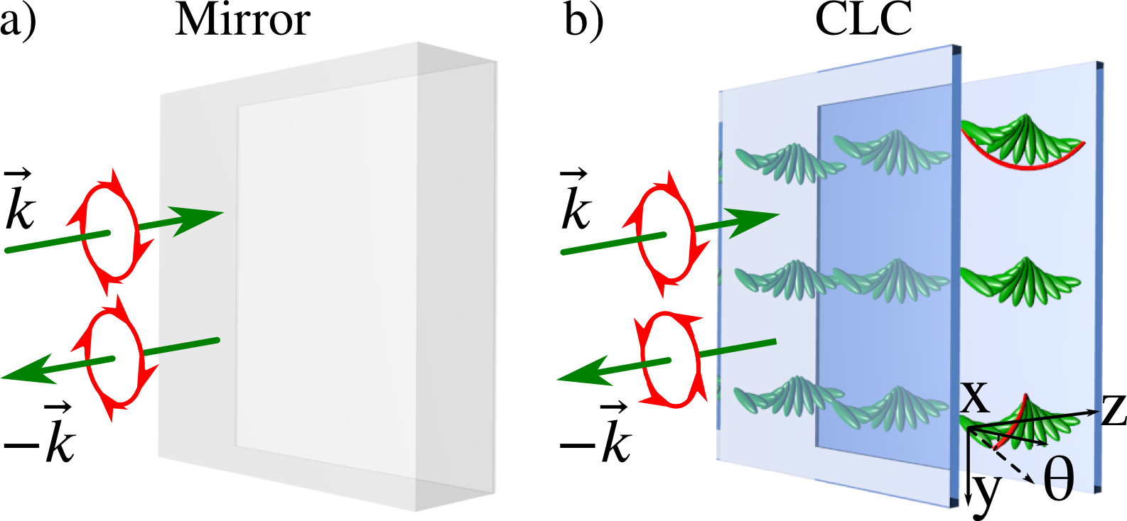
A qualitative comparison between a conventional mirror and a CLC medium is sketched in Fig. 1. At variance with the mirror (Fig. 1a), that reverses both the propagation direction and the polarization of the reflected light, the CLC cell (Fig. 1b) maintains the same polarization of the reflected beam. Indeed, CLC are characterized by a self-assembled helical structure of their molecular arrangement and selective Bragg reflection: when light is circularly polarized with the same handedness of the chiral helix, the periodic helical structure leads to Bragg reflection at normal incidence whenever the optical wavelength satisfies the condition , where is the chiral pitch and are the ordinary and extraordinary refractive indices, respectively de Gennes and Prost (1995). The circularly polarized component with opposite handedness is transmitted through the chiral layer. These properties combined with the ability to change their pitch with electric or magnetic fields Yeh and Gu (1999), with temperature Tzeng et al. (2010) or light Wei et al. (2012), make CLC attractive for applications as dynamically controlled reflection/transmssion filters Mitov and Dessaud (2006), tunable lasers Coles and Morris (2010) and photoswitchable bandgaps Hrozhyk et al. (2010). Here, we show that a Berry phase is always associated with the Bragg reflection at normal incidence, which allows adding novel functionalities to CLC layers, such as the ability to arbitrarily shaping the reflected wavefront.
I Detailed explanation
A detailed explanation of such geometric phase can be derived by considering a perfectly plane CLC layer with the director at its front face orientated at an angle with respect to the -axis of a fixed reference frame , coinciding with the axis of the chiral helix and with the propagation direction of the incident beam. We can now introduce a local coordinate system , such that is parallel to the molecular director at the input face of the CLC cell, that is, , and . In the fixed reference frame a -handed circular polarization writes as , which, in the local coordinate system, transforms to . Consider now a circularly polarized incident plane wave , with its wavelength inside the reflective bandgap of the CLC, its polarization handedness matching that of the chiral helix and at normal incidence. The incident wave is totally reflected by the CLC layer and its handedness is conserved after the reflection. In the fixed reference frame the reflected wave can, thus, be written as . If the axis of the CLC layer is chosen to coincide with (), then, we can apply the well known relation , with the reflection coefficient Yeh and Gu (1999). However, if the CLC is rotated by an angle with respect to , then, the relation between the amplitude of the incident and the reflected electric field must be considered in the local coordinate system and the phase arising from the coordinate transform from the local to the fixed reference must be taken into account, they do not necessarily cancel out. Therefore, the incident and the reflected beam, respectively, and in the local coordinate system write as and , respectively. The explicit dependence on and are dropped in sake of clarity. As a consequence, the reflection coefficient is given by , which can also be written as where is the Berry phase, the reflection coefficient in the local coordinate and does not depend on . Note that has a pure geometric origin, that is, it does not originate from an extra optical path but from a purely geometrical transformation, namely, the flipping of the propagation direction while maintaining the same helicity of the circular polarization, and the rigid rotation of the CLC layer. Based on the same analysis it is easy to show that the net geometric phase effect is cancelled for the transmitted component (case of thin layers). Indeed, in such case the amplitude of the transmitted wave can be written as , which transforms in the local coordinate system as the incindent beam, i.e. , and, correspondingly, the transmission coefficient , thus , being the transmission coefficient in the local reference, independent from .
The dependence of the reflection coefficient on the molecular angle at the input plane of the CLC layer can be derived analytically from the light propagation equations and by using the coupled mode theory. Such treatment can be found in the Supplemental Material Sup . As a result, all the possible cases can be simply summarized in a scattering matrix, which reads as
| (1) |
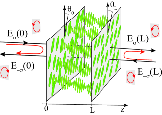
where is a -handed circularly polarized wave incident on the front face of the CLC layer and is a circularly polarized wave with the same handedness but propagating in the opposite direction and incident on the end face of the CLC layer. The output fields and are built each by two contributions: the beam transmitted through the CLC layer from the other end of the cell and the beam propagating from the same side and Bragg-reflected by the periodic helix in the CLC layer. From the scattering matrix terms it can be seen that the reflection coefficients are accompanied by a geometric phase, respectively and , where the angles and denote the anchoring direction of the molecules at the entrance, respectively, exit plane of the CLC layer. The derived scattering matrix is similar to those used to describe transmissive and reflective anistropic uniaxial geometric-phase element, see Bliokh K. Y. et al. (2015) and references therein. Rather than linking the reflected light or the transmitted light to the incident field, it connects circularly polarized components of reflected and transmited waves to the forward an the backward propagating circularly polarized incident fields; the handness considered in that of the cholesteric cell. Morever, unlike for the untwisted structures, the phase of the off-diagonal terms (that carry the information about the geometric phase) can be made independent with dissimilar anchoring angle at the faces of the geometric phase element. A scheme representing the scattering processes is displayed in Fig. 2.
II Numerics
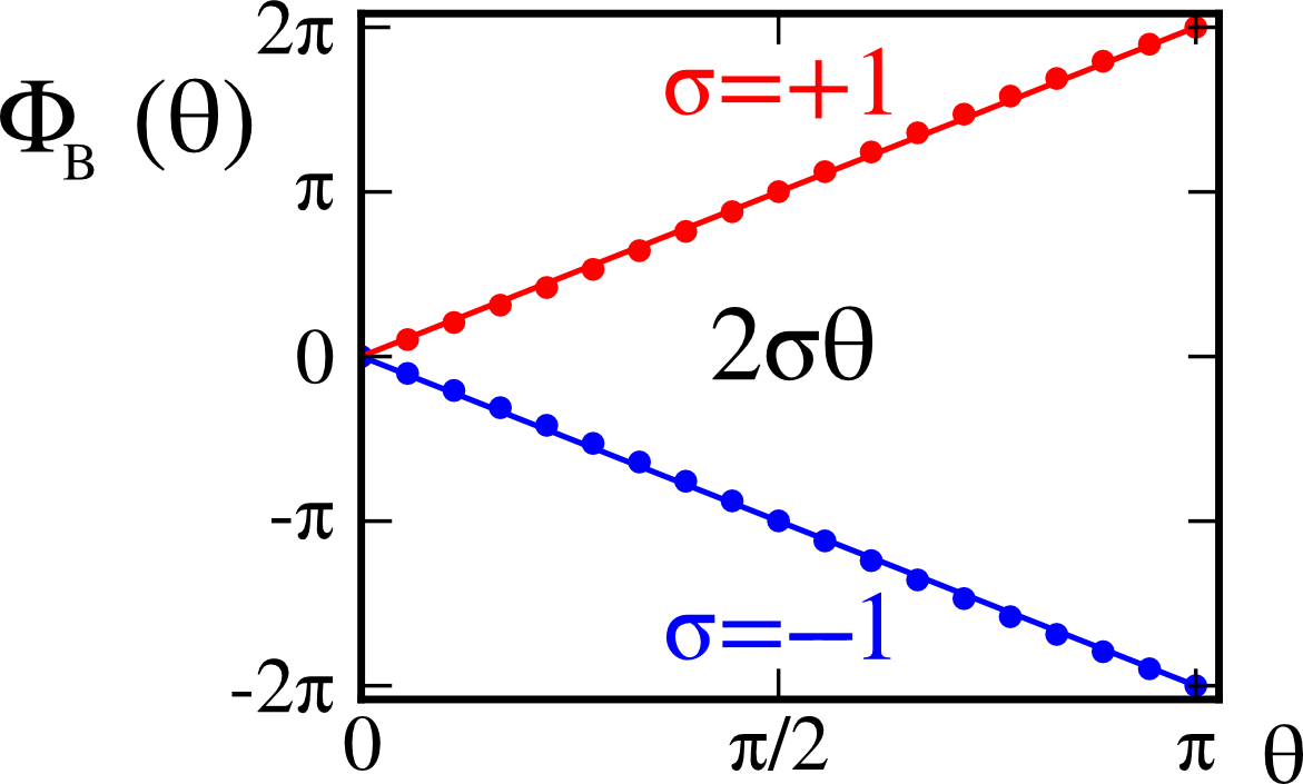
Numerical simulations were performed with the finite-difference time-domain (FDTD) method Taflove and Hagness (2005), using a freely available software package Oskooi et al. (2010). We have calculated the geometric phase, taking phase of the reflection coefficient of a left/right handed () circularly polarized beam by left/right handed helix Sup . The results are shown in Fig. 3, where is plotted versus the anchoring angle at the input of the cell. The right handed case and the left handed case were considered. The geometric phase varies linearly and the slope depends on the handedness of the polarization, can be clearly verified.
III Experiment
To reveal experimentally the effect we have setup a Michelson type interferometer in which one of the mirrors is substituted by a CLC cell, as depicted in Fig4. The cell is filled with a CLC mixture composed of the nematic E7 ( and at at ) doped with the chiral agent CB15 ( in weight). The chiral mixture is injected between two planar rubbed polyvinyl alcohol(PVA)-coated glass plates with thick spacers. The front plane of the cell has been rubbed mechanically in two step. After rubbing the first half of the glass plate, the second half is rubbed in a direction orthogonal to the previous one. This provides us with with two regions of orthogonal planar alignment, the anchoring angle being and in each region, respectively. The helical structure of the chiral mixture is perpendicular to the confining walls and has a pitch such that half-pitches are contained along the cell thickness. Note that the cell can be considered thick insofar as just a few pitches of the helix close to the entrance plane are enough to provide the total construction of the Bragg-reflected beam. The incident beam is circularly polarized with the same handedness of the chiral layer and overlaps the two regions of orthogonal anchoring. Because of the orthogonal anchoring conditions, the two regions of the CLC cell induce a geometric phase shift on the reflected wavefront. The phase shift is revealed by interfering the probe with the reference wave, which is reflected by an ordinary mirror. A quarter-wave plate is used to convert the probe to a circularly polarized wave with the same handedness as the CLC helix. Another quarter-wave plate is inserted in the reference arm in order to maximize the visibility of the fringes in the interference pattern, which is recorded by a CCD camera (cf. Fig. 4).
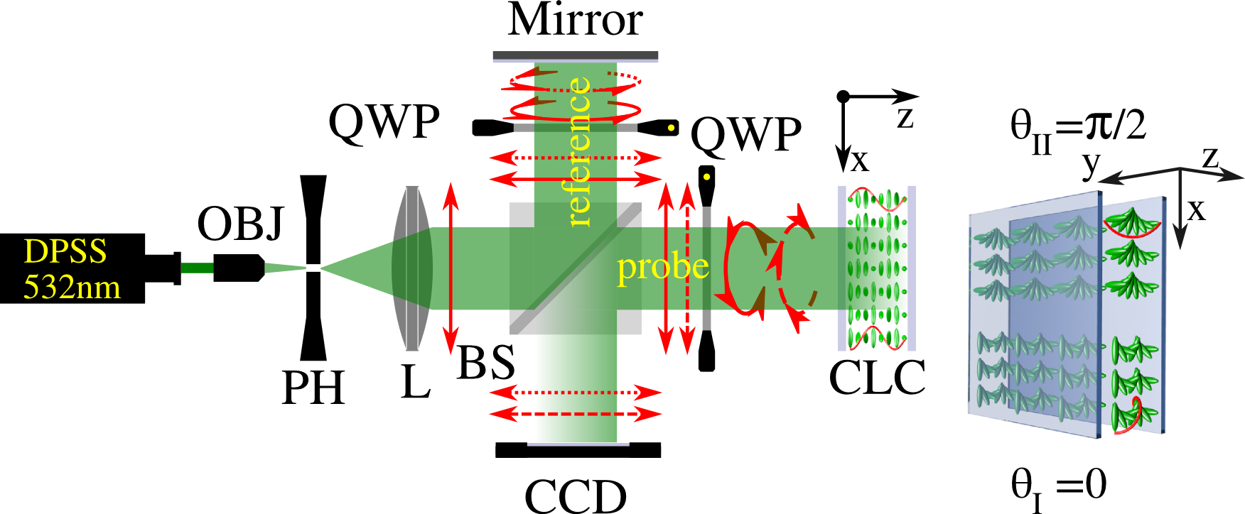
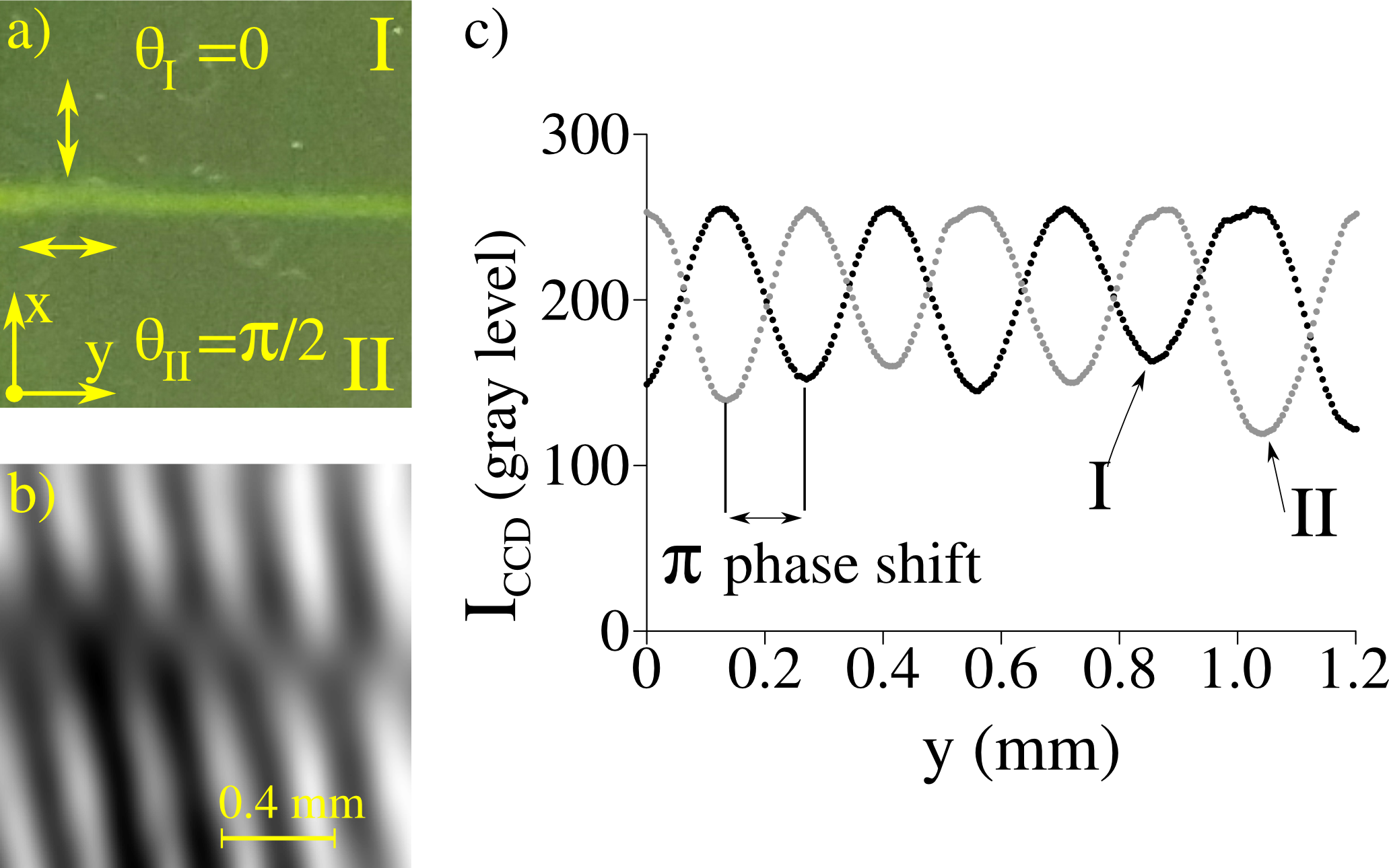
Figure 5a displays an instantaneous snapshot of the CLC cell, showing the interface between regions I and II. An experimentally recorded interference pattern is shown in Fig. 5b. Because the probe beam overlaps two regions with different orientation of the optical axis, a phase shift is expected to appear in the fringe interference pattern. Indeed, dislocation lines can clearly be distinguished across the interface, evidencing the phase difference between regions I and II, corresponding to , with and in this experiment. Figure 5c shows two one-dimensional intensity profiles taken on the fringe interference pattern in regions I and II, respectively. Again, the geometric phase shift can be clearly appreciated.
IV Conclusion
In conclusion, we have demonstrated that a Berry phase exists whenever circularly polarized light is Bragg-reflected by a CLC layer. Such geometrical phase originates from the orientation of the chiral layer at the entrance plane of the cell. Using more advanced alignment techniques based on photopolymers Chigrinov et al. (2008) and holographic Kim et al. (2015); Tam et al. (2015) recording or direct laser writting Miskiewicz and Escuti (2014); Kim et al. (2015), nearly arbitrary profile of planar anchoring can be achieved. Arbitrary profiles of geometric phase can then be achieved with application in complex wavefront shaping without the use of back reflectors. A very recent application was demonstrated by Kobayashi et al Kobashi Junji et al. (2016); but reference to geometric phase was not mentioned. Moreover, operation in different spectral regions could easily be achieved by changing the reflective bandgap of the CLC layer, and broadband devices could be obtainded Li et al. (2012) using the multitwisted layer architecture Komanduri et al. (2013).
Acknowledgements.
R. Barboza acknowledges FONDECYT POSTDOCTORADO 3140577 for the financial support. M.G. Clerc thanks the financial support of FONDECYT 1150507.References
- Berry (1984) M. V. Berry, Proceedings of the Royal Society of London A: Mathematical, Physical and Engineering Sciences 392, 45 (1984).
- De Zela (2012) F. De Zela, The Pancharatnam-Berry Phase: Theoretical and Experimental Aspects (InTech, 2012).
- Bliokh et al. (2008) K. Y. Bliokh, Y. Gorodetski, V. Kleiner, and E. Hasman, Phys. Rev. Lett. 101, 030404 (2008).
- Pancharatnam (1956) S. Pancharatnam, Proceedings of the Indian Academy of Sciences - Section A 44, 247 (1956).
- Bomzon et al. (2002) Z. Bomzon, G. Biener, V. Kleiner, and E. Hasman, Opt. Lett. 27, 1141 (2002).
- Biener et al. (2002) G. Biener, A. Niv, V. Kleiner, and E. Hasman, Opt. Lett. 27, 1875 (2002).
- Marrucci et al. (2006a) L. Marrucci, C. Manzo, and D. Paparo, Phys. Rev. Lett. 96, 163905 (2006a).
- Nersisyan et al. (2013) S. R. Nersisyan, N. V. Tabiryan, D. Mawet, and E. Serabyn, Opt. Express 21, 8205 (2013).
- Marrucci et al. (2006b) L. Marrucci, C. Manzo, and D. Paparo, Applied Physics Letters 88, 221102 (2006b).
- Kim et al. (2015) J. Kim, Y. Li, M. N. Miskiewicz, C. Oh, M. W. Kudenov, and M. J. Escuti, Optica 2, 958 (2015).
- Tam et al. (2015) A. M. W. Tam, F. Fan, H. S. Chen, D. Tao, V. Chigrinov, H. S. Kwok, and Y. S. Lin, SID Symposium Digest of Technical Papers 46, 8 (2015).
- de Gennes and Prost (1995) P. G. de Gennes and J. Prost, The Physics of Liquid Crystals, International Series of Monographs on Physics (Clarendon Press, 1995).
- Yeh and Gu (1999) P. Yeh and C. Gu, Optics of Liquid Crystal Displays, Wiley Series in Pure and Applied Optics (Wiley, 1999).
- Tzeng et al. (2010) S.-Y. Tzeng, C.-N. Chen, and Y. Tzeng, Liquid Crystals 37, 1221 (2010), http://dx.doi.org/10.1080/02678292.2010.492247 .
- Wei et al. (2012) D. Wei, A. Iljin, Z. Cai, S. Residori, and U. Bortolozzo, Opt. Lett. 37, 734 (2012).
- Mitov and Dessaud (2006) M. Mitov and N. Dessaud, Nat. Mater. 21, 361 (2006).
- Coles and Morris (2010) H. Coles and S. Morris, Nat. Photon. 4, 676 (2010).
- Hrozhyk et al. (2010) U. A. Hrozhyk, S. V. Serak, N. V. Tabiryan, T. J. White, and T. J. Bunning, Opt. Express 18, 9651 (2010).
- (19) The detailed derivation can be found in the Supplemental Material.
- Bliokh K. Y. et al. (2015) Bliokh K. Y., Rodriguez-Fortuno F. J., Nori F., and Zayats A. V., Nat Photon 9, 796 (2015).
- Taflove and Hagness (2005) A. Taflove and S. Hagness, Computational Electrodynamics: The Finite-difference Time-domain Method, 3rd ed., Artech House antennas and propagation library (Artech House, 2005).
- Oskooi et al. (2010) A. F. Oskooi, D. Roundy, M. Ibanescu, P. Bermel, J. D. Joannopoulos, and S. G. Johnson, Computer Physics Communications 181, 687 (2010).
- Chigrinov et al. (2008) V. G. Chigrinov, V. M. Kozenkov, and H.-S. Kwok, Photoalignment of Liquid Crystalline Materials: Physics and Applications (Wiley-SID Series in Display Technology, 2008).
- Miskiewicz and Escuti (2014) M. N. Miskiewicz and M. J. Escuti, Opt. Express 22, 12691 (2014).
- Kobashi Junji et al. (2016) Kobashi Junji, Yoshida Hiroyuki, and Ozaki Masanori, Nat Photon advance online publication (2016), http://dx.doi.org/10.1038/nphoton.2016.66 10.1038/nphoton.2016.66.
- Li et al. (2012) Y. Li, J. Kim, and M. J. Escuti, Proc. SPIE 8274, 827415 (2012).
- Komanduri et al. (2013) R. K. Komanduri, K. F. Lawler, and M. J. Escuti, Opt. Express 21, 404 (2013).