Energetic molding of chiral magnetic bubbles
Abstract
Topologically protected magnetic structures such as skyrmions and domain walls (DWs) have drawn a great deal of attention recently due to their thermal stability and potential for manipulation by spin current, which is the result of chiral magnetic configurations induced by the interfacial Dzyaloshinskii-Moriya Interaction (DMI). Designing devices that incorporate DMI necessitates a thorough understanding of how the interaction presents and can be measured. One approach is to measure growth asymmetry of chiral bubble domains in perpendicularly magnetized thin films, which has been described elsewhere by thermally activated DW motion. Here, we demonstrate that the anisotropic angular dependence of DW energy originating from the DMI is critical to understanding this behavior. Domains in Co/Ni multi-layers are observed to preferentially grow into non-elliptical teardrop shapes, which vary with the magnitude of an applied in-plane field. We model the domain profile using energetic calculations of equilibrium shape via the Wulff construction, which explains both the teardrop shape and the reversal of growth symmetry at large fields.
pacs:
75.70.Cn, 75.70.Kw, 65.40.gp,75.70.-iThe ability to manipulate chiral magnetic structures via the spin Hall effect has sparked renewed interest in spintronic devices that may lead to lower power, non-volatile memory and logic circuits.Bromberg et al. (2014); Emori et al. (2013); Fukami (2009); Parkin et al. (2008); Ryu et al. (2014) A key challenge is accurately measuring the Dzyaloshinskii-Moriya Interaction (DMI) and exploring interfaces that produce a larger net interfacial DMI in magnetic films to improve the efficiency by which novel spin configurations can be stabilized and manipulated with electric current. The DMI energy, , originates from the spin-orbit interaction and is analogous to the better known Heisenberg exchange interaction, .Dzyaloshinsky (1958); Moriya (1960) While Heisenberg exchange favors parallel or anti-parallel arrangement of neighboring spins, and , the DMI favors orthogonal alignment. For a polycrystalline thin film with inversion symmetry broken by dissimilar seed and capping layers, the DMI vector simplifies to according to Moriya’s rulesMoriya (1960); Thiaville et al. (2012), where is the unit vector connecting to and is along the film normal. This interfacial DMI, , explains the formation of skyrmions and novel spin textures in magnetic thin films that have canted spin structures.Bode et al. (2007); Heide et al. (2008); Heinze et al. (2011); Huang and Chien (2012); Jiang et al. (2015); Yu et al. (2010) Another consequence of interfacial DMI is the preference for formation of Néel domain walls (DWs) with preferred chirality over magnetostatically favored Bloch walls. In this context, the interfacial DMI is treated as a field, , acting perpendicular to the DW causing a rotation from Bloch to Néel type, where . Chen et al. (2013); Hrabec et al. (2014); Je et al. (2013)
The growth asymmetry of perpendicular chiral magnetic domains in the presence of an externally applied planar magnetic field, , was first suggested to originate from the DMI by Kabanov et al Kabanov et al. (2010) and later described in the context of creep DW motion using Co thin films grown on Pt.Hrabec et al. (2014); Je et al. (2013); Lavrijsen et al. (2015); Petit et al. (2015) The creep velocity is given by where is directly related to the energy of the DW, which will be a minimum (maximum) when is parallel (anti-parallel) to the applied field, . According to this model, the wall velocity, vs. , should be shifted for both the left and right sides of a magnetic bubble with a minimum occurring where cancels . However, it has frequently been observed that such a curve does not only shift, but also takes on an asymmetric shape. This has been attributed to dependence of DW width on applied field directionKim et al. (2016) although the magnitude of this effect is small. Another explanation is chiral damping, which has also been speculated to exist due to the spin-orbit interaction.Jue et al. (2016) While each of these factors could contribute to the asymmetric DW velocity, the role of the overall domain shape and angular dependence of wall energy have been largely ignored. Here, we perform experimental studies on chiral magnetic bubbles in Co/Ni multi-layers prepared on a Pt seedlayer to understand the evolution of the domain shape during growth. The unique shapes and anomalous growth symmetry observed experimentally are explained through equilibrium calculations based on minimization of domain wall energy using the Wulff construction.Herring (1951); Wulff (1901)
Films were prepared on Si(001) substrates with native oxide by DC magnetron sputtering from 5 inch targets in an Argon atmosphere fixed at 2.5mTorr unless otherwise noted. Base pressure was maintained at Torr. The film stack examined in this work is Si/TaN(3)/Pt(2.5)/[Co(0.2)/Ni(0.6)]2 /Co(0.2)/Ta(0.5)/TaN(3) with units in nm. The TaN layers were prepared by reactive sputtering in an Ar(2.5mTorr)/N2(0.5mTorr) gas mixture. M-H loops measured by alternating gradient field magnetometry(AGFM) and vibrating sample magnetometry (VSM) indicate = 600 kA/m, perpendicular mT, and in-plane T. From this, is calculated as m3. Films were confirmed to have FCC(111) fibre-texture by x-ray diffraction (XRD) as required for perpendicular magnetic anisotropy in most Co-based multi-layers.Kurt et al. (2010) The nucleation and growth of magnetic domains were observed using a white light, wide-field Kerr microscope. An electromagnet was used to apply in-plane fields while a perpendicular coil supplied short field pulses. Prior to observation, a focused Ga+ beam was used to damage a spot on the film with a dose of 1800 cm2 (at 5kV accelerating voltage) creating a nucleation site for magnetic bubble domains. Images were analyzed digitally to determine domain dimensions and normalized by the pulse length to determine average growth velocity. The dependence of growth velocity on in-plane field was performed by initially nucleating a magnetic domain of 10m diameter followed by perpendicular field pulses as indicated. For slow moving domain walls, multiple pulses were used to produce an appreciable displacement and it was observed that each subsequent pulse produced the same displacement.
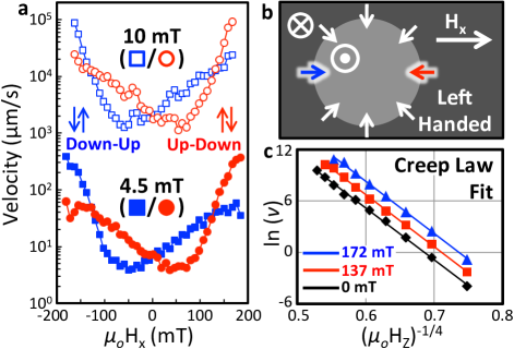
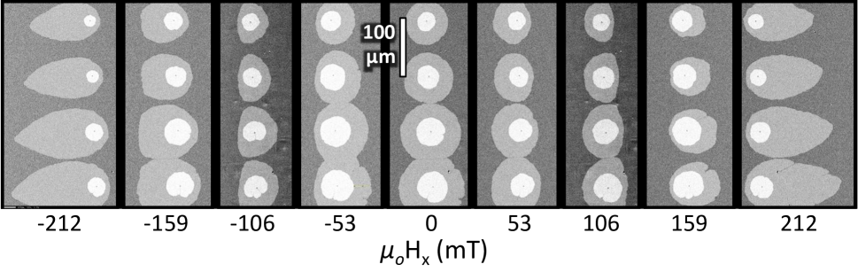
Figure 1 shows the domain wall velocity for the left (Down-Up) and right (Up-Down) side of a magnetic bubble as a function of applied field, , for 4.5 and 10mT. Also shown is the linear trends in ln(v) vs confirming creep behavior for all scenarios studied. While the velocity increased by more than two orders of magnitude for 10mT, the overall trend remains similar. A minimum in velocity occurs at positive for the Up-Down domain wall implying left-handed chirality (Figure 1b) according to the creep law, which is consistent with the sign of DMI measured and calculated elsewhere for Co/Pt interfaces.Hrabec et al. (2014); Je et al. (2013); Lavrijsen et al. (2015); Vaňatka et al. (2015); Yang et al. (2015) We also note that the curves are highly asymmetric about their minima resulting in a reversal of the preferred growth direction beyond some . If the chirality predicted according to the creep law at low fields is correct, this suggests that at large fields, the domain wall where is anti-parallel to displays a greater velocity; something that has not previously been reported. Moreover, the shape of the magnetic domain evolves with increasing as shown in Figure 2 for an array of four bubbles studied simultaneously. Most notably, for beyond the value at which the anomalous growth behavior is observed, the domain adopts a teardrop shape. We also note the formation of flattened shapes at lower .
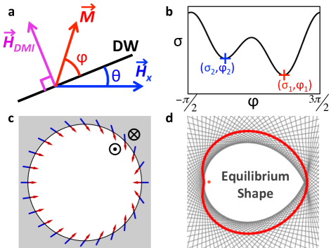
We now shift gears to better understand the origin of the anamolous growth symmetry in Figure 1 and the notable evolution of the domain shape as a function of applied field. The presence of cusps in the teardrop domains of Figure 2 show a striking resemblance to the facets and edges seen in bulk single crystals, which exist as a consequence of highly anisotropic interface energy. To address this in chiral bubbles, we consider the total free energy of the magnetic domain wall as a function of its orientation with respect to . The expression for DW energy is given by the following:Je et al. (2013); Pizzini et al. (2014)
| (1) |
Where and are defined in Figure 3a. is the Bloch wall energy and is the domain wall width. is the domain wall anisotropy energy that originates from the magnetostatic favorability to form Bloch walls in the absence of DMI. For a given value of , the equilibrium direction of magnetization is determined along with the corresponding energy, . Therefore, it is possible to produce an equilibrium polar energy plot as shown in Figure 3d (red), which is used to calculate the equilibrium shape via the Wulff construction.
The impact of and on equilibrium shape determined from the Wulff construction are outlined in Figure 4 using experimentally measured values of and . Here, we have assumed exchange stiffness, and domain wall anisotropy constant, .Yoshimura et al. (2016) However, for equilibrium shape calculations, it can be shown that the resulting shape is independent of and weakly dependent on for realistic values. It’s clear that as approaches , the equilibrium shape is pulled along one direction forming a high angle cusp as part of the teardrop shape.Boo This can be explained by the domain attempting to minimize the density of those walls that have anti-parallel to . While the Wulff construction does not calculate DW velocity directly, it does identify an anisotropic driving force for growth that is favored along the direction where the teardrop cusp is located. Moreover, we note that predicted from the velocity minimum in figure 1 of 60mT is significantly smaller than the values necessary to stabilize the teardrop shape based on our calculation.
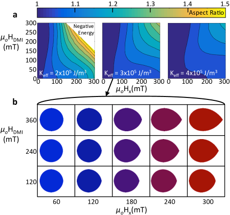

The teardrop shape has also been observed elsewhere in magnetic thin filmsHrabec et al. (2014); Lavrijsen et al. (2015); Woo et al. (2016), but no evidence has been presented to explain its origin or that suggests it coincides with a reversal in growth symmetry. We note, however, that the material parameters associated with Co/Ni multi-layers in our case deviate significantly from the Pt/Co bi-layers studied in these works. Specifically, the smaller in our films will decrease the resting Bloch wall energy while increasing the impact of Zeeman energy terms from and via increasing . One additional consequence of small is that negative wall energies are realized for the field values under consideration here. This suggests an instability of uniform perpendicular magnetization, which has been predicted to cause relaxation towards chiral spin textures or skyrmion lattices.Bogdanov et al. (2005); Rohart and Thiaville (2013); Pizzini et al. (2014) Such negative wall energies produce a wind in the polar free energy plot, which greatly complicates interpretation of the Wulff construction. The impact of on equilibrium shape is shown in the contour plots of Figure 4. Here, the aspect ratio, which originates primarily from the teardrop elongation, is plotted as a function of and . In all cases, this aspect ratio increases with increasing or , particularly when the two fields are comparable in magnitude. Most notably, as is reduced the aspect ratio increases for any combination of and . This could explain why the anomalous growth direction and teardrop shapes observed in this work have not been reported in comparable cases where is larger.
While the Wulff construction explains the formation of teardrop shapes at high field, it does not explain the flattened shape at low . In fact, it is counter to such a result as this shape increases the density of domain walls that have anti-parallel to the applied field. Instead, we demonstrate how this shape could be explained through a refinement of our calculation we call a pseudo-equilibrium Wulff construction. From Figure 3b, it is clear that for some values of , there can be two energy minima associated with appreciable DW anisotropy energy. In this approximation, we assume that the appearance of each variant will occur with equal probability. As such, we have repeated our Wulff construction so that the energy of a domain wall is given by the average energy of the two possible magnetization directions. If there is only a single energy minimum, then that value represents the equilibrium DW energy. The results of this construction are shown in Figure 5. It can be seen that for large and low , the flattening observed in experiment is reproduced. This occurs because stabilizes the DWs with multiple variants, which will have higher energy than those that do not. Therefore, the equilibrium bubble shape maximizes length for DWs that do not form metastable variants. For example, consider Figure 5b where the left arc is free of multiple variants while the right is not. As increases, the fraction of DWs that can support multiple variants shrinks along with the length of the flattened region. Beyond some value of , multiple variants are no longer supported or only supported for a narrow region on the right side of the bubble and the equilibrium construction is recovered.
However, the flattening is only observed for unrealistically large values of and, therefore, the situation requires a more complicated explanation. The formation of Bloch points in perpendicular Co/Ni multi-layers have been discussed in much detail elsewhere and are predicted to form in significant density where is anti-parallel to . Such Bloch points would increase the wall energy where stable and also serve as pinning sites during DW growth.Yoshimura et al. (2016) It is possible that the rapid transition from a flat growth front to a teardrop shape is related to the annihilation of Bloch points at a critical field that had been pinning the DW. Such a critical field would be directly related to the interfacial DMI vector although additional micromagnetic modeling is needed to quantitatively predict Bloch point density and determine the contribution to overall DW energy and growth dynamics.
In summary, we have presented a new paradigm for describing the behavior of chiral magnetic bubbles that is based on classical interface thermodynamics, which has been paramount in the broader field of phase transformations, but has not previously been applied in the context of chiral magnetism. We show that the non-elliptical teardrop morphology associated with growth of magnetic domains in structurally asymmetric Co/Ni thin films can be explained by a driving force towards the formation of equilibrium shapes. Furthermore, the appearance of teardrop domains coincides with a reversal of the growth symmetry expected from creep motion dynamics. Both the teardrop shape and the anomalous preferred growth direction is predicted from the Wulff construction and becomes most pronounced as approaches . Our study here demonstrates that the wall velocity obtained by static wall position measurements after motion is actually the combined effect of thermally activated creep driven by perpendicular magnetic fields and the energetic relaxation of the bubble domain towards its equilibrium shape during growth. This new driving force suggests that determined from the minimum in velocity underestimates the magnitude of the DMI vector, especially for low materials where the polar energy plots become highly anisotropic. This may explain discrepancies in growth asymmetry observed throughout the literature and inconsistencies between direct observations of wall chirality and those inferred from asymmetric bubble growth.
This work was partially supported by the Collaborative Innovation Research Center through The Joint Institute of Engineering at Sun Yat-Sen University, The Samsung Global MRAM Innovation Project, and the Berkman Faculty Development Fund.
References
- Bromberg et al. (2014) D. Bromberg, M. Moneck, V. Sokalski, J. Zhu, L. Pileggi, and J. G. Zhu, Electron Devices Meeting (IEDM), 2014 IEEE International , 33.1.1 (2014).
- Emori et al. (2013) S. Emori, U. Bauer, S.-M. Ahn, E. Martinez, and G. S. D. Beach, Nature Materials 12 (2013).
- Fukami (2009) S. Fukami, Digest of Technical Papers. Symposium on VLSI Technology. 12A-2 (2009).
- Parkin et al. (2008) S. S. P. Parkin, M. Hayashi, and L. Thomas, Science 320, 190 (2008).
- Ryu et al. (2014) K.-S. Ryu, S.-H. Yang, L. Thomas, and S. Parkin, Nature Communications (2014).
- Dzyaloshinsky (1958) I. Dzyaloshinsky, Journal of physics and chemistry of solids 4, 241 (1958).
- Moriya (1960) T. Moriya, Physical Review 120, 91 (1960).
- Thiaville et al. (2012) A. Thiaville, S. Rohart, E. Jue, V. Cros, and A. Fert, EPL 100 (2012).
- Bode et al. (2007) M. Bode, M. Heide, K. von Bergmann, P. Ferriani, S. Heinze, G. Bihlmayer, A. Kubetzka, O. Pietzsch, S. Blugel, and R. Wiesendanger, Nature 447, 190 (2007).
- Heide et al. (2008) M. Heide, G. Bihlmayer, and S. Blugel, Physical Review B 78 (2008).
- Heinze et al. (2011) S. Heinze, K. von Bergmann, M. Menzel, J. Brede, A. Kubetzka, R. Wiesendanger, G. Bihlmayer, and S. Blugel, Nature Physics 7, 713 (2011).
- Huang and Chien (2012) S. X. Huang and C. L. Chien, Physical Review Letters 108 (2012).
- Jiang et al. (2015) W. J. Jiang, P. Upadhyaya, W. Zhang, G. Q. Yu, M. B. Jungfleisch, F. Y. Fradin, J. E. Pearson, Y. Tserkovnyak, K. L. Wang, O. Heinonen, S. G. E. te Velthuis, and A. Hoffmann, Science 349, 283 (2015).
- Yu et al. (2010) X. Z. Yu, Y. Onose, N. Kanazawa, J. H. Park, J. H. Han, Y. Matsui, N. Nagaosa, and Y. Tokura, Nature 465, 901 (2010).
- Chen et al. (2013) G. Chen, T. P. Ma, A. T. N’Diaye, H. Kwon, C. Won, Y. Z. Wu, and A. K. Schmid, Nature Communications 4 (2013).
- Hrabec et al. (2014) A. Hrabec, N. A. Porter, A. Wells, M. J. Benitez, G. Burnell, S. McVitie, D. McGrouther, T. A. Moore, and C. H. Marrows, Physical Review B 90 (2014).
- Je et al. (2013) S.-G. Je, D.-H. Kim, S.-C. Yoo, B.-C. Min, K.-J. Lee, and S.-B. Choe, Physical Review B 88 (2013).
- Kabanov et al. (2010) Y. P. Kabanov, Y. L. Iunin, V. I. Nikitenko, A. J. Shapiro, R. D. Shull, L. Y. Zhu, and C. L. Chien, Ieee Transactions on Magnetics 46, 2220 (2010), 601dh Times Cited:2 Cited References Count:19.
- Lavrijsen et al. (2015) R. Lavrijsen, D. Hartmann, A. van den Brink, Y. Yin, B. Barcones, R. Duine, M. Verheijen, H. Swagten, and B. Koopmans, Physical Review B 91 (2015).
- Petit et al. (2015) D. Petit, P. Seem, M. Tillette, R. Mansell, and R. Cowburn, Applied Physics Letters 106 (2015).
- Kim et al. (2016) D.-Y. Kim, D.-H. Kim, and S.-B. Choe, Applied Physics Express 9, 053001 (2016).
- Jue et al. (2016) E. Jue, C. K. Safeer, M. Drouard, A. Lopez, P. Balint, L. Buda-Prejbeanu, O. Boulle, S. Auffret, A. Schuhl, A. Manchon, I. M. Miron, and G. Gaudin, Nature Materials 15, 272 (2016).
- Herring (1951) C. Herring, Physical Review 82, 87 (1951).
- Wulff (1901) G. Wulff, Zeitschrift Fur Krystallographie Und Mineralogie 34, 449 (1901).
- Kurt et al. (2010) H. Kurt, M. Venkatesan, and J. M. D. Coey, Journal of Applied Physics 108 (2010).
- Vaňatka et al. (2015) M. Vaňatka, J.-C. Rojas-Sánchez, J. Vogel, M. Bonfim, M. Belmeguenai, Y. Roussigné, A. Stashkevich, A. Thiaville, and S. Pizzini, Journal of Physics: Condensed Matter 27, 326002 (2015).
- Yang et al. (2015) H. Yang, A. Thiaville, S. Rohart, A. Fert, and M. Chshiev, Phys. Rev. Lett. 115, 267210 (2015).
- Pizzini et al. (2014) S. Pizzini, J. Vogel, S. Rohart, L. D. Buda-Prejbeanu, E. Jue, O. Boulle, I. M. Miron, C. K. Safeer, S. Auffret, G. Gaudin, and A. Thiaville, Physical Review Letters 113 (2014).
- Yoshimura et al. (2016) Y. Yoshimura, K. J. Kim, T. Taniguchi, T. Tono, K. Ueda, R. Hiramatsu, T. Moriyama, K. Yamada, Y. Nakatani, and T. Ono, Nature Physics 12, 157 (2016).
- (30) It is interesting to note that similar, but unrelated equilibrium shapes have been observed and predicted elsewhere based on the Wulff construction in monolayer domains of chiral liquid crystals associated with 2D Boojum structures.Fang et al. (1997); Rudnick and Bruinsma (1995).
- Woo et al. (2016) S. Woo, K. Litzius, B. Kruger, M.-Y. Im, L. Caretta, K. Richter, M. Mann, A. Krone, R. M. Reeve, M. Weigand, P. Agrawal, I. Lemesh, M.-A. Mawass, P. Fischer, M. Klaui, and G. S. D. Beach, Nature Materials (2016).
- Bogdanov et al. (2005) A. N. Bogdanov, U. K. Rossler, and C. Pfleiderer, Physica B-Condensed Matter 359, 1162 (2005).
- Rohart and Thiaville (2013) S. Rohart and A. Thiaville, Physical Review B 88 (2013).
- Fang et al. (1997) J. Y. Fang, E. Teer, C. M. Knobler, K. K. Loh, and J. Rudnick, Physical Review E 56, 1859 (1997).
- Rudnick and Bruinsma (1995) J. Rudnick and R. Bruinsma, Physical Review Letters 74, 2491 (1995).