Interfacial Dzyaloshinskii-Moriya interaction in Pt/CoFeB films: effect of the heavy-metal thickness
Abstract
We report the observation of a Pt layer thickness dependence on the induced interfacial Dzyaloshinskii-Moriya interaction in ultra-thin Pt()/CoFeB films. Taking advantage of the large spin-orbit coupling of the heavy metal, the interfacial Dzyaloshinskii-Moriya interaction is quantified by Brillouin light scattering measurements of the frequency non-reciprocity of spin-waves in the ferromagnet. The magnitude of the induced Dzyaloshinskii-Moriya coupling is found to saturate to a value mJm2 for Pt thicknesses larger than nm. The experimental results are explained by analytical calculations based on the 3-site indirect exchange mechanism that predicts a Dzyaloshinskii-Moriya interaction at the interface between a ferromagnetic thin layer and a heavy metal. Our findings open up a way to control and optimize chiral effects in ferromagnetic thin films through the thickness of the heavy metal layer.
In the last few years the Dzyaloshinskii-Moriya interaction (DMI) Dzyaloshinskii ; Moriya , i.e. the antisymmetric exchange interaction, has been the subject of intense research due to its capability to induce the formation of chiral spin textures, such as magnetic skyrmion lattices Bogdanov ; Muhlbauer ; Munzer ; Yu ; Yu11 ; Heinze ; Onose ; Nagaosa ; Fert13 and spin spirals Uchida ; Bode ; Ferriani . In ultrathin ferromagnetic (FM) films in contact with a nonmagnetic heavy-metal (HM), a noticeable interfacial DMI can arise due to the large spin-orbit coupling (SOC) in the presence of the broken inversion symmetry at the FM/HM interface Bode ; Fert13 , leading for instance to asymmetric spin-wave dispersion Zakeri . Interfacial DMI in FM/HM bilayers is usually stronger than bulk DMI in non-centrosymmetric chiral magnets Iguchi ; Seki , which also has the advantage of room temperature operation using conventional magnetic materials. In such structures, the combination of the interfacial DMI, which stabilizes chiral Nel domain walls (DW), and of the Spin-Hall effect Liu ; Sinova has been found to enable a surprisingly fast current-driven DW motion Heide ; Moore ; Thiaville ; ChenPRL ; Emori ; Boulle ; Brataas ; Torrejon . It has also been observed that both the velocity and the direction of the DW motion depend on the DMI strength and can be controlled by engineering the interface between the two materials Torrejon ; Ryu ; Chen . From a technological point of view, these structures are of great importance, due to their enormous potential for current-controlled DW motion for the development of novel memory-storage devices with high density and performance in so-called racetrack memories Parkin . A deeper understanding of the interfacial DMI mechanism in such structures and a precise estimation of its magnitude, are therefore crucial for tailoring efficient spintronics devices.
Early measurements of the strength of the DMI were reported using spin-polarized scanning tunneling microscopy Bode , highly resolved spin-polarized electron energy loss spectroscopy Zakeri , and synchrotron based X-ray scattering Dmitrienko . More recently, Brillouin light scattering (BLS) has proven to be a powerful technique to study interfacial DMI in a variety of FM/HM systems DiPRL ; Zhang ; DiAPL ; Cho ; Nembach ; Stashkevich ; Belmeguenai such as shown in Fig. 1. BLS experiments on ultrathin FM/HM bilayers have shown that interfacial DMI induces a significant asymmetry in the frequency dispersion of the counter-propagating Damon-Eshbach (DE) spin-wave (SW) modes, as theoretically predicted in Refs. Kataoka ; Udvardi ; Costa ; Cortes ; Moon , which makes direct measurements of the strength of the induced DMI possible. Moreover, the effect of the interfacial DMI has been investigated in wedge-shaped samples Cho , and also in structures where the thickness of the FM layer is varied Nembach ; Stashkevich ; Belmeguenai , demonstrating a behavior of the strength of the interaction, which is direct consequence of the surface nature of such coupling. This phenomenology was also found through all-electrical measurements in Pt/Co/MgO samples Lee . Interestingly, the discussion related to the role and importance of Pt thickness is devoid in all those experiments. More recently Yang et al. performed first principles calculations of DMI in Co/Pt where its strength is featured for specific spin configurations and up to three Co and Pt atomic layers, founding a weak contribution from Pt thickness Yang .
In this work we study the influence of the heavy metal thickness on the interfacial DMI. Using BLS measurements on ultrathin CoFeB films in contact with a Pt layer with variable thickness (), we found that the strength of the interfacial DMI increases with Pt thickness, reaching a saturation value for larger than a few nanometers. We are able to explain our experimental results using the -site DMI introduced by Levy and Fert Levy69 ; Smith ; Fert , where the asymmetric exchange interaction between two neighboring FM atoms is mediated by a third non-magnetic atom, Pt in this case, having a large SOC. Here we show that the evolution of interfacial DMI as a function of the Pt thickness, can be understood assuming that hopping electrons can scatter with Pt sites belonging to several layers in the HM.
We studied a series of samples consisting of Si-SiO2/Co40Fe40B20(2 nm)/Pt()/Cu(3 nm) where was changed in the range between 0 and 6 nm. The samples were grown by magnetron sputtering on thermally oxidized Si substrates. The base pressure of the chamber was Torr, and the deposition times were calculated using calibrated growth rates. The saturation magnetization was determined from hysteresis curves measured by a MicroMag alternating gradient magnetometer (AGM). BLS measurements were performed focusing about mW of monochromatic light from a solid state laser operating at nm onto the sample surface. The back-scattered light was analyzed by a Sandercock-type ()-pass tandem Fabry-Perot interferometer BLS . A bias field kOe was applied parallel to the surface plane, while the in-plane wave vector was swept along the perpendicular direction (DE configuration). Due to the photon-magnon conservation law of momentum in the scattering process, the amplitude of the in-plane wave vector is linked to the incidence angle of light by . In our measurements was changed from 0 to rad/m.
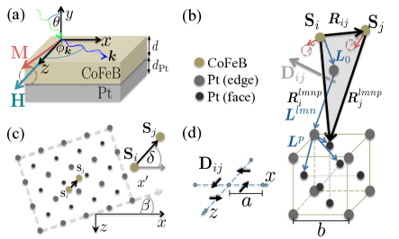
In order to analyze the experimental results we start with the usual Hamiltonian ascribed to the interfacial DMI, , which couples neighboring atomic spins and in the interfacial layer of the CoFeB film through a third Pt site 111This type of interfacial DMI is similar to the one that should appears in non-centrosymmetric crystals of class Cortes , where the interaction is between two FM atomic spins with spin-orbit on the FM site Moriya .. The DMI in FM/HM bilayers is usually described using a formalism developed for disordered magnetic alloys with HM impurities Fert ; Prejean . Here, an additional contribution to the Ruderman-Kittel-Kasuya-Yosida interaction appears, which is of Dzyaloshinskii-Moriya type and arises from the SOC of the conduction electron gas with non-magnetic impurities Fert . The DM vector links FM spins at sites and with a third Pt site in the HM Fert and is perpendicular to the triangle described by the three sites. It is well known that the DMI becomes particularly relevant at the interface between a ultrathin FM film and a HM with strong SOC. This fact, together with the BLS data presented here, suggests that several Pt atoms may contribute to the strength of the interfacial DMI. Hence, in order to evaluate the DM vector, one have to consider the thickness and lattice structure of the HM, in such a way that the electrons can scatter with several Pt sites close to a pair of FM spins, and thus build up the effective interfacial DMI. Then, the DM vector Fert ; Crepieux associated with and , must include contributions from more than one Pt atom, and can be generally estimated from
| (1) |
where is a factor proportional to the SOC constant and other parameters of the HM SuppMat . The sum is over Pt lattice sites that are neighbors with and . As it is displayed in Fig. 1, the vectors , and , join and to the fcc lattice sites of Pt. Vector joins FM site with the closest Pt atom labeled with , while vector runs from the (000) Pt site to the neighbors cubic sites at the edges of a fcc lattice, labeled by (), where and , with and running through a few lattice sites, corresponding to a distances of the order of the spin diffusion length. Vector describes the position of the 4 Pt atoms associated to site (): , , , and . CoFeB atoms are assumed in the film plane then where is the angle between and the axis, while is the average separation of nearest neighbors spins. The index is introduced to consider first, second or even third neighbors SuppMat . With this model, we get for the DM vector between spins at and , , and between spins at and [see Fig. 1(d)], where the component of cancels out SuppMat .
In the micromagnetic limit the DM Hamiltonian is determined SuppMat by assuming that the magnetization does not depend on the normal coordinate, due to the ultrathin thickness of the ferromagnetic film. On this basis, the frequency dispersion of the spin waves is computed and it turns out to be separated into two contributions, , with , where is the volume averaged DMI strength. The symmetric part, , is composed by the exchange, dipolar, anisotropy, and Zeeman contributions Cortes . Here, is the gyromagnetic ratio, and the angle between and the plane SuppMat . Then, the frequency difference between oppositely propagating spin-waves is , and its dependency with the FM and HM layers reads 222In the case of bulk DMI, as those encountered in B20 crystals, a similar spin-wave theory Cortes have shown that , which has been measured recently in chiral magnets Cu2OSeO3 Seki and LiFe5O8 Iguchi .
| (2) |
where measures the strength of the interfacial DMI averaged over the volume of the FM film. According to Nembach et al. Nembach it is related to the DMI strength at the interface , where is the number of FM atomic layers. By measuring through BLS the DMI strength has been found in several materials, whose highest value of 2.7 mJ/m2 was reported in Pt(3)/Co(0.6)/AlOx samples Belmeguenai .
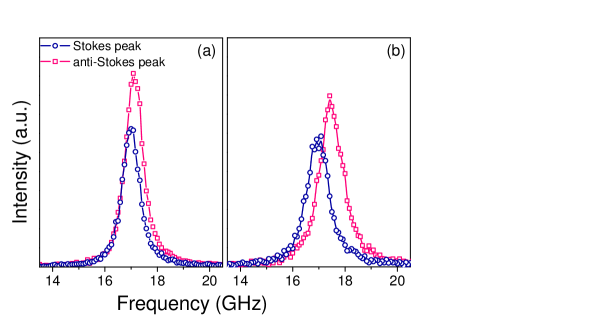
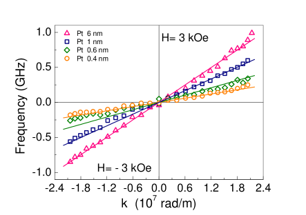
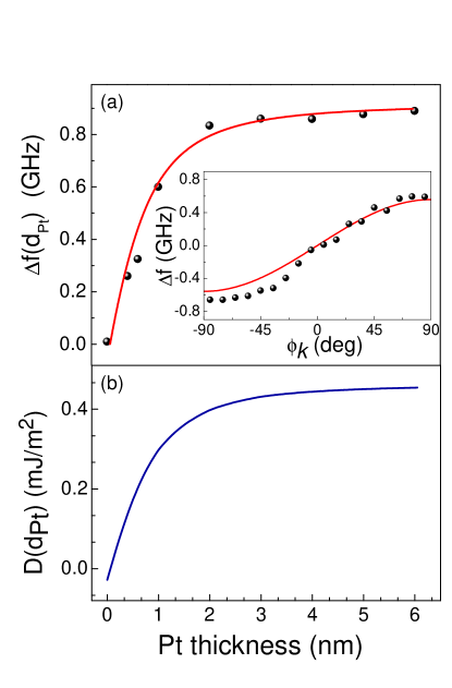
Typical BLS spectra measured for samples having a Pt thickness of nm and nm are shown in Fig. 2(a) and 2(b), respectively. Due to the small sample thickness, both the Stokes and anti-Stokes peaks, corresponding to SWs propagating in opposite directions are simultaneously observed with comparable intensity. As it can be seen, the Stokes and anti-Stokes peaks are characterized by a frequency shift which increases with Pt thickness. Moreover, the frequency of both peaks interchanges on reversing the direction of the applied magnetic field, due to the reversal of the SWs propagation direction. Fig. 3 shows the frequency difference between the Stokes and the anti-Stokes peaks measured (points) as a function of the wave vector k. In agreement with Eq. (2) we found that the frequency asymmetry exhibits a linear dependence as a function of k, and it becomes more pronounced when increasing the Pt thickness. To better understand the effect of the platinum thickness, the frequency shift measured at rad/m is reported in Fig. 4(a) as a function of . One can see that the frequency difference increases linearly with , reaching a saturation value at about nm. A fit procedure SuppMat of the experimental data to the theoretical model was performed using Eq. (2). In this analysis, we consider for amorphous CoFeB nm Kirk , and for the fcc lattice parameter of Pt nm Kittel , while the atomic spacer between the CoFeB and the Pt layers, was set to the mean value between and , nm. On the basis of the AGM measurements, we assumed T for samples having a Pt thickness larger than 1 nm, while for samples with lower than 1 nm, decreases until 1.22 T.
A good agreement with the experiments is obtained by setting , , and the fitting parameters GHz, and the average spatial range of DMI nm, which for nm gives SuppMat . The fit is shown by the continuous curves in Fig. 3 for the linear behavior with and Fig. 4(a) for the thickness dependence, where the solid red curve is a linear interpolation. The measured angular dependence of the frequency shift, see inset of Fig. 4(a), was obtained for a thickness nm at a wave vector rad/m, showing a clear sine like dependence Cho ; Cortes ; Zhang in agreement with Eq. 2. The strength of the interfacial DMI obtained from the fit is reported in Fig. 4(b). As it can be seen grows with the Pt thickness and reaches a saturation value of almost 0.45 mJ/m2 at about four Pt monolayers ( nm). This characteristic can be traced back to the spin transport parameter, the so-called spin-diffusion length. As we pointed out, interfacial DMI originates from the indirect exchange between FM spins and neighboring HM atoms having a large SOC. Such SOC in Pt is responsible for the loss of spin information carried by electrons after a characteristic spatial range given by the spin-diffusion length, which at room temperature takes values in the range of nm Liu ; Obstbaum ; WZhang ; Isasa . Therefore, the spin-diffusion length spatially limits the indirect exchange mechanism that induces the DMI and accordingly, its enhancement with Pt thickness.
It is important to note that the average spatial range of the interfacial DM coupling , is almost three times larger than the average interatomic distance nm Kirk . This can be understood taking into account the fact that the interfacial DMI is an indirect exchange coupling between FM atomic spins mediated by conduction electrons that populates the structure. As a consequence two interacting spins may communicate via DMI even if they are next nearest-neighbors. This can be verified by noting that in the present case of a saturated in-plane magnetization, the only important DMI is between the dynamic magnetization components. Indeed, a simple evaluation of the DMI energy between spins and leads to where is the dynamical component of the -th spin.
Therefore, for typical wave vectors ( radm) the DM coupling turns out to be relevant not only for first nearest neighbor precessing spins but it covers a couple of atomic sites of the CoFeB. Similar considerations that involve the interaction of pair of spins beyond first neighbors has also been mentioned in Ref. Yang , where the authors argued that second neighbors do not significantly contribute to the effective DMI, while direct exchange was considered up to seventh neighbors 333 As it can be seen, goes rapidly to zero when , indicating that interfacial DMI is significant up to the third neighbor spins, while its role becomes negligible for farther away spins..
In summary, non-reciprocity of the spin-wave spectra in Pt()/CoFeB ultrathin films was studied by Brillouin spectroscopy for different Pt thicknesses. The BLS spectra of Stokes and anti-Stokes peaks establishes a linear relation between the asymmetry in the SWs frequency and the wave vector. We observed, and theoretically demonstrated by virtue of the 3-site indirect exchange mechanism Fert , an increasing interfacial DMI as the Pt thickness increases. We propose that the mechanism behind the observed DMI enhancement with , consists of cumulative electron hopping between the atomic spins at the interface and the non-magnetic atoms in the heavy metal. Nevertheless, for a given thickness of the CoFeB layer, the DMI magnitude does not exceed the saturation value mJm2 for Pt thicknesses larger than the spin-diffusion length nm Isasa . Thickness-dependent DMI studies will offer a great prospect in the fields of spintronics and magnonics, in order to induce and spatially control chiral effects in magnetic materials.
We acknowledge financial support from the Göran Gustafsson Foundation, the Swedish Research Council (VR), Energimyndigheten (STEM), the Knut and Alice Wallenberg Foundation (KAW), the Carl Tryggers Foundation (CTS), and the Swedish Foundation for Strategic Research (SSF). This work was also supported by the European Research Council (ERC) under the European Community’s Seventh Framework Programme (FP/2007-2013)/ERC Grant 307144 "MUSTANG", by FONDECYT (Chile) grants 3150372 and 1161403, and Centers of excellence with Basal/CONICYT financing, grant FB0807, CEDENNA.
References
- (1) I. Dzyaloshinskii, Sov. Phys. JETP 5 1259 (1957).
- (2) T. Moriya, Phys. Rev. Lett. 4, 228 (1960); T. Moriya, Phys. Rev. 120, 91 (1960).
- (3) A. N. Bogdanov and D. A. Yablonskii, Sov. Phys. JETP 68, 101 (1989); A. N. Bogdanov and U. K. Rößler, Phys. Rev. Lett. 87, 037203 (2001); U. K. Rößler, A. N. Bogdanov, and C. Pfleiderer, Nature 442, 797 (2006).
- (4) S. Mühlbauer, B. Binz, F. Jonietz, C. Pfleiderer, A. Rosch, A. Neubauer, R. Georgii, and P. Böni, Science 323, 915 (2009).
- (5) W. Münzer, A. Neubauer, T. Adams, S. Mühlbauer, C. Franz, F. Jonietz, R. Georgii, P. Böni, B. Pedersen, M. Schmidt, A. Rosch, and C. Pfleiderer, Phys. Rev. B 81, 041203(R) (2010).
- (6) X. Z. Yu, Y. Onose, N. Kanazawa, J. H. Park, J. H. Han, Y. Matsui, N. Nagaosa, and Y. Tokura, Nature 465, 901 (2010).
- (7) X. Z. Yu, N. Kanazawa, Y. Onose, K. Kimoto, W. Z. Zhang, S. Ishiwata, Y. Matsui, and Y. Tokura, Nat. Mater. 10, 106 (2011).
- (8) S. Heinze, K. von Bergmann, M. Menzel, J. Brede, A. Kubetzka, R. Wiesendanger, G. Bihlmayer, and S. Blügel, Nat. Phys. 7, 713 (2011).
- (9) Y. Onose, Y. Okamura, S. Seki, S. Ishiwata, and Y. Tokura, Phys. Rev. Lett. 109, 037603 (2012).
- (10) N. Nagaosa and Y. Tokura, Nat. Nanotech. 8, 899 (2013).
- (11) A. Fert, V. Cros, and J. Sampaio, Nat. Nanotech. 8, 152 (2013)
- (12) M. Uchida, Y. Onose, Y. Matsui, and Y. Tokura, Science 311, 359 (2006).
- (13) M. Bode, M. Heide, K. von Bergmann, P. Ferriani, S. Heinze, G. Bihlmayer, A. Kubetzka, O. Pietzsch, S. Blügel, and R. Wiesendanger, Nature 447, 190 (2007).
- (14) P. Ferriani, K. von Bergmann, E. Y. Vedmedenko, S. Heinze, M. Bode, M. Heide, G. Bihlmayer, S. Blügel, and R. Wiesendanger Phys. Rev. Lett. 101, 027201 (2009).
- (15) Kh. Zakeri, Y. Zhang, J. Prokop, T.-H. Chuang, N. Sakr, W. X. Tang, and J. Kirschner, Phys. Rev. Lett. 104, 137203 (2010); Kh. Zakeri, Y. Zhang, T.-H. Chuang, and J. Kirschner, Phys. Rev. Lett. 108, 197205 (2012).
- (16) S. Seki, Y. Okamura, K. Kondou, K. Shibata, M. Kubota, R. Takagi, F. Kagawa, M. Kawasaki, G. Tatara, Y. Otani, and Y. Tokura, Phys. Rev. B 93, 235131 (2016).
- (17) Y. Iguchi, S. Uemura, K. Ueno, and Y. Onose, Phys. Rev. B 92, 184419 (2015).
- (18) L. Liu, O. J. Lee, T. J. Gudmundsen, D. C. Ralph, and R. A. Buhrman, Phys. Rev. Lett. 109, 096602 (2012).
- (19) J. Sinova, S. O. Valenzuela, J. Wunderlich, C.?H. Back, and T. Jungwirth, Rev. Mod. Phys. 87, 1213 (2015).
- (20) M. Heide, G. Bihlmayer, and S. Blügel, Phys. Rev. B 78, 140403 (2008).
- (21) T. A. Moore, I. M. Miron, G. Gaudin, G. Serret, S. Auffret, B. Rodmacq, A. Schuhl, S. Pizzini, J. Vogel, and M. Bonfim, Appl. Phys. Lett. 93, 262504 (2008).
- (22) A. Thiaville, S. Rohart, E. Jué, V. Cros, and A. Fert, Europhys. Lett. 100, 57002 (2012).
- (23) G. Chen, J. Zhu, A. Quesada, J. Li, A. T. N’Diaye, Y. Huo, T. P. Ma, Y. Chen, H. Y. Kwon, C. Won, Z. Q. Qiu, A. K. Schmid, and Y. Z. Wu, Phys. Rev. Lett. 110, 177204 (2013).
- (24) S. Emori, U. Bauer, S. Ahn, E. Martinez, and G. S. D. Beach, Nat. Mater. 12, 611 (2013).
- (25) O. Boulle, S. Rohart, L. D. Buda-Prejbeanu, E. Jué, I. M. Miron, S. Pizzini, J. Vogel, G. Gaudin, and A. Thiaville, Phys. Rev. Lett. 111, 217203 (2013).
- (26) A. Brataas, Nat. Nanotech. 8, 485 (2013).
- (27) J. Torrejon, J. Kim, J. Sinha, S. Mitani, M. Hayashi, M. Yamanouchi, and H. Ohno, Nat. Comms. 5, 4655 (2014).
- (28) K. Ryu, L. Thomas, S. Yang, and S. Parkin, Nat. Nanotech. 8, 527 (2013).
- (29) G. Chen, T. Ma, A. T. N’Diaye, H. Kwon, C. Won, Y. Wu, and A. K. Schmid, Nat. Commun. 4, 2671 (2013).
- (30) S. S. P. Parkin, M. Hayashi, and L. Thomas, Science 320, 190 (2008).
- (31) V. E. Dmitrienko, E. N. Ovchinnikova, S. P. Collins, G. Nisbet, G. Beutier, Y. O. Kvashnin, V. V. Mazurenko, A. I. Lichtenstein and M. I. Katsnelson, Nat. Phys. 10, 202 (2014).
- (32) K. Di, V. L. Zhang, H. S. Lim, S. C. Ng, M. H. Kuok, J. Yu, J. Yoon, X. Qiu, and H. Yang, Phys. Rev. Lett. 114, 047201 (2015).
- (33) V. L. Zhang, K. Di, H. S. Lim, S. C. Ng, M. H. Kuok, J. Yu, J. Yoon, X. Qiu, and H. Yang, Appl. Phys. Lett. 107, 022402 (2015).
- (34) K. Di, V. L. Zhang, H. S. Lim, S. C. Ng, M. H. Kuok, X. Qiu, and H. Yang, Appl. Phys. Lett. 106, 052403 (2015).
- (35) A. A. Stashkevich, M. Belmeguenai, Y. Poussigné, S. M. Cherif, M. Kostylev, M. Gabor, D. Lacour, C. Tiusan, and M. Hehn, Phys. Rev. B 91, 214409 (2015).
- (36) J. Cho, N. Kim, S. Lee, J. Kim, R. Lavrijsen, A. Solignac, Y. Yin, D. Han, N. J. J. van Hoof, H. J. M. Swagten, B. Koopmans, and C. You, Nat. Comms. 6, 7635 (2015).
- (37) H. T. Nembach, J. M. Shaw, M. Weiler, E. Jué, and T. J. Silva, Nat. Phys. 11, 825 (2015).
- (38) M. Belmeguenai, J. Adam, Y. Roussigné, S. Eimer, T. Devolder, J. Kim, S. M. Cherif, A. Stashkevich, and A. Thiaville, Phys. Rev. B 91, 180405(R) (2015).
- (39) M. Kataoka, J. Phys. Soc. Jpn. 56, 3635 (1987).
- (40) L. Udvardi and L. Szunyogh, Phys. Rev. Lett. 102, 207204 (2009).
- (41) A. T. Costa, R. B. Muniz, S. Lounis, A. B. Klautau, and D. L. Mills, Phys. Rev. B 82, 014428 (2010).
- (42) D. Cortés-Ortuño and P. Landeros, J. Phys.: Condens. Matter 25, 156001 (2013).
- (43) J.-H. Moon, S.-M. Seo, K.-J. Lee, K.-W. Kim, J. Ryu, H.-W. Lee, R. D. McMichael, and M. D. Stiles, Phys. Rev. B 88, 184404 (2013).
- (44) J. M. Lee, C. Jang, B.-C. Min, S.-W. Lee, K.-J. Lee, and J. Chang, Nano Lett. 16, 62 (2015).
- (45) P. M. Levy, Solid State Commun. 7, 1813 (1969).
- (46) D. A. Smith, J. Magn. Magn. Mater. 1, 214 (1976).
- (47) A. Fert and P. M. Levy, Phys. Rev. Lett. 44, 1538 (1980); P. M. Levy and A. Fert, Phys. Rev. B 23, 4667 (1981); A. Fert, Mater. Sci. Forum 59-60, 439 (1990).
- (48) J. J. Préjean, M. J. Joliclerc, and P. Monod, J. Physique 41, 427 (1980).
- (49) A. Crepieux and C. Lacroix, J. Magn. Magn. Mater. 182, 341 (1998).
- (50) M. Madami, G. Gubbiotti, S. Tacchi, and G. Carlotti, in Solid State Physics, edited by R. E. Camley and R. L. Stamps, Academic Press, Burlington, MA, 2012, Vol. 63, Chap. 2, pp. 79-150.
- (51) See Supplemental Material at [URL will be inserted by publisher] for details about the DM vector and the frequency asymmetry calculations.
- (52) H. Yang, A. Thiaville, S. Rohart, A. Fert, and M. Chshiev, Phys. Rev. Lett. 115, 267210 (2015).
- (53) D. Kirk, A. Kohn, K. B. Borisenko, C. Lang, J. Schmalhorst, G. Reiss, and D. J. H. Cockayne, Phys. Rev. B 79, 014203 (2009).
- (54) C. Kittel, Introduction to solid state physics (Wiley, New York, 1996).
- (55) M. Isasa, E. Villamor, L. E. Hueso, M. Gradhand, and F. Casanova, Phys. Rev. B 91, 024402 (2015).
- (56) W. Zhang, V. Vlaminck, J. E. Pearson, R. Divan, S. D. Bader and A. Hoffmann, Appl. Phys. Lett. 103, 242414 (2013).
- (57) M. Obstbaum, M. Hartinger, H. G. Bauer, T. Meier, F. Swientek, C. H. Back and G. Woltersdorf, Phys. Rev. B 89, 060407 (R) (2014).
- (58) M. Ranjbar, P. Durrenfeld, M. Haidar, E. Iacocca, M. Balinskiy, T. Q. Le, M. Fazlali, A. Houshang, A. A. Awad, R. K. Dumas, and J. Åkerman, IEEE Magn. Lett. 5, 3000504 (2014).