Elastic and Piezoresistive Properties of Nickel Carbides from First-Principles
Abstract
The nickel–carbon system has received increased attention over the past years due to the relevance of nickel as a catalyst for carbon nanotube and graphene growth, where Nickel carbide intermediates may be involved or carbide interface layers form in the end. Nickel–carbon composite thin films comprising \ceNi3C are especially interesting in mechanical sensing applications. Due to the meta-stability of nickel carbides, formation conditions and the coupling between mechanical and electrical properties are not yet well understood. Using first-principles electronic structure methods, we calculated the elastic properties of \ceNi3C, \ceNi2C and \ceNiC, as well as changes in electronic properties under mechanical strain. We observe that the electronic density of states around the Fermi level does not change under the considered strains of up to \SI1%, which correspond to stresses up to \SI3GPa. Relative changes in conductivity of \ceNi3C range up to maximum values of about \SI10%.
I Introduction
Nickel–carbon compounds and composite thin films containing amorphous carbon are of high interest for various applications. Thin films have been investigated for their piezoresistive properties Uhlig et al. (2013a) and as low friction solid lubricants Schaefer et al. (2011). The meta-stable \ceNi3C has been frequently observed in such films Uhlig et al. (2013b); He (2010); Furlan et al. (2014) and was suggested to cause piezoresistive behaviour Uhlig et al. (2013a). This carbide has been reported to be hard to distinguish from hcp-nickel, where a study Furlan et al. (2014) suggests that hcp-nickel is only stable in the presence of carbon and with some carbon content. A meta-study on this subject can be found in reference He, 2010. A recent study Bayer et al. (2016) confirmed, that \ceNi3C in such films only decomposes at temperatures well above \SI250\degC.
The nickel–carbon system is also of interest for the catalytic production of carbon nanotubes (CNTs) and graphene. CNT-growth was achieved both using nickel nanoparticles as a catalyst Sato et al. (2003); Börjesson and Bolton (2010) and on carbon–nickel nanocomposite thin films Krause et al. (2012). While studies suggest, that carbides do not form during CNT growth from \ceNi nanoparticles Lin et al. (2006), \ceNi3C has been observed in nanoparticles after CNT growth by plasma enhanced chemical vapor deposition was stopped Ducati et al. (2004). A more recent study Zhou et al. (2008) confirmed, that \ceNi/\ceNi3C core-shell structures can indeed be produced. In such a setup, the carbide could act as an advanced contact material for CNT junctions with properties similar to those demonstrated for \ceMo2C Cao et al. (2015). The advantage would be, that the \ceNi3C–CNT unit can be grown bottom-up. \ceNi3C does also occur as a parasitic by-product of carbon nanofiber-growth on nickel foam McDonough et al. (2009).
Graphene Zheng et al. (2010) and graphene–type interfacial layers Wenisch et al. (2016) can be produced by metal-induced crystallization and layer inversion as well as by epitaxial growth on transition metals, such as nickel Grandthyll et al. (2012). In the latter case, one study Weatherup et al. (2011) excluded the occurrence of crystalline \ceNi3C on a polycrystalline \ceNi surface by XRD measurements. Others observed an interface layer between -nickel and graphene with the stoichiometry \ceNi2C by Auger spectroscopy Lahiri et al. (2011); Jacobson et al. (2012). In both cases, mechanical details, especially of carbide intermediates require further study.
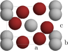 (a) \ceNi2C (058)
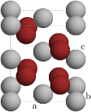 (b) \ceNi2C (060)
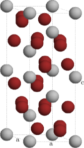
The stability of a range of nickel–carbides has been investigated by density functional calculations Gibson et al. (2010), yet, neglecting the influence of elastic deformations which we address here. The study confirmed that, without externally induced strains, \ceNi3C in space group 167 structure, figure 1LABEL:sub@fig:struct:ni3c, is the least unstable carbide and suggests that \ceNi2C is most stable in orthorhombic structures of space groups 058 (Pnnm) and 060 (Pbcn), see figures 1LABEL:sub@fig:struct:58 and LABEL:sub@fig:struct:60.
All in all, especially the phase \ceNi3C has potential technical applications in heterojunctions consisting of nickel and carbon allotropes, including CNTs, acting as electrical circuit elements, for example piezoresistive sensors Wagner et al. (2012). In these applications, the mechanical and piezoresistive properties of a potential carbide layer between nickel and the carbon structure can become relevant when the device is being strained during operation or when the layer is under constant epitaxial stress which may be caused the large surface tension of nickel Erbe et al. (2005).
The present work focuses on investigating the elastic properties of the three nickel carbides \ceNiC, \ceNi2C and \ceNi3C in their most stable crystallographic structures. Ground state properties of the carbides are compared in section III.1, the obtained elastic properties are discussed in section III.2. For the experimentally most relevant carbide, \ceNi3C, the influence of strain on the electronic transport properties is dicussed in section III.3.
II Computational Methods
II.1 Electronic Structure Calculations
NiC was calculated in rocksalt (B1) structure, for \ceNi2C the structures proposed by Gibson et al. Gibson et al. (2010) were used and for \ceNi3C the rhombohedral (bainite, space group 167) structure, which was experimentally found by Nagakura Nagakura (1957) was assumed (see figure 1LABEL:sub@fig:struct:ni3c).
All results presented here were obtained applying density functional theory (DFT), in the generalized gradient approximation (GGA) in the Perdew–Burke–Ernzerhof (PBE) parametrization Perdew et al. (1996) as exchange–correlation functional, which is known to give good results for bulk mechanical properties when comparing to experiments Kurth et al. (1999). The plane-wave implementation in the ABINIT package Gonze et al. (2009, 2002, 2005) was used, employing the projector augmented wave (PAW) method Torrent et al. (2008). The PAW atomic data sets treat and as valence for nickel PAW (2014) and carbon Meyer and Jollet (2014), respectively.
For numerical accuracy, the plane-wave cutoff was converged to (). Only, for calculations of fcc-nickel, the cutoff was set to about () in order to reach a convergence of total energy below about (\SI1e-4Ha) per atom. At this point energy differences under strain are converged to below about (\SI1e-8Ha), which is far more accurate than required for structural relaxation and the calculation of elastic properties. The stronger total energy criterion was chosen with regard to calculating formation enthalpies.
When calculating ground state properties of carbides the Brillouin zone was sampled with a Monkhorst–Pack grid of -points. Thermal smearing of Fermi-Dirac-type ABI (2015) was fixed to about (). Since the unit cells of nickel and diamond are smaller, denser grids of and -points, respectively, were required in order to get comparable sampling accuracy.
The ground state formation energies per formula unit (f.u.) for the carbides were calculated according to
| (1) |
where is the total energy of compound . Diamond was calculated as carbon reference structure instead of graphite because the employed method is not capable of correctly calculating van-der-Vaals interactions. An empiric correction of per carbon atom, also used in reference Gibson et al., 2010, was applied to obtain formation energies with respect to graphite.
II.2 Frozen Phonon Calculations
Within the linear regime, elastic properties can be described by the elastic tensor , which gives the stress response of a material proportional to a deformation :
| (2) | ||||
| Here, Voigt’s notation is used to write the stress and deformation tensors as six-vectors (; ; ; ; ; ), with entries corresponding to three axial strains () and shear strains (). In this way the elastic tensor can be written as a matrix from which all elastic properties can be derived. The bulk modulus is given by: | ||||
| (3) | ||||
where denotes an average over the diagonal axial strain entries and an average over the off–diagonal axial strain entries.
The entries of the elastic tensor were calculated using the frozen phonon (FP) method, where the stress-response was derived from ground state calculations of the deformed primitive cell. A more detailed explanation can be found in Wagner and Windl (2008). The six primitive deformations were applied separately with magnitudes ranging up to \SI1%. All elastic constants were then determined using equation (2). The diagonal entries of the tensor can also be determined from the total energies of the same calculations:
| (4) |
where and are the total energy and volume of the unstrained cell. The calculated tensors were checked for consistency by comparing the results of equations (2) and (4). The calculation parameters were converged until the difference between the diagonal tensor elements from both equations was less than \SI2GPa. This criterion called for using a -point grid for the deformed cell of \ceNiC, for the other materials it was met by using the aforementioned simulation parameters.
If the material’s unit cell exhibits internal degrees of freedom, performing a ground state calculation of the deformed cell without relaxation of the ion positions yields entries of the so-called clamped–ion elastic tensor . To obtain the more physical relaxed–ion elastic tensor , the internal atomic coordinates were relaxed using the Broyden–Fletcher–Goldfarb–Shanno algorithm as implemented in ABINIT until all forces were below \SI5e-4eV/\angstrom.
II.3 Electronic Transport
Electronic transport was calculated assuming constant relaxation time within the Boltzmann formalism where the conductivity tensor at zero temperature is given as: Ziman (1972)
| (5) |
where is the eigenenergy of the th band and the vector of the corresponding group velocity. denotes the electron charge and denote cartesian vector components.
Off-diagonal elements of are zero by symmetry. For the relaxation time no specific value is assumed, though it might be anisotropic () in the case of due to its rhombohedral structure Yavorsky et al. (2011). The integrals on the right-hand side of equation (5) reflect the anisotropy of the bandstructure of the unperturbed, but eventually strained, systems at the Fermi level. Assuming that remains constant under strain in the linear regime, since no new scattering centers are created, predictions can be made about the change of conductivity under strain.
For strained cells, the bandstructure with relaxed ion positions was used as basis for these calculations.
III Results and Discussion
III.1 Ground State Results
The lattice parameters of the investigated materials are available in literature, some even from experiments. The lattice constant calculated for fcc-nickel in the present work () agrees very well with values found in literature Hull. (1917); Gibson et al. (2010). The obtained lattice parameter for diamond () is only slightly larger than the experimental value of Yamanaka et al. (1994). Lattice parameters obtained for the carbides as well as formation enthalpies will be given for comparison, the latter with respect to fcc–\ceNi and graphite.
\ceNiC
Assuming rocksalt structure, the lattice parameter was obtained, which is in good agreement with ref. Gibson et al. (2010) (\SI4.077\angstrom) and other numerical studies cited therein. The calculated formation enthalpy of of f.u. also agrees with ref. Gibson et al. (2010) (\SI48.6kcal/mol).
| \ceNi2C (058) | \ceNi2C (060) | |
|---|---|---|
| \num4.72(\num4.72) | \num4.19(\num4.19) | |
| \num4.19(\num4.17) | \num5.51(\num5.51) | |
| \num2.93(\num2.92) | \num4.94(\num4.94) | |
| \num12.2(\num7.9) | \num12.0(\num7.9) |
\ceNi2C
The calculated values for the two investigated structures are summarized in table 1. The lattice parameters are in excellent agreement with ref. Gibson et al. (2010). Only, the formation enthalpies stated therein disagree with the present results (see table 1, values in parentheses). However, there is agreement on the prediction that both structures are essentially degenerate, with the variant of space group 060 being less than lower in total energy.
\ceNi3C
The obtained lattice parameters and are in good agreement with ref. Gibson et al. (2010) (, ) and electron diffraction measurements Nagakura (1958) (, ). A formation enthalpy of was obtained, which is identical to the value reported in ref Gibson et al. (2010) and reflects the thermal decomposition observed in Chiang et al. (2014).
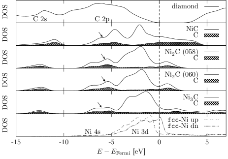
For the relaxed, strain-free geometries, all carbides of nickel investigated here are meta-stable at , non-magnetic and metallic as observed previously Gibson et al. (2010). \ceNi2C exhibits a very low density of states (DOS) around the Fermi energy. The DOS for the investigated carbides and the reference phases are plotted in figure 2.
In all carbides the \ceC 2s band is located below the conduction band. It is shifted to lower energies (shifted left in figure 2) for \ceNi2C and \ceNi3C in comparison to the carbide with higher carbon content, \ceNiC, indicating a deeper potential well for electrons is provided by the carbon atoms. They are also more strongly negatively charged than in \ceNiC. The \ceNi 3d states are located below the Fermi energy above about for \ceNi2C and \ceNi3C, for \ceNiC they are spread over a broader energy range, starting at around . The \ceNi 3d orbitals do contribute to the DOS at the Fermi level, but much less than in fcc-nickel, where the 3d-DOS of the minority spin peaks at the Fermi level. \ceNi 4s and \ceC 2p states also contribute to the DOS at the Fermi level. The part of the conduction band below about is predominately composed of \ceC 2p states hybridizing with \ceNi states, see arrows in figure 2.
III.2 Elastic Constants
As a reference, the elastic tensors of fcc-\ceNi and diamond were calculated and the non-zero, not symmetrically equivalent elements are provided in table 2. The calculated bulk modulus for diamond is identical to earlier theoretical works Cohen (1985) and also the tensor components agree with earlier literature data Telling et al. (2000). The bulk modulus for \ceNi is within about \SI10GPa of experimental results Rekhi et al. (2001). This deviation is predominantly attributed to the approximations involved in DFT. The following predictions for the elastic properties of nickel carbides can be expected to have about the same accuracy.
All carbides exhibit a larger bulk modulus than Nickel and a much lower one than diamond, as apparent from the last column of table 2. Being the carbide with the highest carbon content, \ceNiC shows the largest bulk modulus of the carbides. Evidently, the bulk modulus increases with increasing carbon content, that is, the substances become harder. Table 2 lists all calculated non-zero and not symmetrically equivalent elastic constants. The carbides \ceNi2C and \ceNi3C exhibit less symmetric unit cells, resulting in more independent entries in the elastic tensor.
\ceNi2C
Both investigated hypothetical forms of \ceNi2C are predicted to be equally hard and even show quite similar anisotropies, probably due to the fact that both are orthorhombic. The elastic properties of the sample should not depend on the relative prevalence of these two phases. Still, judging by the elastic tensors, deforming one cell into the equilibrium shape of the other and allowing the atoms to rearrange into the other structure by relaxation requires overcoming a large potential barrier. Thus, even under stress, both structures can be expected to coexist in one sample.
\ceNi3C
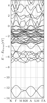
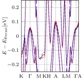
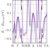
Judging by the obtained bulk moduli, a macroscopically isotropic polycrystalline sample of \ceNi3C is predicted to be about as hard as the less stable \ceNi2C. Even for the most extreme simulated deformations of \SI1% stresses were found to be still in the linear regime. Using the calculated value for , a compression in –direction of this magnitude corresponds to applying a pressure of about , which by far exceeds pressures achievable in most experiments.
Investigating DOS and band structure of deformed cells, no qualitative difference with respect to that obtained for the equilibrium geometry was found. For purely axial strains and compressions (i.e. , and , see figure 3LABEL:sub@fig:bands:zz) bands move slightly closer to the Fermi-level under strain and further away under compression. This can be attributed to changing overlaps between atomic orbitals. This difference is marginal close to and at the Fermi level, the region most relevant to transport properties. For pure shear deformations no significant changes are observed, see figure 3LABEL:sub@fig:bands:yz. Band structures shown in figure 3 for deformed cells use relaxed ion positions. Clamped cells show qualitatively identical changes, only the shift of bands for strains and compressions is larger.
| diamond | \num1049 | \num129 | \num564 | \num435 | |||||||
| \ceNiC | \num296 | \num231 | \num50 | \num256 | |||||||
| \ceNi2C (058), clamped | 316 | 262 | 378 | 218 | 175 | 193 | 116 | 91 | 145 | 236 | |
| \ceNi2C (058), relaxed | 307 | 234 | 344 | 203 | 160 | 163 | 88 | 87 | 145 | 215 | |
| \ceNi2C (060), clamped | 279 | 343 | 359 | 213 | 203 | 171 | 90 | 125 | 135 | 239 | |
| \ceNi2C (060), relaxed | 251 | 333 | 335 | 205 | 186 | 163 | 78 | 91 | 113 | 225 | |
| \ceNi3C clamped | 321 | 309 | 176 | 184 | 116 | 72 | -11 | 227 | |||
| \ceNi3C relaxed | 272 | 276 | 157 | 150 | 91 | 57 | -22 | 219 | |||
| fcc-\ceNi | \num266 | \num156 | \num129 | \num192 |
III.3 Electronic Transport under Strain
A closer analysis of the \ceNi3C band structure yields a density of states of \SI2.83eV^-1 per f.u. and anisotropic averaged Fermi velocities of and . This results in an in-plane/out-of-plane conductivity anisotropy of about .
The respective effect of axial strains in and direction ( and ) on electronic transport was investigated. For strains up to the DOS remains unaffected within the precision of the calculation. Table 3 summarizes relative changes under strain in both conductance and Fermi velocities. The strongest changes in conductance can be observed for strains along , where the parallel conductance in direction changes by , the anisotropy increases slightly. For small strains along the in-plane isotropy () is unaffected, while the in-plane/out-of-plane anisotropy changes slightly.
Computational and analytical investigations of the piezoresistivity of semi-conducting CNTs suggest an increase in resistance of well above \SI50% under longitudinal strains of about \SI.3% Dmitrović et al. (2015); Wagner et al. (2016). To exert the required stress on a \ceNi3C-contacted CNT, the contact material would be strained by about \SI1%, given the ratio of the established Young’s modulus of CNTs of about \SI1000GPa Wu et al. (2008) and the elastic coefficients we obtained for axial strains in \ceNi3C. This would cause a change in conductivity of 3 to \SI10% in the contact material, which is significantly smaller than the effect observed in the CNT. Thus, the piezoresistive properties of a device with \ceNi-contacted CNTs as functional structure are dominated by the electronic response of the CNTs to mechanical deformations.
For isotropic compression of a polycrystalline sample, linear combination of the axial effects suggests a reduction of conductivity. This is mostly a result of the relatively large decrease in conductivity by axial compression in direction.
The piezoresistive effect observed by Uhlig et al. in \ceNi3C–containing nickel–carbon thin films Uhlig et al. (2013a, b) under hydrostatic pressure is opposite to this prediction for bulk \ceNi3C based on our calculations. Thus our study excludes the possibility, that these observations are dominated by bulk effects in \ceNi3C grains. One may speculate that they emerge from effects in nickel grains, since nickel itself is known to show piezoresistive effects Kuczynski (1954); Klokholm (1973). Effects at interfaces in the nickel–carbon mixture may also play a role.
| strain | ||||
|---|---|---|---|---|
IV Conclusions
The complete sets of elastic constants of nickel carbides have been calculated in a way that they can be expected to be within \SI10GPa of experimental values. The electronic structure and electronic transport properties of bulk \ceNi3C under stress have been investigated. Assuming a constant relaxation time , changes in conductivity not exceeding about in-plane and about out-of-plane for stresses below are predicted. As a contact material in sensing applications these changes are of minor significance. These results also show, that \ceNi3C does not contribute significantly to the piezoresistive effects observed in nickel–carbon thin films by Uhlig and coworkers Uhlig et al. (2013a).
For the formation enthalpy of both \ceNi2C variants, the absolute values obtained here differ quantitatively from those by Gibson et al. Gibson et al. (2010), but qualitatively both studies agree on the relative ordering with respect to the other carbide phases. On the enthalpy difference between the ground state \ceNi2C variants the agreement is excellent. The studies also agree on the formation enthalpies of the other carbides.
Acknowledgments
We thank R. Wenisch for fruitful discussions. This work has been partially financed by the Initiative and Networking Fund of the German Helmholtz Association via the Helmholtz International Research School NanoNet (VH-KO-606) and the W2/W3 Programm für exzellente Wissenschaftlerinnen (W2/W3-026). We gratefully acknowledge partial funding by the DFG via Research Unit FOR1713 (SMINT) and the Center for Advancing Electronics Dresden (cfaed). We thank the HZDR computing center for provided computational resources.
References
- Uhlig et al. (2013a) Steffen Uhlig, Hanna Schmid-Engel, Tobias Speicher, and Günter Schultes. Pressure sensitivity of piezoresistive nickel-carbon Ni:a-C:H thin films. Sens. Actuators A, 193(0):129–135, 2013a. ISSN 0924-4247. doi: 10.1016/j.sna.2012.12.027. URL http://www.sciencedirect.com/science/article/pii/S0924424712007649.
- Schaefer et al. (2011) Zachary L Schaefer, Kaitlyn M Weeber, Rajiv Misra, Peter Schiffer, and Raymond E Schaak. Bridging hcp-Ni and Ni3C via a Ni3C1-x Solid Solution: Tunable Composition and Magnetism in Colloidal Nickel Carbide Nanoparticles. Chem. Mater., 23(9):2475–2480, 2011.
- Uhlig et al. (2013b) Steffen Uhlig, Rudolf Struis, Hanna Schmid-Engel, Jochen Bock, Anne-Catherine Probst, Olivia Freitag-Weber, Ivo Zizak, Roman Chernikov, and Günter Schultes. Piezoresistive Ni:a-C:H thin films containing hcp-Ni or Ni3C investigated by XRD, EXAFS, and wavelet analysis. Diam. Relat. Mater., 34(0):25–35, 2013b. ISSN 0925-9635. doi: 10.1016/j.diamond.2013.01.013. URL http://www.sciencedirect.com/science/article/pii/S092596351300023X.
- He (2010) Lin He. Hexagonal close-packed nickel or Ni3C? Journal of Magnetism and Magnetic Materials, 322(14):1991–1993, 2010. ISSN 0304-8853. doi: 10.1016/j.jmmm.2010.01.020. URL http://www.sciencedirect.com/science/article/pii/S0304885310000387.
- Furlan et al. (2014) Andrej Furlan, Jun Lu, Lars Hultman, Ulf Jansson, and Martin Magnuson. Crystallization characteristics and chemical bonding properties of nickel carbide thin film nanocomposites. J. Phys. Condens. Matter, 26(41):415501, 2014. URL http://stacks.iop.org/0953-8984/26/i=41/a=415501.
- Bayer et al. (2016) Bernhard C. Bayer, David A. Bosworth, F. Benjamin Michaelis, Raoul Blume, Gerlinde Habler, Rainer Abart, Robert S. Weatherup, Piran R. Kidambi, Jeremy J. Baumberg, Axel Knop-Gericke, Robert Schloegl, Carsten Baehtz, Zoe H. Barber, Jannik C. Meyer, and Stephan Hofmann. In Situ Observations of Phase Transitions in Metastable Nickel (Carbide)/Carbon Nanocomposites. J. Phys. Chem. C, 120(39):22571–22584, 2016. doi: 10.1021/acs.jpcc.6b01555. URL http://dx.doi.org/10.1021/acs.jpcc.6b01555.
- Sato et al. (2003) Shintaro Sato, Akio Kawabata, Mizuhisa Nihei, and Yuji Awano. Growth of diameter-controlled carbon nanotubes using monodisperse nickel nanoparticles obtained with a differential mobility analyzer . Chem. Phys. Lett., 382(3-4):361–366, 2003. ISSN 0009-2614. doi: 10.1016/j.cplett.2003.10.076. URL http://www.sciencedirect.com/science/article/pii/S0009261403018608.
- Börjesson and Bolton (2010) Anders Börjesson and Kim Bolton. First Principles Studies of the Effect of Nickel Carbide Catalyst Composition on Carbon Nanotube Growth. J. Phys. Chem. C, 114(42):18045–18050, 2010. doi: 10.1021/jp1045707. URL http://pubs.acs.org/doi/abs/10.1021/jp1045707.
- Krause et al. (2012) Matthias Krause, Miro Haluška, Gintautas Abrasonis, and Sibylle Gemming. SWCNT growth from C:Ni nanocomposites. Phys. Status Solidi B, 249(12):2357–2360, 2012. ISSN 1521-3951. doi: 10.1002/pssb.201200107. URL http://dx.doi.org/10.1002/pssb.201200107.
- Lin et al. (2006) Ming Lin, Joyce Pei Ying Tan, Chris Boothroyd, Kian Ping Loh, Eng Soon Tok, and Yong-Lim Foo. Direct Observation of Single-Walled Carbon Nanotube Growth at the Atomistic Scale. Nano Lett., 6(3):449–452, 2006. doi: 10.1021/nl052356k. URL http://dx.doi.org/10.1021/nl052356k.
- Ducati et al. (2004) C. Ducati, I. Alexandrou, M. Chhowalla, J. Robertson, and G. A. J. Amaratunga. The role of the catalytic particle in the growth of carbon nanotubes by plasma enhanced chemical vapor deposition. J. Appl. Phys., 95(11):6387–6391, 2004. doi: 10.1063/1.1728293. URL http://scitation.aip.org/content/aip/journal/jap/95/11/10.1063/1.1728293.
- Zhou et al. (2008) Wei Zhou, Kun Zheng, Lin He, Rongming Wang, Lin Guo, Chinping Chen, Xiaodong Han, and Ze Zhang. Ni/Ni3C Core–Shell Nanochains and Its Magnetic Properties: One-Step Synthesis at Low Temperature. Nano Lett., 8(4):1147–1152, 2008. doi: 10.1021/nl073291j. URL http://dx.doi.org/10.1021/nl073291j. PMID: 18358008.
- Cao et al. (2015) Qing Cao, Shu-Jen Han, Jerry Tersoff, Aaron D. Franklin, Yu Zhu, Zhen Zhang, George S. Tulevski, Jianshi Tang, and Wilfried Haensch. End-bonded contacts for carbon nanotube transistors with low, size-independent resistance. Science, 350(6256):68–72, 2015. ISSN 0036-8075. doi: 10.1126/science.aac8006. URL http://science.sciencemag.org/content/350/6256/68.
- McDonough et al. (2009) James R. McDonough, Jang Wook Choi, Yuan Yang, Fabio La Mantia, Yuegang Zhang, and Yi Cui. Carbon nanofiber supercapacitors with large areal capacitances. Appl. Phys. Lett., 95(24):243109, 2009. doi: 10.1063/1.3273864. URL http://scitation.aip.org/content/aip/journal/apl/95/24/10.1063/1.3273864.
- Zheng et al. (2010) Maxwell Zheng, Kuniharu Takei, Benjamin Hsia, Hui Fang, Xiaobo Zhang, Nicola Ferralis, Hyunhyub Ko, Yu-Lun Chueh, Yuegang Zhang, Roya Maboudian, and Ali Javey. Metal-catalyzed crystallization of amorphous carbon to graphene. Appl. Phys. Lett., 96(6):063110, 2010. doi: 10.1063/1.3318263. URL http://scitation.aip.org/content/aip/journal/apl/96/6/10.1063/1.3318263.
- Wenisch et al. (2016) R. Wenisch, R. Hübner, F. Munnik, S. Melkhanova, S. Gemming, G. Abrasonis, and M. Krause. Nickel-enhanced graphitic ordering of carbon ad-atoms during physical vapor deposition. Carbon, 100:656–663, 2016. ISSN 0008-6223. doi: 10.1016/j.carbon.2015.12.085. URL http://www.sciencedirect.com/science/article/pii/S0008622315305510.
- Grandthyll et al. (2012) Samuel Grandthyll, Stefan Gsell, Michael Weinl, Matthias Schreck, Stefan Hüfner, and Frank Müller. Epitaxial growth of graphene on transition metal surfaces: chemical vapor deposition versus liquid phase deposition. J. Phys. Condens. Matter, 24(31):314204, 2012. URL http://stacks.iop.org/0953-8984/24/i=31/a=314204.
- Weatherup et al. (2011) Robert S. Weatherup, Bernhard C. Bayer, Raoul Blume, Caterina Ducati, Carsten Baehtz, Robert Schlögl, and Stephan Hofmann. In Situ Characterization of Alloy Catalysts for Low-Temperature Graphene Growth. Nano Lett., 11(10):4154–4160, 2011. doi: 10.1021/nl202036y. URL http://dx.doi.org/10.1021/nl202036y.
- Lahiri et al. (2011) Jayeeta Lahiri, Travis S Miller, Andrew J Ross, Lyudmyla Adamska, Ivan I Oleynik, and Matthias Batzill. Graphene growth and stability at nickel surfaces. New J. Phys., 13(2):025001, 2011. URL http://stacks.iop.org/1367-2630/13/i=2/a=025001.
- Jacobson et al. (2012) Peter Jacobson, Bernhard Stöger, Andreas Garhofer, Gareth S. Parkinson, Michael Schmid, Roman Caudillo, Florian Mittendorfer, Josef Redinger, and Ulrike Diebold. Nickel Carbide as a Source of Grain Rotation in Epitaxial Graphene. ACS Nano, 6(4):3564–3572, 2012. doi: 10.1021/nn300625y. URL http://dx.doi.org/10.1021/nn300625y.
- Gibson et al. (2010) Josh S Gibson, Jamal Uddin, Thomas R Cundari, Nelli K Bodiford, and Angela K Wilson. First-principle study of structure and stability of nickel carbides. J. Phys. Condens. Matter, 22(44):445503, 2010. URL http://stacks.iop.org/0953-8984/22/i=44/a=445503.
- Wagner et al. (2012) Christian Wagner, Jörg Schuster, and Thomas Gessner. DFT investigations of the piezoresistive effect of carbon nanotubes for sensor application. Phys. Status Solidi B, 249(12):2450–2453, 2012. ISSN 1521-3951. doi: 10.1002/pssb.201200113. URL http://dx.doi.org/10.1002/pssb.201200113.
- Erbe et al. (2005) A. Erbe, W. Jiang, Z. Bao, D. Abusch-Magder, D. M. Tennant, E. Garfunkel, and N. Zhitenev. Nanoscale patterning in application to materials and device structures. J. Vac. Sci. Technol. B, 23(6):3132–3137, 2005. doi: 10.1116/1.2130353. URL http://scitation.aip.org/content/avs/journal/jvstb/23/6/10.1116/1.2130353.
- Nagakura (1957) Sigemaro Nagakura. Study of Metallic Carbides by Electron Diffraction Part I. Formation and Decomposition of Nickel Carbide. J. Phys. Soc. Jpn., 12(5):482–494, 1957. doi: 10.1143/JPSJ.12.482. URL http://jpsj.ipap.jp/link?JPSJ/12/482.
- Perdew et al. (1996) John P. Perdew, Kieron Burke, and Matthias Ernzerhof. Generalized Gradient Approximation Made Simple. Phys. Rev. Lett., 77(18):3865–3868, 1996. doi: 10.1103/PhysRevLett.77.3865. URL http://link.aps.org/doi/10.1103/PhysRevLett.77.3865;http://www.bibsonomy.org/bibtex/2507b0512ae6a0b380c7ffe99c4ac0648/chengguang.
- Kurth et al. (1999) Stefan Kurth, John P. Perdew, and Peter Blaha. Molecular and solid-state tests of density functional approximations: LSD, GGAs, and meta-GGAs. Int. J. Quant. Chem., 75(4-5):889–909, 1999. ISSN 1097-461X. doi: 10.1002/(SICI)1097-461X(1999)75:4/5¡889::AID-QUA54¿3.0.CO;2-8. URL http://dx.doi.org/10.1002/(SICI)1097-461X(1999)75:4/5<889::AID-QUA54>3.0.CO.
- Gonze et al. (2009) Xavier Gonze, B. Amadon, P.-M. Anglade, Jean-Michel Beuken, F. Bottin, P. Boulanger, F. Bruneval, D. Caliste, R Caracas, M. Côté, Thierry Deutsch, Luigi Genovese, Ph. Ghosez, M. Giantomassi, Stefan Goedecker, DR Hamann, P. Hermet, F. Jollet, G. Jomard, and S. Leroux. ABINIT: First-principles approach to material and nanosystem properties. Comput. Phys. Commun., 180(12):2582–2615, 2009. URL http://dblp.uni-trier.de/db/journals/cphysics/cphysics180.html#GonzeAABBBBCCCDGGGGHHJJL09;http://dx.doi.org/10.1016/j.cpc.2009.07.007;http://www.bibsonomy.org/bibtex/2ba2264f9584526062c5945ddef54d46f/dblp.
- Gonze et al. (2002) Xavier Gonze, J. Beuken, R Caracas, F. Detraux, M. Fuchs, G. Rignanese, L. Sindic, M. Verstraete, G. Zerah, F. Jollet, M. Torrent, A. Roy, M. Mikami, P Ghosez, J. Raty, and DC Allan. First-principles computation of material properties: the ABINIT software project. Comput. Mater. Sci., 25(3):478–492, 2002. doi: 10.1016/S0927-0256(02)00325-7. URL http://www.ingentaconnect.com/content/els/09270256/2002/00000025/00000003/art00325.
- Gonze et al. (2005) Xavier Gonze, GM Rignanese, M. Verstraete, JM Beuken, Y Pouillon, R Caracas, F. Jollet, M. Torrent, G Zerah, M. Mikami, P Ghosez, M Veithen, JY Raty, V Olevano, F Bruneval, L Reining, R Godby, G Onida, DR Hamann, and DC Allan. A brief introduction to the ABINIT software package. Z. Kristallogr., 220(5-6):558–562, 2005. ISSN 0044-2968. doi: 10.1524/zkri.220.5.558.65066.
- Torrent et al. (2008) Marc Torrent, François Jollet, François Bottin, Gilles Zérah, and Xavier Gonze. Implementation of the projector augmented-wave method in the ABINIT code: Application to the study of iron under pressure. Comput. Mater. Sci., 42(2):337–351, 2008. ISSN 0927-0256. URL http://dx.doi.org/10.1016/j.commatsci.2007.07.020.
- PAW (2014) ABINIT PAW Atomic Data Ni, September 2014. URL http://www.abinit.org/downloads/PAW2/TABLES/MAIN/028-ni/Ni-GGA-atompaw.
- Meyer and Jollet (2014) Bernd Meyer and Francois Jollet. ABINIT PAW Atomic Data C, September 2014. URL http://www.abinit.org/downloads/PAW2/TABLES/MAIN/006-c/C-GGA-hard-uspp.
- ABI (2015) ABINIT Input Variable occopt, October 2015. URL http://www.abinit.org/doc/helpfiles/for-v7.10/input_variables/varbas.html#occopt.
- Wagner and Windl (2008) Martin F.-X. Wagner and Wolfgang Windl. Lattice stability, elastic constants and macroscopic moduli of NiTi martensites from first principles. Acta Mater., 56(20):6232–6245, 2008. ISSN 1359-6454. doi: 10.1016/j.actamat.2008.08.043. URL http://www.sciencedirect.com/science/article/pii/S1359645408006083.
- Ziman (1972) J. M. Ziman. Principles of the Theory of Solids. Cambridge University Press, second edition, 1972. ISBN 9781139644075. URL http://dx.doi.org/10.1017/CBO9781139644075. Cambridge Books Online.
- Yavorsky et al. (2011) B. Yu. Yavorsky, N. F. Hinsche, I. Mertig, and P. Zahn. Electronic structure and transport anisotropy of Bi2Te3 and Sb2Te3. Phys. Rev. B, 84:165208, Oct 2011. doi: 10.1103/PhysRevB.84.165208. URL http://link.aps.org/doi/10.1103/PhysRevB.84.165208.
- Hull. (1917) A. Hull. A New Method of X-Ray Crystal Analysis. Phys. Rev., 10:661–696, Dec 1917. doi: 10.1103/PhysRev.10.661. URL http://link.aps.org/doi/10.1103/PhysRev.10.661.
- Yamanaka et al. (1994) T. Yamanaka, S. Morimoto, and H. Kanda. Influence of the isotope ratio on the lattice constant of diamond. Phys. Rev. B, 49:9341–9343, Apr 1994. doi: 10.1103/PhysRevB.49.9341. URL http://link.aps.org/doi/10.1103/PhysRevB.49.9341.
- Nagakura (1958) Sigemaro Nagakura. Study of Metallic Carbides by Electron Diffraction Part II. Crystal Structure Analysis of Nickel Carbide. J. Phys. Soc. Jpn., 13(9):1005–1014, 1958. doi: 10.1143/JPSJ.13.1005. URL http://jpsj.ipap.jp/link?JPSJ/13/1005.
- Chiang et al. (2014) Ray-Tung Chiang, Ray-Kuang Chiang, and Fuh-Sheng Shieu. Emergence of interstitial-atom-free HCP nickel phase during the thermal decomposition of Ni3C nanoparticles. RSC Adv., 4:19488–19494, 2014. doi: 10.1039/C4RA01874E. URL http://dx.doi.org/10.1039/C4RA01874E.
- Cohen (1985) Marvin Cohen. Calculation of bulk moduli of diamond and zinc-blende solids. Phys. Rev. B, 32:7988–7991, Dec 1985. doi: 10.1103/PhysRevB.32.7988. URL http://link.aps.org/doi/10.1103/PhysRevB.32.7988.
- Telling et al. (2000) R. H. Telling, C. J. Pickard, M. C. Payne, and J. E. Field. Theoretical Strength and Cleavage of Diamond. Phys. Rev. Lett., 84:5160–5163, May 2000. doi: 10.1103/PhysRevLett.84.5160. URL http://link.aps.org/doi/10.1103/PhysRevLett.84.5160.
- Rekhi et al. (2001) S. Rekhi, S.K. Saxena, R. Ahuja, B. Johansson, and J. Hu. Experimental and theoretical investigations on the compressibility of nanocrystalline nickel. J. Mater. Sci., 36(19):4719–4721, 2001. ISSN 0022-2461. doi: 10.1023/A:1017974904559. URL http://dx.doi.org/10.1023/A%3A1017974904559.
- Dmitrović et al. (2015) Saša Dmitrović, Ivanka Milošević, Milan Damnjanović, and Tatjana Vuković. Electronic Properties of Strained Carbon Nanotubes: Impact of Induced Deformations. J. Phys. Chem. C, 119(24):13922–13928, 2015. doi: 10.1021/acs.jpcc.5b02455. URL http://dx.doi.org/10.1021/acs.jpcc.5b02455.
- Wagner et al. (2016) Christian Wagner, Jörg Schuster, and Thomas Gessner. Empirical transport model of strained CNT transistors used for sensor applications. J. Comput. Electron., 15(3):881–890, 2016. ISSN 1572-8137. doi: 10.1007/s10825-016-0823-4. URL http://dx.doi.org/10.1007/s10825-016-0823-4.
- Wu et al. (2008) Yang Wu, Mingyuan Huang, Feng Wang, X. M. Henry Huang, Sami Rosenblatt, Limin Huang, Hugen Yan, Stephen P. O’Brien, James Hone, and Tony F. Heinz. Determination of the Young’s Modulus of Structurally Defined Carbon Nanotubes. Nano Lett., 8(12):4158–4161, 2008. doi: 10.1021/nl801563q. URL http://dx.doi.org/10.1021/nl801563q.
- Kuczynski (1954) G. C. Kuczynski. Effect of Elastic Strain on the Electrical Resistance of Metals. Phys. Rev., 94:61–64, Apr 1954. doi: 10.1103/PhysRev.94.61. URL http://link.aps.org/doi/10.1103/PhysRev.94.61.
- Klokholm (1973) E. Klokholm. Piezoresistance in Evaporated Nickel Films. J. Vac. Sci. Technol., 10(1):235–237, 1973. doi: 10.1116/1.1317950. URL http://scitation.aip.org/content/avs/journal/jvst/10/1/10.1116/1.1317950.