Large-Scale Production of Monitored Drift Tube Chambers for the ATLAS Muon Spectrometer
Abstract
Precision drift tube chambers with a sense wire positioning accuracy of better than m are under construction for the ATLAS muon spectrometer. of the 88 large chambers for the outermost layer of the central part of the spectrometer have been assembled. Measurements during chamber construction of the positions of the sense wires and of the sensors for the optical alignment monitoring system demonstrate that the requirements for the mechanical precision of the chambers are fulfilled.
1 Introduction
The muon spectrometer [1] is one of the main characteristics of the ATLAS experiment at the Large Hadron Collider (LHC). It has been designed to measure muon momenta in the range from 10 to 1000 GeV with an accuracy of 3 to over a pseudo-rapidity range of . The muon trajectories in the 0.5 T toroidal magnetic field of superconducting air-core magnets are measured by three stations of precision drift chambers, the Monitored Drift Tube (MDT) chambers. The MDT chambers consist of a pair of triple layers of drift tubes (quadruple layers in the innermost station) mounted on a light aluminum space frame. The aluminum drift tubes of 30 mm diameter contain m diameter gold-plated W-Re sense wires and are operated with Ar:CO2 (93:7) gas mixture at a pressure of 3 bar and a gas gain of .

The muon chambers have to provide a position resolution of m. With a single-tube resolution of m [2], this is achieved by requiring a positioning accuracy of the sense wires in a chamber of better than m (rms). The relative positions of the MDT chambers in the ATLAS detector are continuously measured by an optical alignment monitoring system [1] which is designed to provide misalignment corrections to the muon sagittae with an accuracy of m (rms). The precision of the misalignment corrections is directly proportional to the positioning accuracy of the optical sensors mounted on the chambers which is required to be m with respect to the sense wires.
1200 MDT chambers covering an active area of 5000 m2 are under construction for the ATLAS muon spectrometer. The MPI Munich is responsible for the production of 88 chambers for the outermost layer of the central part of the spectrometer covering of the active area. Each chamber contains 432 drift tubes of 3.8 m length. of the chambers have already been assembled.
2 Chamber Assembly and Monitoring
The MDT chamber assembly procedure has been described in [3],[4]. The required mechanical precision of the chambers is achieved in two steps. During the assembly of the drift tubes, the sense wires are centered at the tube ends with an accuracy of m (rms) as verified by X-ray measurements of every drift tube [3]. In the second step, the 72 drift tubes of a tube layer are positioned on the chamber assembly table with an accuracy of m (rms) [4] at the tube ends verified by measurements with mechanical feeler gauges [3].
The tube layers positioned on the assembly table are consecutively glued to the space frame which, for this purpose, is positioned on the table with an accuracy of m with respect to the tubes. The effects of glue shrinkage on the geometry are anticipated. The gravitational deformations of the space frame supported on the table are measured by optical sensors (RASNIK imaging systems developed by NIKHEF consisting of an illuminated grid pattern, a focusing lens and a CCD camera) and are compensated during glueing of the chambers by computer-controlled pneumatic actuators.
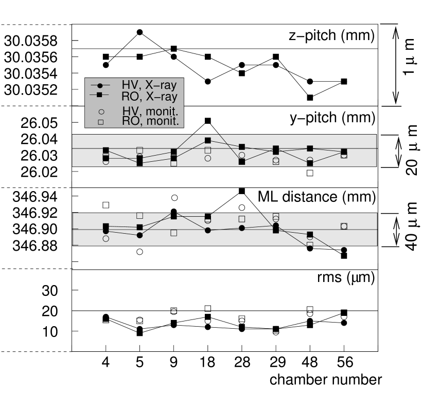
The wire positioning accuracy of the chambers is determined by the precision of the assembly tools. For about of the chambers, the assembly precision is verified by wire position measurements of m (rms) precision with an X-ray scanning device at CERN [5]. The measured geometrical parameters of the wire grid, the wire pitch in the directions parallel () and vertical () to the assembly table and the distance between the triple layers (ML), are reproducible and in good agreement with the nominal values (see Fig. 1). The wire positioning accuracy fulfills the requirement; the average accuracy of the chambers X-rayed is m (see Fig. 1).
In order to monitor the accuracy of the chambers during the construction, the geometrical chamber parameters are measured at the four corners of the space frame with dedicated RASNIK sensors which provide a measurement accuracy of m. The optical measurements of the pitch and of the triple layer (ML) distance are in good agreement with the nominal values and with the X-ray measurements as shown in Fig. 1 and are found to be reproducible during chamber construction within m and m (rms), respectively.
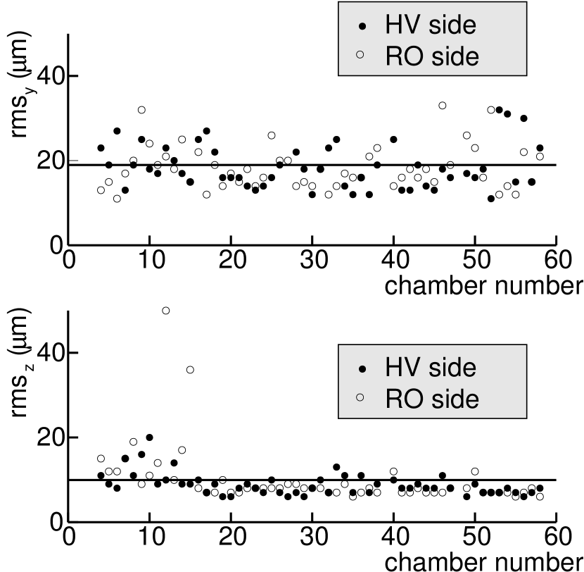
By combining the optical measurements of the layer and triple layer positions with the additional information from the tube position measurements on the assembly table and the wire positions in the individual drift tubes, the wire coordinates within a chamber can be determined. The rms values of the residual distributions of the reconstructed wire positions with respect to the nominal values and with respect to the X-ray measurements are shown as a function of the chamber number in Figs. 2 and 1, respectively. The and coordinates of the wires are reconstructed with average accuracies of m and m, respectively.
3 Alignment Sensor Positioning
The sensors for the optical alignment monitoring system are mounted on aluminum platforms glued to the triple layers with precise jigs. The positions of the platforms with respect to the sense wires are measured with mechanical feeler gauges on the assembly table with accuracies of m and m in and direction, respectively. The measured positions are found to be within the required tolerances and agree with X-ray measurements of the platform positions at CERN (see Fig. 3). The angular orientations of the platforms are measured with the same method with accuracies of rad, sufficient to determine them within the required tolerances.
4 Conclusions
The construction of precision drift tube chambers for the ATLAS muon spectrometer is well advanced. The chambers fulfill the requirements for the positioning of the sense wires and of the sensors for the optical alignment monitoring system as verified by measurements during chamber construction.
Acknowledgements
We thank the X-ray tomograph group at CERN for the careful measurement of our chambers and for providing their results to us.
References
- [1] The ATLAS Muon Collaboration, ATLAS Muon Spectrometer–Technical Design Report, CERN/LHCC/97-22, Geneva, May 1997.
- [2] M. Deile et al., MPI-PhE/2003-03, these proceedings.
- [3] F. Bauer et al., MPI Report, MPI-PhE/2002-04, October 2002.
- [4] F. Bauer et al., Nucl. Instr. and Meth. A 461 (2001) 17; IEEE Trans. Nucl. Sci., vol. 8, no. 3 (2001) 302.
- [5] J. Berbiers et al., Nucl. Instr. and Meth. A 419 (1998) 342.