Development of Fast High-Resolution Muon Drift-Tube Detectors for High Counting Rates
Abstract
Pressurized drift-tube chambers are efficient detectors for high-precision tracking over large areas. The Monitored Drift-Tube (MDT) chambers of the muon spectrometer of the ATLAS detector at the Large Hadron Collider (LHC) reach a spatial resolution of 35 m and almost tracking efficiency with 6 layers of 30 mm diameter drift tubes operated with Ar:CO2 (93:7) gas mixture at 3 bar and a gas gain of 20000. The ATLAS MDT chambers are designed to cope with background counting rates due to neutrons and rays of up to about 300 kHz per tube which will be exceeded for LHC luminosities larger than the design value of cm-1 s-1. Decreasing the drift-tube diameter to 15 mm while keeping the other parameters, including the gas gain, unchanged reduces the maximum drift time from about 700 ns to 200 ns and the drift-tube occupancy by a factor of 7. New drift-tube chambers for the endcap regions of the ATLAS muon spectrometer have been designed. A prototype chamber consisting of 12 times 8 layers of 15 mm diameter drift tubes of 1 m length has been constructed with a sense wire positioning accuracy of 20 m. The 15 mm diameter drift-tubes have been tested with cosmic rays in the Gamma Irradiation Facility at CERN at counting rates of up to 1.85 MHz.
keywords:
Muon chambers , drift tubes , high rates , LHC1 Introduction
The muon detectors of the experiments at the Large Hadron Collider (LHC) will encounter unprecedentedly high background counting rates due to neutrons and rays in the energy range up to about 10 MeV which originate mainly from secondary interactions of the hadronic collision products with accelerator elements, shielding material and the detector components. The LHC schedule foresees a continuous increase of the luminosity eventually exceeding the original design value of cm-2 s-1. Assuming that the background rates approximately scale with the luminosity, the rate capability of the muon detectors will be exceeded. The Monitored Drift-Tube (MDT) chambers in the muon spectrometer of the ATLAS detector at the LHC [1, 2], for example, are designed to cope with counting rates of up to about 300 kHz in the endcap regions of the spectrometer corresponding to an occupancy of .
The MDT chambers consist of two triple or quadruple layers (multilayers) of aluminum drift tubes of 30 mm outer diameter and 0.4 mm wall thickness filled with Ar:CO2 (93:7) gas mixture at a pressure of 3 bar. A voltage of 3080 V is applied between the tube wall and the m diameter anode wire corresponding to a gas gain of at low counting rates and resulting in a maximum drift time of about 700 ns. At low counting rates, the average spatial resolution of individual drift tubes is m applying time-slewing corrections based on pulse height measurement [3]. With a sense-wire positioning accuracy of better than m, this corresponds to a chamber spatial resolution of 35 m.
We investigate the possibility of using pressurized drift-tube detectors with smaller tube diameter and therefore shorter maximum drift-time in the highest background regions of the muon detectors of the LHC experiments. Building on the experience with the ATLAS MDT chambers, new muon drift-tube detectors with 15 mm diameter tubes have been developed which can cope with 10 times higher background fluxes.

2 Drift-tube performance at high rates
At high counting rates, the drift tubes of the ATLAS MDT chambers are known to suffer from a degradation of the spatial resolution due to space-charge effects [4, 5] and of the muon detection efficiency due to the increased drift-tube occupancy [3]. Both effects can be supressed by reducing the tube diameter while leaving the other operating parameters of the drift tubes, in particular gas mixture, pressure and gas gain, unchanged.
Decreasing the drift-tube diameter from 30 mm to 15 mm and the operating voltage from 3080 to 2730 V leads to a reduction of the maximum drift time by a factor of 3.5 from about 700 ns to 200 ns [6]. In addition, the background counting rate, dominated by the conversion of the neutron and gamma radiation in the tube walls, decreases proportional to the tube diameter, i.e. by a factor of two per unit tube length. Both effects together lead to a reduction of the occupancy by about a factor of 7. At the same time, at least twice the number of drift-tube layers can be accommodated in the same detector volume allowing for additional improvement of the muon detection efficiency and spatial resolution.
At high counting rates, the space-charge generated by the ion clouds drifting towards the tube wall lowers the effective potential near the anode wire leading to a reduction of the gas gain. The resulting loss in signal height and, therefore, spatial resolution grows with the inner tube radius proportional to [7] where m is the wire radius. Therefore, the signal height reduction due to space charge is 10 times smaller in 15 mm compared to 30 mm diameter tubes. Fluctuations of the space charge and, consequently, of the electric field in the tube lead to variations of the drift velocity in non-linear drift gases like Ar:CO2 (93:7) causing a deterioration of the spatial resolution which increases rapidly with the drift distance above a value of about 7.5 mm [4, 5]. In addition, the space-to-drift time relationship for the Ar:CO2 (93:7) drift gas is more linear at drift distances below 7.5 mm reducing the sensitivity of the position measurement to environmental parameters such as gas composition and density, magnetic field and, in particular, irradiation rate.
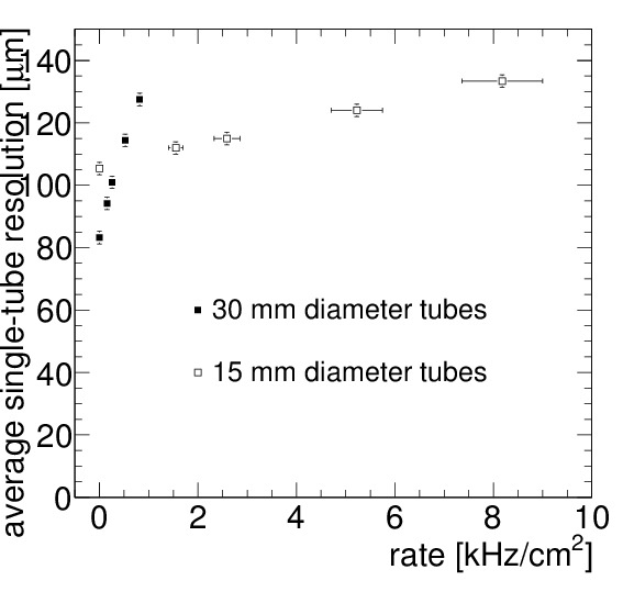
Since the drift-tube spatial resolution at low background rates improves with the drift distance, the average single-tube resolution deteriorates from m for 30 mm diameter tubes [3, 5] to about m for 15 mm diameter tubes. For 30 mm diameter drift-tubes, the resolution has been measured to deteriorate appproximately linearly with the counting rate to about m at 500 Hz/cm2 [3, 5]. For 15 mm diameter tubes, the rate dependence of the resolution, dominated by the gain drop effect, is expected to be about 10 times smaller (see Fig. 1).
3 Chamber design and fabrication
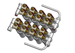
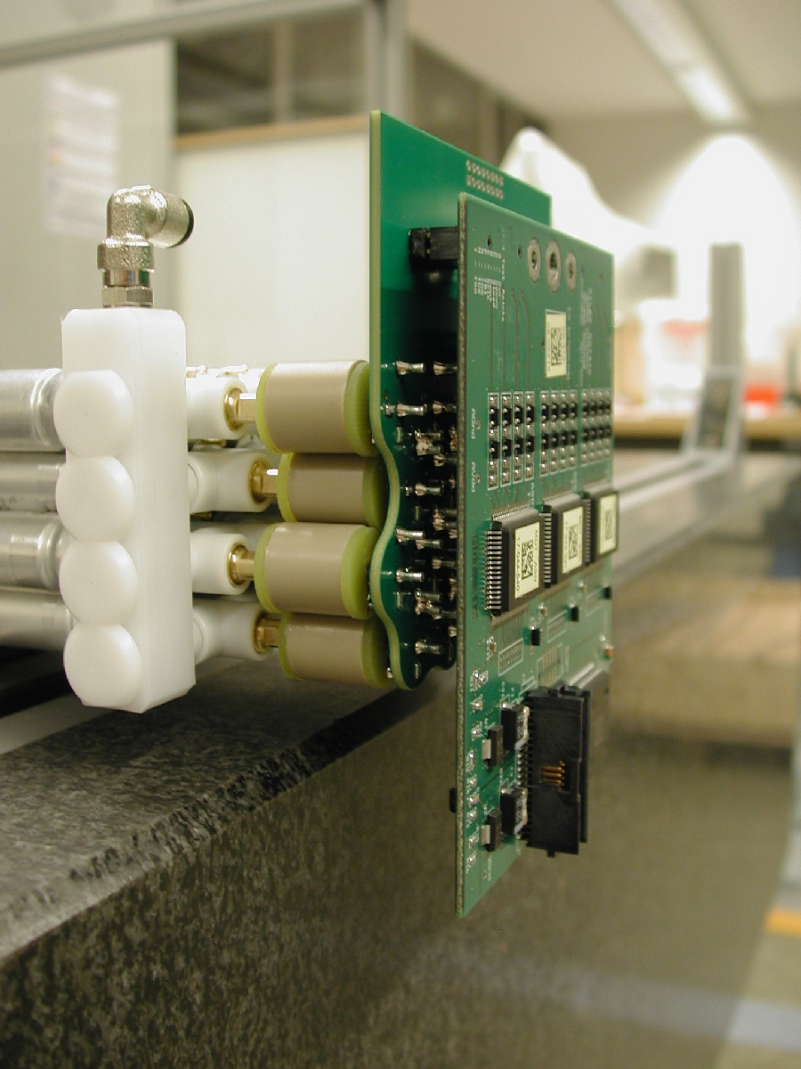
Central to the chamber design is the development of endplugs for the 15 mm diameter tubes (see Fig. 2) which builds on the endplug design for the ATLAS MDT chambers [8]. The injection moulded plastic endplugs electrically insulate the sense wire from the tube wall and center the wire in the tube with few micron accuracy with respect to the external reference surfaces on the central brass inserts of the endplugs. The wire is tensioned and fixed in copper crimp tubelets at the ends of the brass inserts. The endplugs also provide the interfaces to the gas distribution system (see Fig. 3 and to the readout and high-voltage distribution boards (see Fig. 4). Ground pins inserted between adjacent tubes electrically interconnect the tube walls and connect them to ground. The decoupling capacitors on the readout end of the tubes and the protection resistors on the high-voltage connection side are housed in insulating plastic cans.
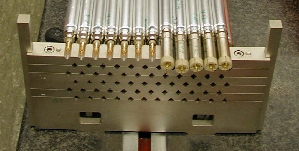
The tubes are assembled to a chamber using precise mechanical jigs (see Fig. 5 positioning the sense wires relative to each other with better than m accuracy using the external reference surfaces of the endplugs. All tubes of a multilayer can be assembled and glued together in a single step requiring only one working day. A prototype chamber consisting of 12 layers with eight one meter long drift tubes has been constructed (see Fig. 5). Standard aluminum tubes with 0.4 mm wall thickness and tolerances of mm on diameter, roundness and concentricity and of mm on straightness have been used successfully. Measurements of the prototype chamber in a cosmic ray test stand with two ATLAS MDT chambers as tracking references [9] confirmed the desired wire positioning accuracy of m.
4 Test results
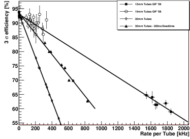
Drift tubes of 15 mm diameter and one meter length equipped with the ATLAS MDT readout electronics [2] have been tested with cosmic ray muons in the Gamma Irradiation Facilty (GIF) at CERN at counting rates of up to 1.85 kHz. The test setup with two MDT reference chambers above and below the tested detectors is described in [10]. The adjustable deadtime of the readout electronics was set to its minimum value of 200 ns. With increasing background counting rate, the muon hits are increasingly masked by background hits. The measured probability to detect a muon hit at the drift radius expected within three times the spatial drift-tube resolution of the extrapolation from the reference chambers is shown in Fig. 6 as a function of the counting rate in comparison with previous measurements for 30 mm diameter drift tubes with the same readout electronics with 200 and 790 ns deadtime setting [3]. The drift-tube efficiency is considerably increased as expected, approximately by the ratio of the sums of the maximum drift time and the electronics dead time.
References
- [1] The ATLAS collaboration, Technical Design Report for the ATLAS Muon Spectrometer, CERN/LHCC 97-22, May 1997.
- [2] The ATLAS collaboration, The ATLAS Experiment at the CERN LHC, JINST 3 S080003 (2008).
- [3] S. Horvat et al., Operation of the ATLAS Precision Muon Drift-Tube Chambers at High Background Rates and in Magnetic Fields, IEEE Trans. on Nucl. Science Instr., Vol. 53, No. 2 (2006) 562.
- [4] M. Aleksa et al., Rate Effects in High-Resolution Drift Chambers, Nucl. Instr. and Meth. A 446 (2000) 435.
- [5] M. Deile et al., Performance of the ATLAS Precision Muon Chambers under LHC Operating Conditions, Nucl. Instr. and Meth. A518 (2004) 65.
- [6] B. Bittner et al., Development of Muon Drift-Tube Detectors for High-Luminosity Upgrades of the Large Hadron Collider, Nucl. Instr. and Meth. A (2009), doi:10.1016/j.nima.2009.06.086.
- [7] W. Riegler, High Accuracy Wire Chambers, Nucl. Instr. and Meth. A494 (2002) 173.
- [8] F. Bauer et al., Construction and Test of the Precision Drift Chambers for the ATLAS Muon Spectrometer, IEEE Trans. on Nucl. Science Instr., Vol. 48, No. 3 (2001) 302; F. Bauer et al., The First Precision Drift Tube Chambers for the ATLAS Muon Spectrometer, Nucl. Instr. and Meth. A478 (2002) 153.
- [9] O. Biebel et al., Test and calibration of large drift tube chambers with cosmic rays, IEEE Trans. on Nucl. Science Instr., Vol. 52 (2005) 2998.
- [10] J. Dubbert et al., Precision Drift Tube Chambers for the ATLAS Muon Spectrometer at Super-LHC, proceedings of the 2008 IEEE Nuclear Science Symposium, Dresden, Germany, 19-25 October 2008, Nuclear Science Symposium Conference Record 2008, IEEE, 2008, MPI report, MPP-2008-191, November 2008.