High pressure research using muons at the Paul Scherrer Institute
Abstract
Pressure, together with temperature and magnetic field, is an important thermodynamical parameter in physics. Investigating the response of a compound or of a material to pressure allows to elucidate ground states, investigate their interplay and interactions and determine microscopic parameters. Pressure tuning is used to establish phase diagrams, study phase transitions and identify critical points. Muon spin rotation/relaxation (SR) is now a standard technique making increasing significant contribution in condensed matter physics, material science research and other fields. In this review, we will discuss specific requirements and challenges to perform SR experiments under pressure, introduce the high-pressure muon facility at the Paul Scherrer Institute (PSI, Switzerland) and present selected results obtained by combining the sensitivity of the SR technique with pressure.
keywords:
muon-spin rotation, pressure, magnetism, superconductivity1 Introduction
Muon spin rotation/relaxation (SR) experiments make use of polarized muons, which thermalized in the sample, act as a magnetic spin microprobe or as a hydrogen-like probe in the host material. Muons provide unique information at local atomic level on physical properties of matter and are used to study a variety of static and dynamic phenomena in superconductivity, magnetism, material science, radical chemistry, semiconductor physics and many other fields. They give information unavailable to other techniques so that muon studies are often complementing those involving other methods. High pressure research has become one of the most significant area in SR and is a major tool in understanding the properties of different phases of matter and their interplay. This is best exemplified in the role of magnetism in many unconventional superconductors, where pressure can drive the system from one state to another and where the specific local information of SR can help to identify on one hand different magnetic states (ordered, short range ordered or disordered) and how they coexist or compete with superconductivity at nanoscale and, on the other hand, to quantify the effects on the strength and structure of superconductivity, such as the determining the superfluid density and the gap symmetry and structure. The importance of this technique has led to the development of dedicated instruments. The instrument called GPD (General Purpose Decay instrument) and the associated beam-line at PSI represent the state of the art of the tools available for pressure studies in SR; to enhance the field of application a continuous effort is being invested in improving the relevant parameters for an experiment such as pressure and temperature range, signal to background level and minimum sample quantity required.
In this review paper we summarize the status of high-presssure studies in SR. The paper is organized as follows. Section 2 gives a short introduction of the SR method. The experimental setup at PSI with the E1 beam line, delivering the energetic positive muons to the GPD spectrometer are described in Sec. 3. The specificities of a SR experiment under pressure are pointed out in this Section 3.2. In Section 4 details of the design of the piston-cylinder pressure cells which are used to apply pressure up to 2.4 GPa to the sample are given. Material considerations and the pressure calibration procedure at low temperature are presented as well. Some scientific examples showing the capabilities of SR under pressure for studying a large variety of phenomena are discussed in Section 5. The paper concludes with a brief outlook about future possible directions of development.
2 Introduction to the SR technique
In this section we give a brief introduction to the SR technique. The interested reader is referred to more comprehensive textbooks [1, 2]. The muon is an elementary particle, positively or negatively charged, with spin 1/2 and lifetime s. SR makes mostly use of the positive muons, which can be produced with very high polarization. Implanted in a solid sample they very quickly thermalize at a generally interstitial position of the lattice where they act as a local magnetic probe. The possibility to use muons as microprobe of matter was predicted already in 1957 in the seminal work of L.R. Garwin et al. reporting about ”Observations of the Failure of Conservation of Parity and Charge Conjugation in Meson Decays: the Magnetic Moment of the Free Muon“ [3], where they recognized the potential of polarized muons and wrote: ”It seems possible that polarized positive and negative muons will become a powerful tool for exploring magnetic fields in nuclei, atoms, and interatomic regions“. Muons are obtained from the decay of positive pions (). At PSI the pions are generated by bombarding two graphite targets with an intense beam of protons with 590 MeV kinetic energy at a present maximum current of 2.2 mA. Because of the parity violating pion decay only left-handed exist so that the decay muons have the spin antiparallel to their momentum in the pion rest frame. This property allows to obtaining polarized beams. Presently, there are worldwide four facilities: PSI (Switzerland) and TRIUMF (Canada), delivering continuous beams and ISIS (UK) and J-PARC (Japan), delivering pulsed beams. In these facilities beam lines have been optimized to transport polarized muons to dedicated instruments where SR experiments under different experimental conditions are performed.
The SR technique is based on the observation of the time evolution of the muon spin polarization of an ensemble of muons after their implantation into a sample (). The direct observation of the muon spin dynamics is possible due to the parity violating muon decay. Positive muons decay into a positron, muon antineutrino and electron neutrino (). The positron is preferentially emitted along the direction of the muon spin at a moment of the decay (decay asymmetry). Thus, by measuring the direction and the timing of a significant number of decay positrons (typically several millions per detector) it is possible to directly follow the time evolution of the polarization of a muon ensemble.
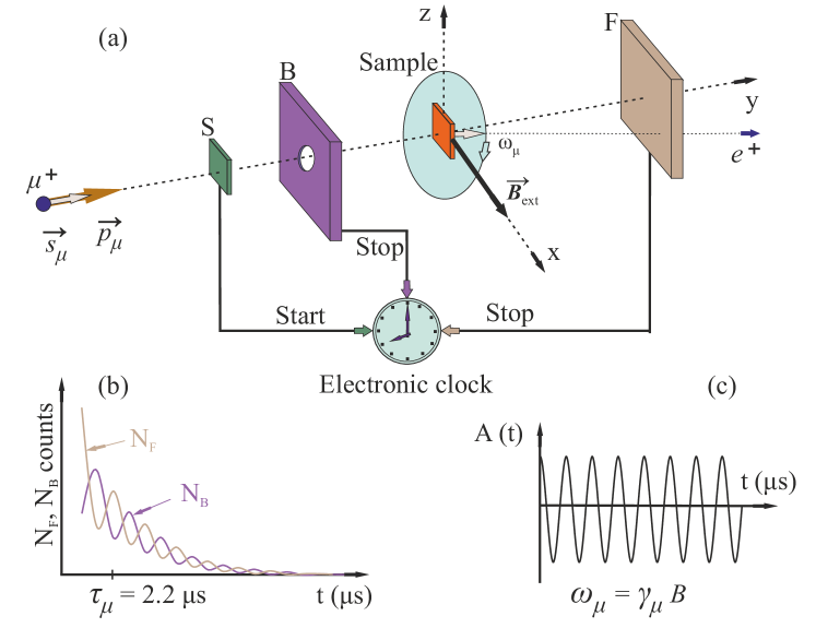
The basic principle of a SR experiment at the high pressure setup at PSI is illustrated in Fig. 1. At the time of the implantation into the sample, a clock triggered by the muon traversing detector S is started. After the very quick thermalization, the muons spin starts to precess with the Larmor frequency ( MHz/T is the gyromagnetic ratio of the muon) in the local magnetic field (vector sum of external and internal magnetic field) until it decays with lifetime of s and emits a positron preferentially in the direction of the spin at the time of decay. The latter is then detected by one of the positron-detectors which stops the clock. Repeating this procedure for several muons, histograms (SR time spectra) are generated. For the initial spin orientation of the muon parallel to its momentum (as is the case for the energetic muons used for pressure studies), the spin rotation/relaxation can be observed using two positron counters mounted on the opposite sides of the sample in the forward and the backward detector(F/B denotes forward/backward with respect to the initial spin direction). The number of positrons detected by each counter as a function of time reflects the time dependence of the muon spin polarisation along the axis of observation defined by the two detectors:
| (1) |
where
| (2) |
is the experimentally observable maximum decayasymmetry at and the average is over the muon ensemble implanted in the sample. Its value depends on the details of the experimental configuration and factors, such as the detector solid angle and efficiency, absorption and scattering of positrons in the material. It typically lies between 0.25 and 0.3, slightly lower than the intrinsic asymmetry of the muon decay, which is 1/3. The signal corresponding to the time evolution of the muon spin polarisation can be directly extracted by looking at the so called asymmetry function , determined as the difference of the signals observed by the two counters, normalised by their sum:
| (3) |
The parameter takes into account the different solid angle and efficiency of the F and B positron-detectors and is calibrated at the beginning of the experiment. The quantities or contain all the information about the interaction of the muon spin (or magnetic moment) with its local environment and provide therefore the physical information about the investigated system.
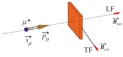
Generally two different magnetic field configurations are used: the transverse-field (TF) and the longitudinal (LF) configuration. In the TF-configuration the external magnetic field is applied perpendicular to the initial muon polarization, whereas in LF-SR the field is applied along the initial muon spin direction (see Fig. 2). The SR experiment can be also performed in zero applied field (ZF).
3 Setup for SR pressure studies
In this section we describe the E1 beam line, delivering high energetic polarized positive muons, and the GPD instrument.
3.1 The E1 beam line
In conventional SR experiments in bulk materials the so-called surface muons are used. They are obtained from pions decaying at rest near the surface of the production target and hence their name. As a consequence of the two-body decay they are fully polarized and have a kinetic energy of 4.1 MeV and a momentum of 29.8 MeV/c, so that beams based on this process are nearly monochromatic and 100% polarized. Their range in matter corresponds to mg/cm2 (e.g. in Cu with density 8.96 g/cm3 this amounts to 0.2–0.3 mm only). To be able to traverse the cell walls and stop in the sample material placed inside a pressure cell, more energetic muons are needed. This is achieved by collecting muons, which are the product of pions decaying in flight, so that the total momentum of the muons is the relativistic vector sum of the pion momentum and of the intrinsic momentum from the decay. The polarization of such a high energy muon beam (decay muon beam line) in the laboratory frame is about 80%.
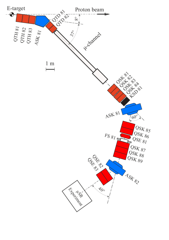
Fig. 3 shows the E1 decay line. The ’beam optics’ consist of magnetic elements to transport and focus the beam (quadrupoles, Q) to the instrument and select the momentum (dipoles A). Slits (F) are used to adjust beam size, intensity and momentum width. Pions produced in the thick target E in the forward direction are extracted at 8∘ and collected over a small solid angle using a triplet of half quadrupoles. The first dipole magnet ASK81 selects the momentum of the pions, which enter a 8 m long decay channel section consisting of a superconducting solenoid with a longitudinal field of T. A large fraction of pions with not too high momentum decay in the channel. In this respect the solenoid may be viewed as an extended muon source. The second and third dipole magnets together with the slit system perform a muon momentum and momentum width selection. Usually, only the muons emitted parallel (forward) or antiparallel (backward) to the muon momentum are selected, in order to obtain a large degree of polarization, which in the laboratory frame is limited to about 80%. Note that opposite to the ’surface‘ muons having spins oriented antiparallel to their momentum, the ’backward‘ muons generally used for pressure E1 have spins parallel to the momentum (see also Figs. 1 and 2). The characteristics of E1 beam line are summarized in Table 1.
| \topruleMomentum acceptance (FWHM) | 3% |
|---|---|
| Pion momentum range [MeV/c] | 200–125 |
| Muon momentum range [MeV/c] | 125–60 |
| Rate of positive muons [mA-1s-1] | |
| Rate of negative muons [mA-1s-1] | |
| Spot size (FWHM) | mm |
| \botrule |
3.1.1 The General Purpose Decay spectrometer (GPD)
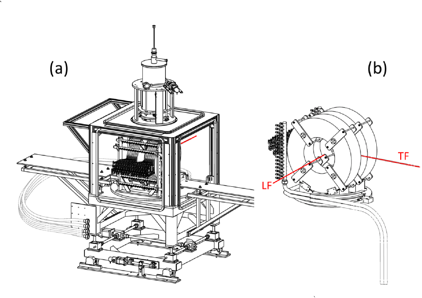
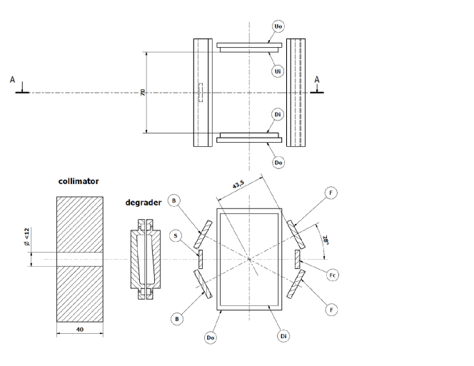
The GPD SR spectrometer (Fig. 4 a) is permanently installed in the E1 area. The instrument is designed to perform SR experiments in zero-field (ZF), longitudinal-field (LF), and transverse-field (TF) in a wide temperature range making use of dedicated cryostats (see Table 2). The GPD spectrometer is equipped with a water cooled Helmoholz coils magnet providing a maximum field T. To select between the longitudinal and the transverse field geometry the magnet can be turned by 90 degrees (Fig. 4 b). Sample rotation is provided for angular dependent studies in single crystals. A plastic degrader can be installed at the entrance to reduce the energy of the incoming muons. The size of the incoming muon beam is defined by passive lead collimators. Cylindrical collimation with 16, 12, 10, 8, or 6 mm and rectangular collimation over mm2 is possible.
| \topruleCryostat | Brand | range | Use with |
|---|---|---|---|
| pressure cells | |||
| \colrule3He Sorption pumped | Oxford | 0.24-325 K | Yes |
| 4He gas flow | Janis | 2.5-300 K | Yes |
| Closed Cycle Refr. | Home made | 10-300 K | No |
| N2 gas flow | Home made | 80-500 K | No |
| \botrule |
The detectors consist presently of plastic scintillators. The detectors are arranged as (i) a muon counter (start detector S, 3.0 mm thick) and (ii) five positron detectors denominated (with respect to the beam direction) Forward (F), Forward center (FC), Backward (B), Up (U), and Down (D) (see Fig. 5). The U and D detectors are divided in two subdetectors (Uo, Ui and Do, Di). Each of the detector is read by a photomultiplier tube (Hamamatsu-PTs R1828-01). The forward center detector can be used in the so-called ”veto“ mode for detecting muons (and their decay positrons) which have not stopped in the sample and rejecting the corresponding events. It is used in experiments without the pressure cell. With the pressure cell installed, when all the muons are stopped in the cell and the sample, the FC detector is combined with the F detector to increase the forward solid angle.
3.2 SR under pressure
The asymmetry function described by Eq. 3 contains the information on the physics of the sample studied. Due to the local character of SR the asymmetry has ”additive“ character, in the sense that muons probing different local magnetic environments will have a distinctive signature each contributing to the asymmetry spectrum:
| (4) |
This property allows to determine volume fractions of different phases and their interaction. For a SR pressure experiment, the measured asymmetry contains the separate contributions of the pressure cell as a background signal and of the sample, which has to be maximized:
| (5) |
(where ’pc’ and ’s’ denote the pressure cell and the sample, respectively).
By tuning the muon momentum, one chooses the value maximizing the ratio between the number of muons stopped inside the sample and the number of the muons stopped in the pressure cell walls (signal to background ratio). As illustrated in Figs. 6 (a) and (b) this ratio depends not only on the muon momentum but also on the lateral extension of the muon beam, which ideally should be as small as possible to reduce the contribution of muons missing the sample while stopping in the cell walls.
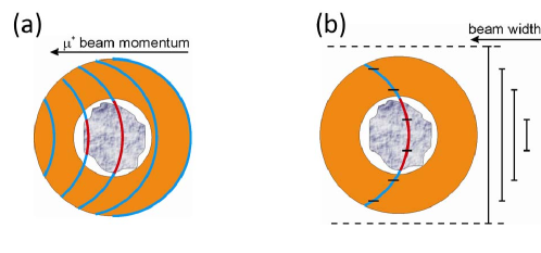
However, the size of the muon beam cannot be arbitrarly reduced. The finite dispersion of the beam momentum has to be convoluted with the ’natural‘ longitudinal and transverse straggling of the muons as a consequence of energy loss and scattering while crossing the shields of the cryostat, pressure cell walls and thermalizing in the sample. These effects amount to a spread of the order of a few millimeters, and limit the minimum possible dimension of the beam spot at the sample. Moreover, the size of the beam is also momentum dependent. Obtaining the optimum values of the beam momentum, which also depends of the particular choice of the pressure cell (see below) is therefore a key operation, which is performed at the beginning of a measuring series. Summarizing:
-
•
Samples of relative large dimensions are required ( 150 mm3) in order to have a sizable signal from the sample inside the pressure cell. This is contrast to other techniques such as resistivity, AC and DC magnetization, specific heat, etc. where samples of less than one mm3 can be measured thus allowing the use of e.g. anvil type of cells.
-
•
At present, the only practical choice for SR experiments are piston-cylinder pressure cells, which provide a reasonable amount of sample space [4]. Development at PSI has concentrated on improving the characteristics of this type of cells within the boundary condition to use them in an existing sample and cryogenic environment (which limits the maximum outer diameter of the pressure cell to about 26 mm).
-
•
Our experimental tests reveal that more than 50% of the muons can be stopped in the sample by using a piston-cylinder pressure cell with mm inner diameter and about 30% for mm cell. On the other hand, mm cells sustain less pressure than the mm ones. Thus the choice of the specific pressure cell will be dictated by the experimental requirements.
4 Pressure cells for SR experiments
Several parameters are determinant to perform successful SR measurements under pressure. The most important are the availability of a large sample volume and hydrostatic pressure conditions. In addition, low temperatures (i.e. sub-Kelvin) are generally required to study several relevant condensed matter topics. Another factor is the possibility to perform pressure scans without actually opening the cell. In addition to the obvious time saving, which is essential when using a costly particle beam, this latter point is important (i) for calibration reasons: each opening of the cell may lead to a slight change of the sample position, and/or cause a redistribution of the sample pieces in case of a multi-parts sample, which would require a new time-consuming calibration; (ii) the physical properties of the sample may change during each fresh pressurization. All the above mentioned points require the use of piston-cylinder pressure cells for which the mechanical properties can be either calculated using the long cylinder theory [4, 5] and/or simulated by using finite element analysis applications (see e.g. Ref. [6] describing pressure cells used for inelastic neutron scattering and Fig. 8 for an example of the PSI double-wall pressure cell open on both sides).
In the following Sections, we will briefly overview the history of SR experiments performed under pressure, describe the design of the pressure cells used at PSI and present the properties of the materials used to build the pressure cell and related accessories.
4.1 SR experiments under pressure – brief historical overview
The first SR experiments under pressure at PSI were performed in 1980 by Butz et al. [7]. A clamped cell with oil as pressure transmitting media (maximum pressure, GPa) was used for studying the transition metals Fe and Ni. As a next step, in 1986 a gas pressure cell was designed ( GPa, Helium as pressure transmitting media) [8, 9]. However, due to safety reasons, the maximum pressure available for these cells was limited to about 0.9 GPa. This type of pressure device was successfully used until 1999 for various studies [8, 9, 10, 11, 12, 13, 14, 15, 16]. In addition to the limited pressure range, these cells had the disadvantage that the Helium capillary imposed quite severe temperature range restrictions, with typical lowest temperatures slightly below 10 K. Moreover, safety reasons imposed a release of the pressure when accessing the experimental area which caused unwanted pressure cycles.
At the beginning of 2001, a new generation of PSI pressure cells came into operation [17]. The starting point was a close collaboration with the group of D. Jaccard from the University of Geneva. A first development was a single layer piston cylinder cell, open solely at one end, using liquid as a pressure transmitting media and made of a Copper Beryllium (CuBe) alloy. The peculiar opening at only one end was adopted because of the restrictions imposed by the sample environment, i.e. the distance between the center of the cryostat windows to the bottom of the sample space. This cell could reach GPa ( GPa) for a 7 mm (5 mm) inner diameter of the cell.
A further step was accomplished with the use of MP35N (Ni-Co-Cr-Mo) alloy for the body of the pressure cell and pressures up to about 1.9-2.0 GPa could be routinely obtained. The latest developments are double layer cells made of a combination between CuBe and MP35N. To guarantee a SR signal with a high enough signal to background ratio, the dimensions of the sample space are rather large limiting therefore the maximum pressure to 2.5 GPa (1.8 GPa) for a sample space with a diameter of 6 mm for pressure cells opened from both sides made out of MP35N/MP35N (or CuBe/CuBe, respectively). This type of cells will be presented in more details in Section 4.2.
It is fair to say that presently the bulk of SR experiments under pressure, as well as of the further development of SR pressure cells are performed at PSI. This is due to the unique combination of high-pressures and sub-Kelvin croygenics capabilities available at the GPD instrument. Nevertheless, some activity takes place also at ISIS (UK) and at TRIUMF (Canada). At ISIS the experiments are carried out using the high-momentum RIKEN-RAL beamline by using gas pressure cell with GPa [18, 19, 20, 21, 22, 23, 24]. At TRIUMF a single wall piston-cylnder type of pressure cell with maximum pressure GPa is used. The experiments are conducted at the M9B beam-line by using the dedicated ‘Omni-Prime’ spectrometer.
4.2 Double-wall cells used at PSI
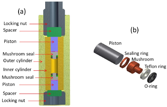
The cross-sectional view of a fully assembled typical double-wall pressure cell is presented in Fig. 7. The main components of the cell are: (i) a cylindrical double-wall body, (ii) pistons, (iii)’mushroom‘ seals, (iv) locking nuts, and (v) spacers. The latest are needed to support the pistons and prevent their rotation when the nuts are tightened. Diameters and heights of the outer and the inner cylinders are mm, mm, and mm, mm, respectively. Two types of cells with inner diameter 6 mm and 7 mm were produced. With both pistons completely inserted, the maximum sample height is mm. The body of the cell, the top and the bottom locking nuts and the mushroom pieces are made of MP35N alloy (Ni – 35%, Co – 35%, Cr–20%, and Mo–10% in weight percent, see Ref. [25]). All the pieces were heat-treated for 4 hours at 590 oC after machining. Pistons and spacers are made of non-magnetic tungsten carbide (ceratizit-ctf21r, see Ref. [26]). The sealing rings were made of fully hardened Copper Beryllium alloy (berilco-25).
The body of the pressure cell consists of two parts – the inner and the outer cylinders which are shrink fitted into each other. Two alternative methods for the fabrication of the pressure cell were tried. In the first approach, the inner cylinder was prepared with a diameter mm bigger than the inner diameter of the outer cylinder. By heating the outer cylinder up to C and cooling down the inner one to liquid nitrogen temperature it is possible to fit them into each other. By coming back to ambient temperatures the inner cylinder remains under radial compression from the outer cylinder. In the other approach, the outer surface of the inner and the inner surface of the outer cylinders were machined conically with the angle of . The diameter difference of both fully assembled cylinders is mm. The pressure cell is produced by mechanically inserting the inner cylinder into the outer one by using a hydraulic press. This process is similar to the situation of a cold/warm fitting of the cylinders as described above. The friction between the two parts is high enough to keep the cell fully assembled. Note that pressure cells produced by both described ways were found to behave very similarly with respect to the the maximum reachable pressure, as well as with respect to the pressure loss caused by friction between the sealing system and the pressure cell walls.
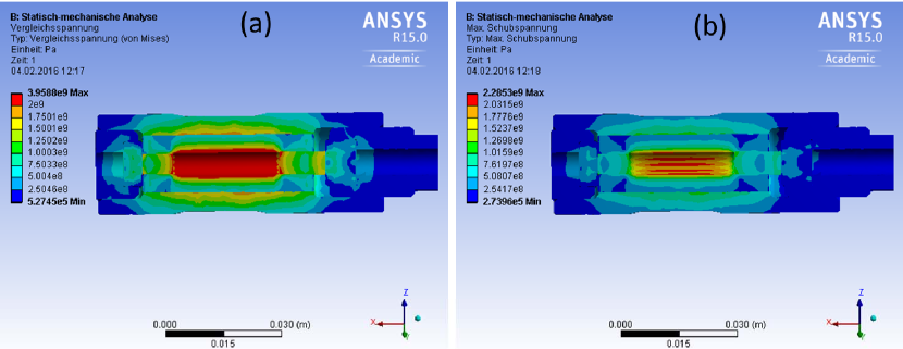
In order to investigate the mechanical response of the cell to the applied pressure, a finite element analysis by using the ansys r15.0 software was performed [27] using the appropriate boundary conditions and including a modeling of the force between two cylinders. Figure 8 shows a sectional view of the body of the cell with the corresponding principal stress and the shear stress distributions. These calculations were made for ‘extreme’ conditions, i.e. when the stress at the border between two cylinders reaches the so-called ultimate tensile strength of the MP35N alloy (2.07 GPa, Ref. [25]). The results reveal that the ‘theoretical’ limit for a double-wall cell made of MP35N alloy is of the order of 3.9 GPa. For safety reasons, the maximum applied pressure is always limited to 3.5 GPa. The applied pressure at closing time is calculated as , where is the force applied by the hydraulic press and is the surface area of the piston. Note that is usually much larger than the effective real pressure inside the cell due to friction effects.
As will be shown later for K, the SR response of a MP35N cell is strongly temperature dependent. Therefore, at very low temperature, the cell signal may be difficult to separate from the one of the sample. For precise experiments we have also prepared a single wall pressure cells of a similar design (as in Fig. 7) made of Copper Beryllium alloy. Even though such a cell allows to reach a maximum pressure just half of the one accessible with a double wall MP35N cell, the paramount advantage of it is a SR response that is temperature independent at very low temperatures.
4.3 Pressure seal design
The design of the seal is defined by two requirements. First, as shown in Section 3.2, in SR experiments under pressure the muons stop not only in the sample but also in the pressure cell walls. Therefore, the muon asymmetry spectra described by Eq. 5 consists of ‘sample’ and ‘pressure cell’ contributions and one should avoid the presence of any other material, except the sample, inside the pressure cell channel. A second requirement is to have the possibility to perform several pressure changes without opening the pressure cell.
We approached the problem by implementing the seal shown in Fig. 7b. The seal assembly consists of a conically shaped sealing ring (hardened Copper Beryllium), a mushroom-shaped piece (MP35N alloy), a teflon ring and a rubber O-ring. The initial sealing is made by the O-ring allowing one to close the cell and to increase the pressure up to the level where the teflon ring starts to flow and to fill the gap between the mushroom and the pressure cell walls. The conical Copper Beryllium ring impedes that the teflon flows further which would cause a blocking of the piston. This design makes full use of the bore of the cell to accommodate the sample, and allows to perform repeated pressure changes in increasing or decreasing directions.
4.4 Pressure cell loading, pressure determination and pressure loading curve
The process of loading the cell is permanently monitored by using a specially designed computer-controlled system allowing to measure in-situ the displacement of the piston () and the radial expansion of the pressure cell as a function of loading force . Special attention is paid to maintain the pressure cell in the ‘elastic’ regime, i.e. by ensuring that the slope of the loading curve is almost constant. A sudden change of the slope would correspond either to a leakage of the cell or would signal that one exceeds the local stress level above the elastic regime. In both cases the loading process must be immediately stopped and the pressure in the cell released to zero.
The exact pressure inside the cell is determined by monitoring the pressure-dependent shift of the superconducting transition temperature () of a small piece of Indium (pressure probe). The volume of the pressure probe is much lower than the one of the sample to avoid an additional background contribution to SR signal. For the superconducting transition temperature of Indium the following relation holds [28]:
| (6) |
where K is the transition temperature of In at ambient pressure.
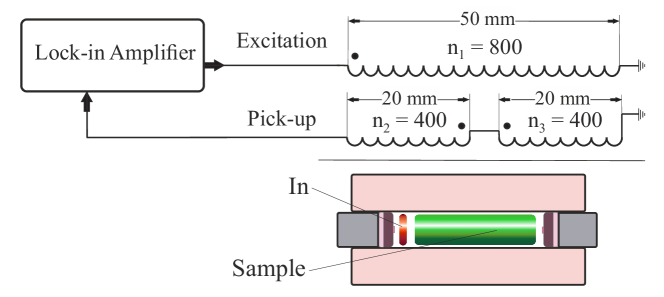
The superconducting transition of the pressure probe is determined by AC susceptibility measurements. A coil surrounding the pressure cell (input coil) is fed with an AC current. A second coil, inside the first one, made up of two sub-coils (one centered at the position of the pressure probe) wound in opposition is used as pick-up coil. The signal of the pick-up coil is compensated above but becomes uncompensated when the superconducting transition is crossed upon lowering the temperature. The lack of compensation is detected using a lock-in amplifier which compares the phase and amplitudes of the input signal with the ones of the pick-up signal (see Fig. 9). Note, that the pressure is determined at temperatures corresponding to of Indium (i.e. K). By performing experiments at higher temperatures one needs to consider the temperature dependent pressure drop of the pressure transmitting medium (see e.g. Ref. [29] and references therein).
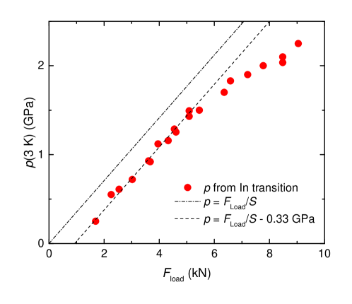
The measured pressure at low temperatures inside the cell is shown as a function of the load in Fig. 10. The dash-dotted line is the ideal pressure . Up to the pressure of GPa the difference between the ideal curve and the measured data is constant ( GPa) and it is entirely determined by temperature compression of the pressure transmitting medium (Daphne 7373 oil in this case). At higher loads frictional effects become noticeable. At a pressure of GPa the difference between the ideal and the determined pressure is GPa. Part of it (0.33 GPa) is due to the temperature induced compression of the pressure transmitting medium, while GPa is caused by friction.
4.5 SR background signal caused by the pressure cell body
The Copper Beryllium and MP35N alloys were used to build the body of the pressure cell, both because of their strength and their well-defined background contributions to the SR signal.
4.5.1 Copper Beryllium
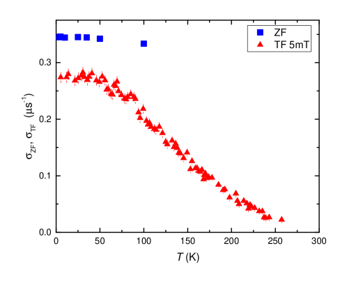
Copper Beryllium (berilco-25) is a nonmagnetic alloy down to at least 250 mK. Muons implanted in Copper Beryllium sense solely the magnetic field distribution created by the nuclear magnetic moments which can be considered static within the SR time-window. Within these conditions, the zero-field (ZF) SR spectra obtained on an empty cell made of Copper Beryllium can be fitted with a so-called Kubo-Toyabe depolarization function [30]:
| (7) |
where represents the second moment of the field distribution along one cartesian axis perpendicular to the initial muon polarization. The temperature dependence of is reported in Fig. 11.
The contribution of the cell in transverse-field (TF) experiments, where the external field is applied perpendicular to the initial muon-spin polarization, is well described by a Gaussian depolarization function:
| (8) |
Here is a phase shift determined by the initial muon-spin polarization with respect to the detectors geometry. The second moment of the field distribution along the direction of the external field is given by . The temperature dependence of measured with an applied field mT is presented in Fig. 11.
4.5.2 MP35N alloy
The alloy MP35N is nonmagnetic down to low temperatures, but its SR response depends strongly on the applied field (see Ref. [31]). Muons implanted in MP35N sense both the static magnetic field distribution created by the nuclear magnetic moments and a dynamical field distribution created by the electronic moments in the paramagnetic phase. The ZF SR spectra measured in the MP35N alloy is therefore fitted by a Kubo-Toyabe depolarization function multiplied by an exponential damping:
| (9) |
Here and are the static (nuclear) and the dynamic (electronic) relaxations rate, respectively. Results of ZF test experiments are presented in Fig. 12 (a). The depolarization rate is small down to 1 K then increases abruptly upon decreasing the temperature, signaling a slowing down of the fluctuations and indicating that correlations between the electronic moments start to build-up however without magnetic ordering down to 0.26 K, see Fig. 12 (b). This behavior may set some limitations for the use of MP35N pressure cells below 1 K.
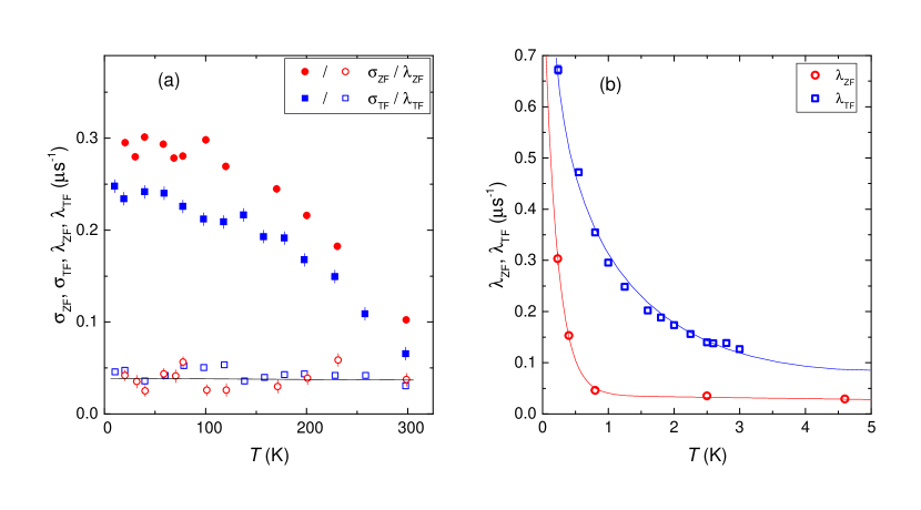
In TF experiments the pressure cell contribution is analyzed by using the following functional form:
| (10) |
Temperature dependences of and are presented in Fig. 12. Experience showed that different parts of the MP35N rods, from which the pressure cell parts are produced, have slightly different chemical compositions and/or homogeneity, leading to slightly different depolarization rates. Hence, accurate SR characterization measurements need to be performed separately for each particular pressure cell made of MP35N alloy.
4.6 Pressure transmitting medium
Hydrostaticity at low temperature is the key feature for a liquid used as a pressure transmitting medium (PTM). The reason is that a hydrostatic pressure is a thermodynamic parameter and the results obtained under such conditions can readily be compared with theory. The most commonly used PTM’s are either mixtures of 1:1 isopentane/n-pentane; 4:6 light oil/n-pentane; 1:1 and 5:1 isoamyl alcohol/n-pentane; 4:1 ethanol/methanol; 1:1 Fluorinerts FC72/FC84, FC84/FC87 and FC75/FC77; or ‘single’ phase liquids like Daphne (7373, 7474 and 7575) oils, various Silicone oils and isopentane. Among them, the mixtures of isoamyl alcohol/n-pentane and ethanol/methanol as well as the Daphne oils 7474 or 7575 remain hydrostatic at room temperature up to pressures GPa, which is about the physical limit for the highest reachable pressure using piston-cylinder cells [4, 33]. The other PTM’s are solidifying at lower pressures. Comprehensive studies of these and other PTM’s, with a special attention payed on the effects of non-hydrostaticity at high and low temperatures, are presented in Refs. [4, 34, 35, 29].
For our SR experiments under pressure either Daphne 7373 oil or a 1:1 mixture of n-pentane/isoamyl alcohol are commonly used. Daphne oil is easier to manipulate due to its higher viscosity and lower toxicity. When hydrostaticity at higher pressures is needed, alcohol mixtures are recommended, but special care should be given to the preparation of the pressure cells in order to avoid leakage as these mixtures have a low viscosity.
5 Scientific examples
Muon spin rotation/relaxation is been widely applied to magnetic materials due to the high sensitivity of the muon to small fields and its capability to probe both static and dynamic local field distributions. ZF SR is used to investigate microscopic magnetic properties of solids [30, 36, 37, 38]. It is also valuable for studying materials in which magnetic order is random or of short range. Moreover, SR is very helpful to study samples containing multiple phases or samples which are partially magnetically ordered. This is because muons stop uniformly throughout a sample, and the amplitudes of the SR signals arising from the different regions of the sample are proportional to the volume of the sample occupied by a particular phase. Thus, SR provides quantitative information on coexisting and competing phases in a material.
The SR technique provides a powerful tool to measure the important length scales of superconductors, namely the magnetic penetration depth and the coherence length [39]. A SR experiment in the vortex state [40] of a type II superconductor allows one to determine in the bulk of the sample, in contrast to many techniques that probe only near the surface. is one of the fundamental parameters of a superconductor, since it is related to the superfluid density via 1/ = (where is the effective mass of the superconducting carriers). Most importantly, the temperature dependence of is particularly sensitive to the topology of the SC gap.
In addition to studies of the ideal periodic array of vortices in clean samples, SR has been shown to be a unique microscopic probe of vortex fluctuations, pinning, flux-lattice melting, and the decomposition of flux lines into two-dimensional “pancake” vortices [41, 42, 43, 44]. One can also probe vortices at the surface of a superconductor using ultra-low energy muons [45].
In the following,a few selected experimental results obtained by performing SR experiments under pressure are presented. For further details and examples we refer to the textbooks [1, 2] and original articles [46, 47, 48, 49, 50, 51, 52, 53, 54, 55, 56, 57, 58, 59].
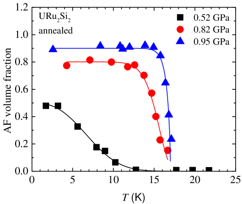
5.1 Pressure induced magnetic order in the heavy-fermion URu2Si2
The heavy-fermion compound URu2Si2 exhibits two successive phase transitions at 17.5 and 1.4 K. Whereas the transition at 1.4 K signals the occurrence of unconventional superconductivity, the phase transition at = 17.5 K remains mysterious. Different scenarios have been invoked concerning the true nature of the phase below . Models suggest that the observed anomalies are not related to the magnetic state, but is rather associated with a hidden order parameter.
In view of its ability to detect different magnetic responses, SR studies under applied hydrostatic pressure up to = 1.5 GPa were performed [60, 61]. The main finding was the observation of spontaneous muon spin precession in zero applied magnetic field at pressures above about 0.5 GPa, clearly indicating spontaneous magnetic ordering of the magnetic moments in the sample. As shown in Fig. 13, the magnetic volume fraction is strongly pressure dependent and starts increasing at temperatures lower than . A fully magnetised sample is obtained for pressures of 1 GPa. Due to the possibility to obtain independently a measure of the magnetic volume and of the magnetic moment, in this context the SR data provided a much clearer point of view. In addition, from the observed behaviour under pressure, it was demonstrated that the superconducting and magnetic states are not coupled but rather phase separated with almost degenerate condensing energies.
5.2 Direct observation of the quantum critical point in the heavy fermion CeRhSi3
A drastic and monotonic suppression of the internal fields in the noncentrosymmetric heavy fermion antiferromagnet CeRhSi3 was observed upon increasing the external pressure [58]. At 2.36 GPa, the ordered magnetic moments are fully suppressed via a second-order phase transition, and is zero, providing direct evidence of the quantum critical point hidden inside the superconducting phase of CeRhSi3.
5.3 Pressure Induced Static Magnetic Order in Superconducting FeSe1-x
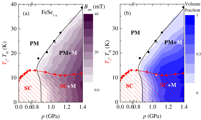
A detailed study of the evolution of the superconducting and magnetic properties of FeSe1-x as a function of pressure and temperature through a combination of AC susceptibility and muon-spin rotation (SR) techniques were recently performed [62, 63, 64]. The obtained phase diagram (see Fig. 14) of FeSe1-x was found to be separated onto three distinct regions. At low pressures, GPa, the samples are nonmagnetic and increases monotonically with increasing pressure. In the intermediate pressure region, GPa, decreases with increasing pressure and the static magnetism develops. In this region of the phase diagram the superconducting and the magnetic order parameters coexist and compete on a short length scale. Incommensurate magnetic order which sets in above , becomes partially (or even fully) suppressed below . At higher pressures, GPa, shows a tendency to rise again. The magnetic order becomes commensurate and both, the bulk magnetism and the bulk superconductivity coexist within the whole sample volume. This exceptional observation provided a new challenge for theories describing the mechanism of high temperature superconductivity.
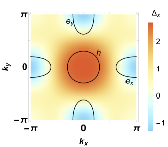
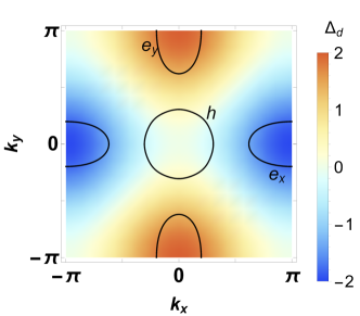
5.4 Direct evidence for a pressure induced nodal superconducting gap in the Ba0.65Rb0.35Fe2As2 superconductor
In contrast to other unconventional superconductors, in the Fe-HTSs both -wave and extended -wave pairing symmetries are close in energy. Probing the proximity between these very different superconducting states and identifying experimental parameters that can tune them is of central interest.
The zero-temperature magnetic penetration depth and the temperature dependence of were studied in optimally doped Ba0.65Rb0.35Fe2As2 by means of SR experiments as a function of pressure up to 2.25 GPa [52]. The superconducting transition temperature stays nearly constant under pressure, whereas a strong reduction of is observed, possibly related to the presence of a putative quantum critical point. The main finding is the observation that pressure promotes a nodal SC gap in Ba0.65Rb0.35Fe2As2. Model calculations favor a -wave over a nodal -wave pairing as the origin for the nodal gap (see Fig. 15).
5.5 Pressure-induced electronic phase separation of magnetism and superconductivity in CrAs
At ambient pressure CrAs is characterized by a relatively high Néel temperature K [65, 66, 67, 68]. decreases approximately by a factor of three for pressures () approaching GPa, above which the magnetism completely disappears [65, 66]. On the other hand superconductivity sets in for pressures exceeding GPa thus revealing a range of GPa where superconductivity and magnetism coexist.
In view of its ability to provide an additional microscopic point of view of the magnetic and the superconducting properties of CrAs SR studies under applied hydrostatic pressure were performed [69]. The obtained results suggest that the pressure-induced transition of CrAs from a magnetic to a superconducting state is characterized by a separation in macroscopic size magnetic and superconducting volumes. The less conductive magnetic phase provides additional carriers (doping) to the superconducting parts of CrAs. This would naturally explain the substantial increase of both, the transition temperature (from 0.9 K to 1.2 K) and the superfluid density (up to %), in the phase coexistence region.
5.6 Tuning of competing magnetic and superconducting phase volumes in LaFeAsO0.945F0.055 by hydrostatic pressure
It was found that the application of pressure leads to a substantial decrease of the magnetic ordering temperature and a reduction of the magnetic phase volume and, at the same time, to a strong increase of the superconducting transition temperature and the diamagnetic susceptibility [46]. It was also concluded that the superconducting and the magnetic areas which coexist in the same sample are inclined towards spatial separation and compete for phase volume as a function of pressure.
5.7 Superfluid density and superconducting gaps of RbFe2As2 as a function of hydrostatic pressure
Using SR the ratio of the superfluid density to the superconducting transition temperature = 2.52(2) K at ambient pressure was determined and found to be much larger in the strongly hole-overdoped RbFe2As2 than in high- Fe-based and other unconventional superconductors [51]. As a function of pressure decreases with a rate of d/d = -1.32 K GPa-1, i.e. it is reduced by 52 at GPa. The temperature dependence of is best described by a two gap -wave model with both superconducting gaps being decreased by hydrostatic pressure until the smaller gap completely disappears at = 1 GPa.
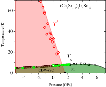
5.8 Strong enhancement of conventional superconductivity near a quantum critical point of (Ca,Sr)3Ir4Sn13
The (Ca1-xSrx)3Ir4Sn13 system displays superconductivity and a structural phase transition associated with the formation of a charge density wave (CDW). SR studies as a function of pressure revealed a strong enhancement of the superfluid density and the of pairing strength above a pressure of 1.6 GPa giving direct evidence of the presence of a quantum critical point separating a superconducting phase coexisting with CDW (see Fig. 16) from a pure superconducting phase [53]. The superconducting order parameter in both phases has the same -wave symmetry. Based on the dependence of the effective superfluid density on the critical temperature, it was suggested that the conventional BCS superconductors in the presence of competing orders or multi-band structure can also display characteristics of unconventional superconductors.
5.9 Effect of pressure on the Cu and Pr magnetism in Nd1-xPrxBa2Cu3O7 investigated by muon spin rotation
A positive pressure effects on the Néel temperatures of both copper and praseodymium were found for Nd1−xPrxBa2Cu3O7 for the whole range of Pr concentrations (0.3 1) [32]. These findings clarify some of the puzzles related to the effect of pressure on superconductivity and magnetism in the praseodymium-substituted hole-doped cuprate systems.
5.10 Tuning the static spin-stripe phase and superconductivity in La2-xBaxCuO4 ( = 1/8) by hydrostatic pressure
An unusual interplay between static spin-stripe order and bulk superconductivity was observed in La2-xBaxCuO4 ( = 1/8) [54]. With increasing pressure the spin order temperature and the size of the ordered moment are not changing significantly. However, application of hydrostatic pressure leads to a remarkable decrease of the magnetic volume fraction (0). Simultaneously, an increase of the SC volume fraction (0) occurs. Furthermore, it was found that (0) and (0) at all are linearly correlated: (0) + (0) 1. These results provide evidence for a competition between bulk superconductivity and static magnetic order in the stripe phase.
5.11 Muon spin rotation investigation of the pressure effect on the magnetic penetration depth in YBa2Cu3Ox
The pressure dependence of the superfluid density as a function of the superconducting transition temperature is found to deviate from the usual Uemura line [56]. The ratio (/)/((0)/) is factor of 2 smaller than that of the Uemura relation. In underdoped samples, an increase of the coupling strength with pressure was also found. In the same work, a special model was also reported for analyzing the SR spectra of samples with strong magnetic moments in a pressure cell.
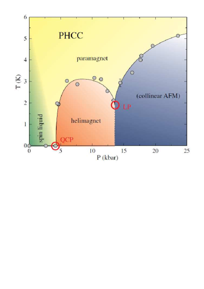
5.12 Pressure-Induced Quantum Critical and Multicritical Points in a Frustrated Spin Liquid
Using high-pressure SR technique the () phase diagram was established for the quantum spin-liquid compound (C4H12N2)Cu2Cl6 [57]. At low temperatures, pressure-induced incommensurate magnetic order is detected beyond a quantum critical point at 0.43 GPa. An additional phase transition to a commensurate magnetic order is observed at 1.34 GPa. The obtained () phase diagram reveals the corresponding pressure-induced multicritical point at , = 2.0 K.
5.13 Evolution of magnetic interactions in a pressure-induced Jahn-Teller driven magnetic dimensionality switch
Pressure induced transition from a quasi-two-dimensional to a quasi-one-dimensional antiferromagnetic phase at 0.91 GPa, driven by a rotation of the Jahn-Teller axis, was observed in the coordination polymer CuF2(H2O)2 (pyrazine) [59]. Long-range antiferromagnetic ordering is seen in both regimes, as well as a phase separation in the critical pressure region. The magnetic dimensionality switching as pressure is increased is accompanied by a halving of the primary magnetic exchange energy and a fivefold decrease in the ordering temperature .
6 Outlook
In this review paper we have summarized the status of high-presssure research at the Paul Scherrer Institute (Switzerland) by means of muon-spin rotation/relaxaton techniques.
Further possible development may be classified along two lines. The first relates to the upgrade of the GPD spectrometer itself. A new detector system consisting of plastic scintillators read-out by Geiger-mode Avalanche Photodiodes (APD)[70, 71, 72, 73, 74, 75] is planned to be installed in the next few years. The use of APD’s, which are not sensitive to magnetic fields and do not require the usage of long light guides, allows to build a very compact detector system with an optimized detectors geometry thus improving the signal to background ratio. The second part relates to the improvement of the SR pressure cells. This includes: (i) the search for new materials suitable (from the background point of view) for SR experiments, (ii) the investigation of new pressure cell designs (as the McWhan-type of cell [4], three wall cells, etc. ), and (iii) the possible use of anvil pressure cells. Our preliminary measurements by using Boron-Nitride anvils from te Paris-Edinburgh cell [4] reveal that enough muons (up to %) could stop into the sample therefore opening a new era of novel SR experiments.
References
- [1] Yaouanc A, de Réotier PD. Muon Spin Rotation, Relaxation, and Resonance. Oxford Science Publications, 2011.
- [2] Schenck A. Muon Spin Rotation Spectroscopy: Principles and Applications in Solid State Physics. Adam Hilger, Bristol, 1985.
- [3] Garwin RL, Lederman LM, Weinrich M. Observations of the Failure of Conservation of Parity and Charge Conjugation in Meson Decays: the Magnetic Moment of the Free Muon. Phys Rev. 1957;105:1415.
- [4] Klotz S. Techniques in high pressure neutron scattering. Boca Raton, FL:CRC Press, 2013.
- [5] Eremets MI. High Pressure Experimental Methods. Oxford University Press, 1996.
- [6] Wang W, Sokolov DA, Huxley AD, Kamenev KV. Large volume high-pressure cell for inelastic neutron scattering. Rev Sci Instrum. 2011;82:073903.
- [7] Butz T, Chappert J, Dufresne JF, Hartmann O, Karlsson E, Lindgren B, Norlin LO, Podini P, Yaouanc A. The effect of pressure on the positive muon spin precession in iron and nickel. Phys Lett A. 1980;75:321.
- [8] Butz T, Kalvius GM, Lindgren B, Hartmann O, Wäppling R, Karlsson E. A high pressure, low temperature system for SR studies, Hyp Interact. 1986;32:881.
- [9] Kratzer A, Mutzbauer K, Heuneberger S, Kalvius GM, Hartmaun O, Wäppling R, Klauß HH, de Melo MAC, Litterst EJ, Stammler T. High pressure SR studies, Hyp Interact. 1994;87:1055.
- [10] Hartmann O, Karlsson E, Wappling R, Asch L, Henneberger S, Kalvius GM, Kratzer A, Klauß HH, Litterst FJ, De Melo MAC. The spin turning in ferromagnetic Gd studied by positive muons, Hyp Interact. 1994;85:251.
- [11] Wäckelgård E, Hartmann O, Karlsson E, Wappling R, Asch L, Kalvius GM, Chappert J, Yaouanc A. Knight Shifts and Relaxation in Gadolinium above the Curie Temperature. Hyp Interact. 1986;31:325.
- [12] Schreier E, Heuneberger S, Burghart EL, Kratzer A, Kalvius GM, Hartmann O, Ekström M, Wäippling R. High pressure SR studies on single crystalline gadolinium. Hyp Interact. 1997;104:311.
- [13] Schreier E. PhD Thesis, TU Münich, (1999).
- [14] Martin EM. PhD Thesis, TU Münich, (1996).
- [15] Martin EM, Schreier E, Kalvius GM, Kratzer A, Hartmarm O, Wäppling R, Noakes DR, Krop K, Ballou R, Deportes J. Magnetic properties of GdMn2 from SR. Physica B 2000;289:265.
- [16] Kalvius GM, Schreier E, Ekström M, Hartmann O, Henneberger S, Kratzer A, Wäppling R, Martina E, Burghart FJ, Ballou R, Deportes J, Niedermayer Ch. High pressure SR studies: rare earths and related materials, Hyp Interact. 2000;128:275.
- [17] Andreica D. Ph. D. Thesis, IPP/ETH-Zürich, 2001.
- [18] Watanabe I, Ishii Y, Kawamata T, Suzuki T, Pratt FL, Done R, Chowdhury M, Goodway C, Dreyer J, Smith C, Southern M. Development of a gas-pressurized high-pressure SR setup at the RIKEN-RAL Muon Facility. Physica B. 2009;404:993.
- [19] Telling MTF, Knight KS, Pratt FL, Church AJ, Deen PP, Ellis KJ, Watanabe I, Cywinski R. Pressure-dependent spin fluctuations and magnetic structure in the topologically frustrated spin glass alloy Y(Mn0.95Al0.05)2. Phys Rev B. 2012;85:184416.
- [20] Ellis KJ, Cywinski R, Pratt FL, Telling MTF. Pressure Dependent Magnetism in Y1.05(Mn0.95Al0.05)2. Physics Procedia 2012;30:198.
- [21] Enomoto M, Kida N, Kojima N, Watanabe I, Suzuki T, Ishii Y. Study on the pressure induced charge transfer phase transition in (C5H11)4N(FeIIFeIII(C2O2S2)3) by means of SR spectroscopy. Polyhedron 2011;30:3137.
- [22] Suzuki T, Watanabe I, Yamada F, Yamada M, Ishii Y, Kawamata T, Goto T, Tanaka H. Pressure-induced new magnetic phase in Tl(Cu0.985Mg0.015)Cl3 probed by muon spin rotation. J Phys: Conference Series 2010;225:012054.
- [23] Suzuki T, Watanabe I, Yamada F, Ishii Y, Ohishi K, Risdiana, Goto T, Tanaka H. Pressure effect on magnetic ground states in Tl(Cu1-xMgx)Cl3 with = 0.015 probed by muon-spin-rotation. J Phys: Conference Series 2010;200:022061.
- [24] Suzuki T, Watanabe I, Yamada F, Ishii Y, Ohishi K, Risdiana, Goto T, Tanaka H. Evidence for continuous change of spin states between impurity-induced order and pressure-induced order in TlCu0.985Mg0.015Cl3 probed via muon spin rotation. Phys Rev B. 2009;80:064407.
- [25] https://www.cartech.com/ssalloysprod.aspx?id=1926
- [26] http://www.ceratizit.com/
- [27] http://www.ansys.com/
- [28] Eiling A, Schilling JS. Pressure and temperature dependence of electrical resistivity of Pb and Sn from 1-300 K and 0-10 GPa-use as continuous resistive pressure monitor accurate over wide temperature range; superconductivity under pressure in Pb, Sn and In. J Phys F: Met Phys. 1981;11:623.
- [29] Torikachvili MS, Kim SK, Colombier E, Budko SL, Canfield PC. Solidification and loss of hydrostaticity in liquid media used for pressure measurements. arXiv:1512.00087.
- [30] Kubo R, Toyabe T. A stochastic model for low field resonance and relaxation, Magnetic resonance and relaxation. North-Holland, Amsterdam, 1967;810-823.
- [31] Walker IR. Nonmagnetic piston-cylinder pressure cell for use at 35 kbar and above. Rev Sci Instrum. 1999;70:3402.
- [32] Maisuradze A, Graneli B, Guguchia Z, Shengelaya A, Pomjakushina E, Conder K, Keller H. Effect of pressure on the Cu and Pr magnetism in Nd1-xPrxBa2Cu3O7-δ investigated by muon spin rotation. Phys Rev B. 2013;87:054401.
- [33] Uwatoko Y, Todo S, Ueda K, Uchida A, Kosaka M, Mori N, Matsumoto T. Material properties of Ni-Cr-Al alloy and design of a 4 GPa class non-magnetic high-pressure cell. J Phys: Condens Matter 2002;14:11291.
- [34] Klotz S, Chervin JC, Munsch P, Le Marchand G. Hydrostatic limits of 11 pressure transmitting media. J Phys D: Appl Phys. 2009;42:075413.
- [35] Tateiwa N, Haga Y. Evaluations of pressure-transmitting media for cryogenic experiments with diamond anvil cell. Rev Sci Instrum. 2009; 80:123901.
- [36] Major J, Mundy J, Schmolz M, Seeger A, Döring K, Fürderer K, Gladisch M, Herlach D, Majer G. Zero-field muon spin rotation in monocrystalline chromium. Hyperfine Interactions 1986;31:259.
- [37] Amato A. Heavy-fermion systems studied by SR technique. Rev Mod Phys. 1997;69:1119.
- [38] Dalmas de Réotier P, Yaouanc A. Muon Spin Rotation in Magnetic Materials. J Phys: Cond Matt. 1997;9:9113.
- [39] Tinkham M. Introduction to Superconductivity. Krieger Publishing company, Malabar, Florida 1975.
- [40] Abrikosov AA. Zh Eksp Teor Fiz. 1950;32:1064.
- [41] Lee SL, Zimmermann P, Keller H, Warden M, Savić IM, Schauwecker R, Zech D, Cubitt R, Forgan EM, Kes PH, Li TW, Menovsky AA, Tarnawski Z. Evidence for flux-lattice melting and a dimensional crossover in single-crystal Bi2.15Sr1.85CaCu2O8+δ from muon spin rotation studies. Phys Rev Lett. 1993;71:3862.
- [42] Lee SL, Warden M, Keller H, Schneider JW, Zech D, Zimmermann P, Cubitt R, Forgan EM, Wylie MT, Kes PH, Li TW, Menovsky AA, Tarnawski Z. Evidence for Two-Dimensional Thermal Fluctuations of the Vortex Structure in Bi2.15Sr1.85CaCu2O8+δ from Muon Spin Rotation Experiments. Phys Rev Lett. 1995;75:922.
- [43] Aegerter CM, Lee SL, Keller H, Forgan EM, Lloyd SH. Dimensional crossover in the magnetic phase diagram of Bi2.15Sr1.85CaCu2O8+δ crystals with different oxygen stoichiometry. Phys Rev B. 1996;54:R15661.
- [44] Aegerter CM, Hofer J, Savić IM, Keller H, Lee SL, Ager C, Lloyd SH, Forgan EM. Angular dependence of the disorder crossover in the vortex lattice of Bi2.15Sr1.85CaCu2O8+δ by muon spin rotation and torque magnetometry. Phys Rev B. 1998;57:1253.
- [45] Morenzoni E, Prokscha T, Suter A, Luetkens H, Khasanov R. Nano-scale thin film investigations with slow polarized muons. J. Phys.: Cond. Matt. 2004;16:S4583.
- [46] Khasanov R, Sanna S, Prando G, Shermadini Z, Bendele M, Amato A, Carretta P, De Renzi R, Karpinski J, Katrych S, Luetkens H, Zhigadlo ND. Tuning of competing magnetic and superconducting phase volumes in LaFeAsO0.945F0.055 by hydrostatic pressure. Phys Rev B. 2011;84:100501(R).
- [47] Bendele M, Maisuradze A, Roessli B, Gvasaliya SN, Pomjakushina E, Weyeneth S, Conder K, Keller H, Khasanov R. Pressure-induced ferromagnetism in antiferromagnetic Fe1.03Te. Phys Rev B. 2013;87:060409(R).
- [48] Khasanov R, Bendele M, Amato A, Conder K, Keller H, Klauss HH, Luetkens H, Pomjakushina E. Evolution of Two-Gap Behavior of the Superconductor FeSe1-x. Phys Rev Lett. 2010;104:087004.
- [49] Guguchia Z, Shermadini Z, Amato A, Maisuradze A, Shengelaya A, Bukowski Z, Luetkens H, Khasanov R, Karpinski J, Keller H. Muon-spin rotation measurements of the magnetic penetration depth in the Fe-based superconductor Ba1-xRbxFe2As2. Phys Rev B. 2011;84:094513.
- [50] Guguchia Z, Shengelaya A, Maisuradze A, Howald L, Bukowski Z, Chikovani M, Luetkens H, Katrych S, Karpinski J, Keller H. Muon-spin rotation and magnetization studies of chemical and hydrostatic pressure effects in EuFe2(As1-xPx)2. J Supercond Nov Magn. 2013;26:285.
- [51] Shermadini Z, Luetkens H, Maisuradze A, Khasanov R, Bukowski Z, Klauss HH, Amato A. Superfluid density and superconducting gaps of RbFe2As2 as a function of hydrostatic pressure. Phys Rev B. 2012;86:174516.
- [52] Guguchia Z, Amato A, Kang J, Luetkens H, Biswas PK, Prando G, von Rohr F, Bukowski Z, Shengelaya A, Keller H, Morenzoni E, Fernandes RM, Khasanov R. Direct evidence for a pressure-induced nodal superconducting gap in the Ba0.65Rb0.35Fe2As2 superconductor. Nature Communications 2015;6:8863.
- [53] Biswas PK, Guguchia Z, Khasanov R, Chinotti M, Li L, Wang K, Petrovic C, Morenzoni E. Strong enhancement of -wave superconductivity near a quantum critical point of Ca3Ir4Sn13. Phys Rev B. 2015;92:195122.
- [54] Guguchia Z, Maisuradze A, Ghambashidze G, Khasanov R, Shengelaya A, Keller H. Tuning the static spin-stripe phase and superconductivity in La2-xBaxCuO4 ( = 1/8) by hydrostatic pressure. New Journal of Physics 2013;15:093005.
- [55] Prando G, Hartmann Th, Schottenhamel W, Guguchia Z, Sanna S, Ahn F, Nekrasov I, Wolter AUB, Wurmehl S, Khasanov R, Eremin I, Büchner B. Mutual Independence of Critical Temperature and Superfluid Density under Pressure in Optimally Electron-Doped Superconducting LaFeAsO1-xFx. Phys Rev Lett. 2015;114:247004.
- [56] Maisuradze A, Shengelaya A, Amato A, Pomjakushina E, Keller H. Muon spin rotation investigation of the pressure effect on the magnetic penetration depth in YBa2Cu3Ox. Phys Rev B. 2011;84:184523.
- [57] Thede M, Mannig A, Mansson M, Hüvonen D, Khasanov R, Morenzoni R, Zheludev A. Pressure-Induced Quantum Critical and Multicritical Points in a Frustrated Spin Liquid. Phys Rev Lett. 2014;112:087204.
- [58] Egetenmeyer N, Gavilano JL, Maisuradze A, Gerber S, MacLaughlin DE, Seyfarth G, Andreica D, Desilets-Benoit A, Bianchi AD, Baines Ch, Khasanov R, Fisk Z, Kenzelmann M. Direct Observation of the Quantum Critical Point in Heavy Fermion CeRhSi3. Phys Rev Lett. 2012;108:177204.
- [59] Ghannadzadeh S, Möller JS, Goddard PA, Lancaster T, Xiao F, Blundell SJ, Maisuradze A, Khasanov R, Manson JL, Tozer SW, Graf D, Schlueter JA. Evolution of magnetic interactions in a pressure-induced Jahn-Teller driven magnetic dimensionality switch. Phys Rev B. 2013;87:241102(R).
- [60] Amitsuka H, Tenya K, Yokoyama M, Schenck A, Andreica D, Gygax F, Amato A, Miyako Y, Huang YK, Mydosh JA. Inhomogeneous magnetism in URuSi studied by muon spin relaxation under high pressure. Physica B. 2003;326:418.
- [61] Amato A, Graf MJ, de Visser A, Amitsuka H, Andreica D, Schenck A. Weak-magnetism phenomena in heavy-fermion superconductors: selected SR studies. J Phys: Condens Matter. 2004;16:S4403.
- [62] Bendele M, Amato A, Conder K, Elender M, Keller H, Klauss HH, Luetkens H, Pomjakushina E, Raselli A, Khasanov R. Pressure Induced Static Magnetic Order in Superconducting FeSe1-x. Phys Rev Lett. 2010;104:087003.
- [63] Pomjakushina E, Conder K, Pomjakushin V, Bendele M, Khasanov R. Synthesis, crystal structure, and chemical stability of the superconductor FeSe1-x. Phys Rev B. 2009;80:024517.
- [64] Khasanov R, Conder K, Pomjakushina E, Amato A, Baines C, Bukowski Z, Karpinski J, Katrych S, Klauss HH, Luetkens H, Shengelaya A, Zhigadlo ND. Evidence of nodeless superconductivity in FeSe0.85 from a muon-spin-rotation study of the in-plane magnetic penetration depth. Phys Rev B. 2008;78:220510(R).
- [65] Wu W, Cheng J, Matsubayashi K, Kong P, Lin F, Jin C, Wang N, Uwatoko Y, Luo J. Superconductivity in the vicinity of antiferromagnetic order in CrAs. Nat Commun. 2014;5:5508.
- [66] Kotegawa H, Nakahara S, Tou H, Sugawara H. Superconductivity of 2.2 K under Pressure in Helimagnet CrAs. J Phys Soc Jpn. 2014;83:093702.
- [67] Keller L, White JS, Frontzek M, Babkevich P, Susner MA, Sims ZC, Sefat AS, Ronnow HM, Rüegg Ch. Pressure dependence of the magnetic order in CrAs: A neutron diffraction investigation. Phys Rev B. 2015;91:020409(R).
- [68] Watanabe W, Kazama N, Yamaguchi Y, Ohashi M. Magnetic structure of CrAs and Mn-substituted CrAs. J Appl Phys. 1969;40:1128.
- [69] Khasanov R, Guguchia Z, Eremin I, Luetkens H, Amato A, Biswas PK, Rüegg Ch, Susner MA, Sefat AS, Zhigadlo ND, Morenzoni E. Pressure-induced electronic phase separation of magnetism and superconductivity in CrAs. Scientific Reports 2015;5:13788.
- [70] Renker D. Geiger-mode avalanche photodiodes, history, properties and problems. Nucl Instr and Meth A. 2006;567:48.
- [71] Stoykov A, Scheuermanna R, Prokscha T, Buehler Ch, Sadygov ZY. Nuclear Instruments and Methods in Physics Research Section A: Accelerators, Spectrometers, Detectors and Associated Equipment. Nucl Instr and Meth A. 2005;550:212.
- [72] Stoykov A, Scheuermann R, Sedlak K, Shiroka T, Zhuk V. A new detector system for the ALC spectrometer-First experience with G-APDs in image instrumentation. Physica B 2009;404:986.
- [73] Stoykov A, Scheuermann R, Sedlak K. Fast timing detectors for high field SR spectrometers. Physica B 2009;404:990.
- [74] Stoykov A, Scheuermann R, Amato A, Bartkowiak M, Konter JA, Rodriguez J, Sedlak K. A lens-coupled scintillation counter in cryogenic environment. JINST 2011;6:02003.
- [75] Stoykov A, Scheuermann R, Sedlak K, Rodriguez J, Greuter U, Amato A. High-Field SR Instrument at PSI: Detector Solutions. Physics Procedia 2012;30:7.