Chirp mitigation of plasma-accelerated beams using a modulated plasma density
Abstract
Plasma-based accelerators offer the possibility to drive future compact light sources and high- energy physics applications. Achieving good beam quality, especially a small beam energy spread, is still one of the major challenges. For stable transport, the beam is located in the focusing region of the wakefield which covers only the slope of the accelerating field. This, however, imprints a longitudinal energy correlation (chirp) along the bunch. Here, we propose an alternating focusing scheme in the plasma to mitigate the development of this chirp and thus maintain a small energy spread.
pacs:
29.27.-a, 41.75.Ht, 52.38.Kd, 52.40.MjUsing the extreme field gradients supported by a plasma-cavity Veksler (1957), plasma-based accelerators Esarey et al. (2009) promise very compact sources of ultra-relativistic electron beams for a large variety of applications. Yet, especially the beam energy spread, which is in plasma experiments typically on the percent level Rechatin et al. (2009), causes emittance growth during beam transport, and hence, renders its applicability to novel FEL schemes Maier et al. (2012); Huang et al. (2012) or high-energy physics applications very difficult. Controlling the beam energy spread is thus one of the major challenges in the field of plasma acceleration.
External injection of a well-characterized and tuned electron beam into a plasma acceleration stage is a promising concept towards high-quality beams. Decoupling the generation of the beam from the acceleration allows to independently control and optimize the dynamics of each process. Moreover, it is an integral part of any staged acceleration scheme aiming towards highest beam energies Schroeder et al. (2010). The coupling of an external electron beam into and out of a plasma accelerator stage, while preserving the beam quality, has been recently discussed Assmann and Yokoya (1998); Mehrling et al. (2012); Dornmair et al. (2015).
During the acceleration inside the plasma the beam is typically located at the slope of the accelerating field (referred to as off-crest acceleration), such that it is simultaneously accelerated and focused by the plasma fields. However, this choice of accelerating phase also imprints a longitudinal energy correlation (chirp) onto the bunch – an intrinsic feature of virtually all plasma-acceleration schemes, and a major source of the undesired energy spread growth.
In this Letter, we propose a novel scheme based on alternating focusing, which mitigates the energy chirp accumulation in the plasma. By modulating the plasma density, the bunch periodically experiences accelerating fields with opposite slope, which effectively suppresses the chirp evolution. Although the bunch is thereby alternatingly focused and defocused, we show that stable beam transport can be achieved and the beam quality can be preserved, similar to the concept proposed by Courant and Snyder Courant et al. (1952).
The paper is structured as follows: First, we discuss the longitudinal and transverse fields in a plasma with periodically modulated density, and derive the periodic beta function for stable transport from a matrix formalism. We then demonstrate the chirp mitigation of our alternating focusing (AF) scheme using Particle-In-Cell (PIC) simulations for a laser- and a beam-driven plasma wakefield, and compare it to a reference case of constant plasma density.
In the following, we assume a linear plasma wakefield generated by a Gaussian driver described by . Our discussion applies to both laser driven wakefields, where for a linearly polarized laser pulse, and particle beam driven wakefields, with for an electron beam. Here, is the density of the driver beam, while denotes the plasma electron density. The plasma wave number is , with , and the distance behind the driver. The peak normalized laser vector potential is . In the linear wakefield regime, for a laser driver, and for an electron beam driver. In an external injection scheme, the electron bunch may be positioned at an arbitrary phase of the plasma wave. The wakefields far behind the driver are Esarey et al. (2009); Gorbunov and Kirsanov (1987)
| (1) | |||||
with the amplitude of the longitudinal field component. The focusing strength acting on a relativistic electron bunch in the vicinity of the axis, with the relativistic Lorentz factor of the accelerated electron bunch, is
| (2) |
It would be desirable to position the accelerated electron bunch on-crest, i.e. at the maximum of the accelerating field at , which avoids, to first order, a gradient of the accelerating field along the bunch. Yet, for plasma accelerators, the bunch tail would erode due to the defocusing fields for . For off-crest acceleration, within the interval of , the transverse fields focus the whole electron beam, while it is accelerated by the longitudinal field . This allows stable transport of the beam, albeit at the cost of a correlated energy spread, caused by the gradient in .
The effect can be mitigated with smaller ratios of , i.e. using shorter bunch lengths , or lower plasma densities. Yet, ever shorter electron bunches are difficult to generate in a conventional RF-based accelerator, and also they support much smaller beam charge. In addition, lower plasma densities require significantly higher laser pulse energies to resonantly drive the wake, limit the bunch density as beamloading effects become more severe, and decrease the accelerating gradient. Alternatively, it has been proposed to utilize the beam loading field of the electron beam in the plasma to flatten along the bunch Katsouleas et al. (1987). However, this requires very precise control over the injected current profile to exactly cancel the gradient in along the bunch, and has, so far, not been demonstrated with the desired controllability and beam quality.
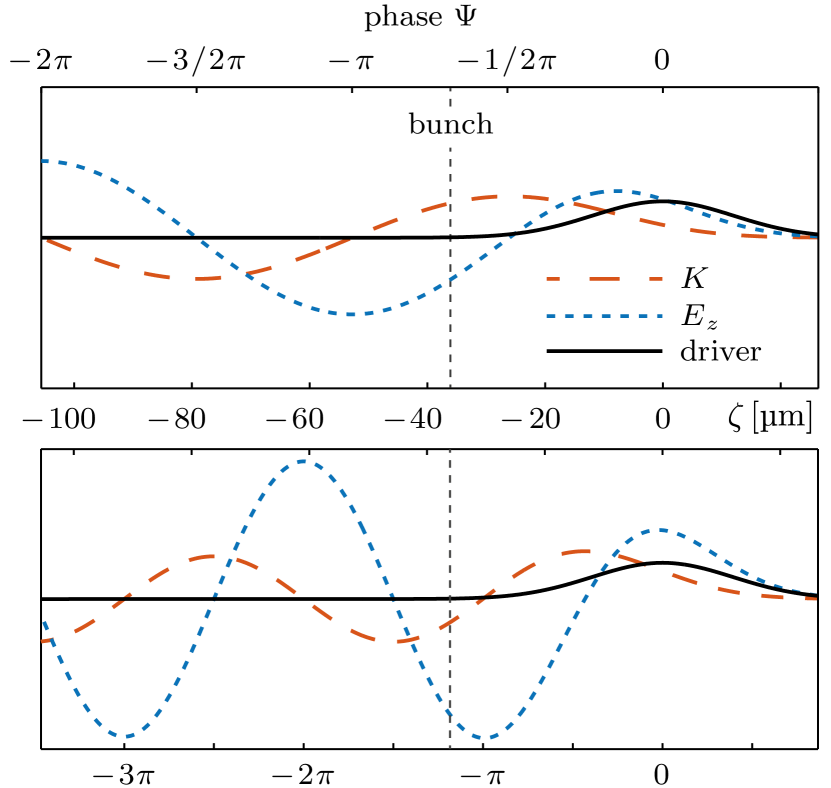
As a novel approach to this problem, we illustrate our concept of chirp mitigation via alternating focusing in figure 1. The top panel shows the fields in the plasma cavity, eqs. (1) and (2), for a density , where the bunch is at an accelerating and focusing phase. For a fixed delay , but higher density , the bunch is defocused, but accelerated by a field of opposite slope and higher amplitude. Shifting the bunch between both phases with a periodically modulated plasma density then allows to mitigate chirp evolution.
Successful implementation of the concept requires stable beam transport through the periodically focusing and defocusing regions of the plasma. We now derive a condition for stable beam transport. In general, an electron under the influence of a constant focusing force is propagated along by the transport matrix ,
Here, and . To describe the transport over one period of the modulated plasma density, we approximate the focusing profile by a sequence of stepwise constant . The transport matrix over is then . Stable transport requires Courant and Snyder (1958). To describe the evolution of the whole electron beam, we use the Courant-Snyder parameters , and , with the transverse emittance. They are related to the transport matrix
with being the identity matrix, the phase advance, , and . From this, we can derive the beta function at the beginning of the periodic structure, in our case the beginning of the modulated plasma, that is needed for stable transport
| (3) |
Since depends on , the distance between bunch and driver, also the transport matrix and consequently depend on . Real values of correspond to stable beam transport. The net accelerating field at is . We choose the position of the electron bunch behind the driver such, that (i) we obtain stable transport, eq. (3), and (ii) the bunch is accelerated on-crest of the averaged accelerating field. There, at the minimum of , we maximize the energy gain and mitigate the chirp evolution.
To demonstrate the alternating focusing scheme, we assume in the following a driver laser pulse of Gaussian shape, with , m, and a spot size of m. We further assume a plasma density modulated between and , and a modulation profile,
with and modulation period mm. The parameter describes the steepness and width of the density modulation, with in our example. Note that the high density region is shorter than the low density region: The varying plasma density not only changes the phase of the bunch within the wakefield, but also sign and steepness of the accelerating field gradient. Therefore, the compensation of the chirp requires a larger fraction of than its buildup.
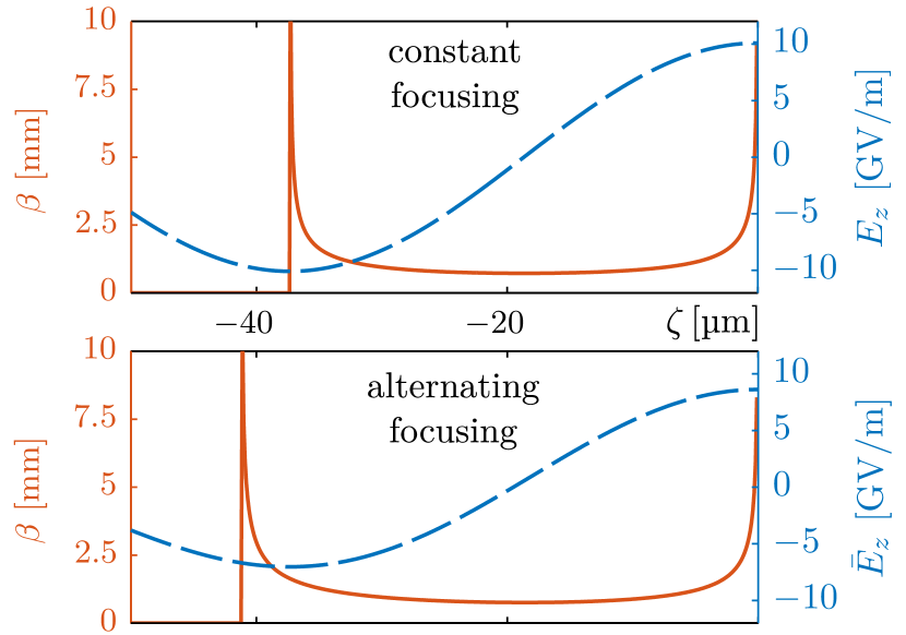
Using this density profile, we calculate and , shown in figure 2 (bottom), and compare it with a reference case of constant density (top). Both cases have a singularity in the beta function, which marks the transition from regions of unstable to stable transport. In the reference case (top), all delays with stable beta function have a gradient in the accelerating field and would thus imprint a chirp on the accelerated bunch. Contrarily, in the alternating focusing case (bottom), we find a delay with a minimum in and a stable beta function. This delay is equivalent to on-crest acceleration in a conventional accelerator, and no chirp is imprinted on the bunch.
To validate our results, we perform 3D particle-in-cell (PIC) simulations using the code Warp Friedman et al. (2014) in the Lorentz boosted frame. The simulation box volume is with cells and one particle per cell. The simulation is boosted by . We inject an external electron beam of 100 MeV, with a bunch length of m, and a normalized emittance of mm.mrad. The transverse size of m is matched to the alternating focusing structure, using the simulated focusing forces and eq. (3). The bunch has a relative energy spread of , no longitudinal chirp, and a bunch charge of pC to avoid beam loading effects. The distance between driver laser and witness bunch is chosen slightly larger than the analytical estimation with to account for the relativistically elongated plasma wavelength and slippage effects. For reference, we perform a simulation with the same parameters but with a constant flat-top plasma profile of density , and here .
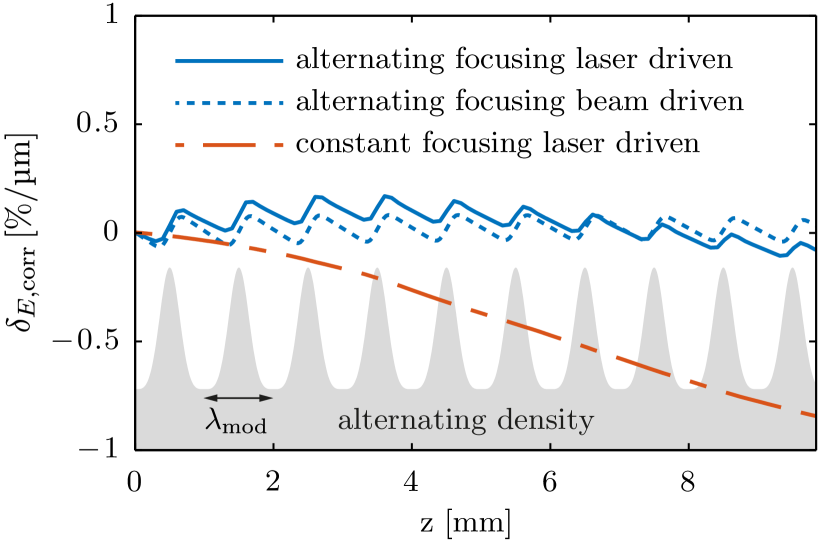
Figure 3 shows the evolution of the correlated energy spread (chirp) for both cases. In the reference case (red dashed) the bunch is in the focusing region, thus off-crest of the accelerating field, and develops a steadily increasing energy chirp. In contrast, using a modulated plasma density, the energy chirp is compensated after every modulation period . As the electron bunch is faster than the laser in the plasma, it slowly slips through the minimum in , compare figure 2 (bottom), which causes the small global variation of the chirp. This effect could, however, be compensated with a globally tapered plasma density Rittershofer et al. (2010). Over one the chirp builds up faster than it decreases, which is a consequence of the aforementioned asymmetry in plasma density and accelerating field gradient. The beam emittance is conserved throughout the entire plasma.
We further investigate the alternating focusing scheme for an electron beam driven wakefield with 3D simulations using the PIC code HiPACE Mehrling et al. (2014) with a simulation box volume of with cells. For this purpose, we assume a Gaussian driver with m, m, and mm.mrad. The driver peak density of corresponds to a charge of 400 pC. For simplicity, we choose in this conceptual study a driver beam energy of , to prevent an evolution of the driver, with an energy spread of .
The witness bunch of 0.01 pC has a Gaussian shape with m, , and . Its initial energy is with an initially uncorrelated energy spread of .
We use the same modulated plasma profile as before and select the driver beam density such that the ratio is the same as in the laser driven case, which makes both comparable. Analog to the laser driven case, we calculate and , and choose such that the witness is in the minimum of .
As expected, our simulations show, that the energy chirp of the accelerated bunch is compensated, as in the laser-driven case, see figure 3. Since there is no slippage between witness and driver, we find no modulation in the global chirp evolution, and conclude that our scheme works for both laser and beam driven scenarios.
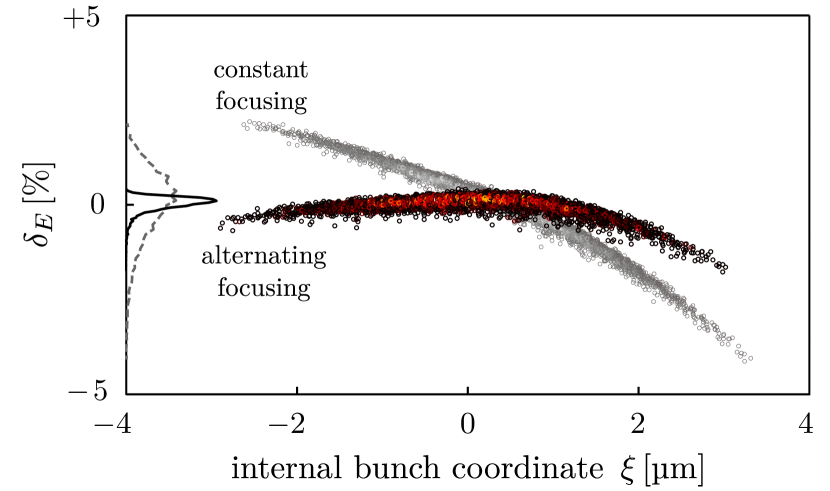
In figure 4, we compare the witness beam phase space of the laser-driven AF case to the reference case at the end of the plasma. Using the alternating focusing scheme, the bunch has virtually no correlated energy spread, unlike the reference case (grey). The projected rms energy spread is reduced by a factor of 4 to , compared to in the reference case.
As presented here, our concept is based on the linear wakefield regime. The approach, however, is general, and could also be applied to different plasma densities, driver properties, and to the non-linear regime. For the latter, further studies are necessary to determine limitations arising from the shortening of the defocusing region and the changed focusing forces.
In conclusion, we have proposed a novel alternating focusing scheme for laser- and beam-driven wakefield accelerators, based on a modulated plasma density profile. Our concept effectively suppresses the buildup of large energy chirps during acceleration, while conserving beam emittance, which is crucial for any staged acceleration scheme. Thus, it promises to overcome one of the major challenges in the field, the generation of electron beams of a quality that rivals and possibly outperforms those from traditional radio-frequency accelerators. By providing the freedom to shape the net accelerating field along the bunch, alternating focusing may be the key concept to unleash the potential of plasma-based accelerator technology for applications.
We gratefully acknowledge the computing time provided on the supercomputer JURECA under project HHH20. We acknowledge the use of the High-Performance Cluster (IT-HPC) at DESY. This work was funded in part by the Humboldt Professorship of B. Foster, the DAAD, and the Helmholtz Virtual Institute VH-VI-503.
References
- Veksler (1957) V. I. Veksler, The Soviet Journal of Atomic Energy 2, 525 (1957).
- Esarey et al. (2009) E. Esarey, C. B. Schroeder, and W. P. Leemans, Rev. Mod. Physs 81, 1229 (2009).
- Rechatin et al. (2009) C. Rechatin, J. Faure, A. Ben-Ismail, J. Lim, R. Fitour, A. Specka, H. Videau, A. Tafzi, F. Burgy, and V. Malka, Phys. Rev. Lett. 102, 164801 (2009).
- Maier et al. (2012) A. R. Maier, A. Meseck, S. Reiche, C. B. Schroeder, T. Seggebrock, and F. Grüner, Phys. Rev. X 2, 031019 (2012).
- Huang et al. (2012) Z. Huang, Y. Ding, and C. B. Schroeder, Phys. Rev. Lett. 109, 204801 (2012).
- Schroeder et al. (2010) C. Schroeder, E. Esarey, C. Geddes, C. Benedetti, and W. Leemans, Phys. Rev. ST Accel. Beams 13 (2010), 10.1103/PhysRevSTAB.13.101301.
- Assmann and Yokoya (1998) R. Assmann and K. Yokoya, Nucl. Instr. Meth. A 410, 544 (1998).
- Mehrling et al. (2012) T. Mehrling, J. Grebenyuk, F. S. Tsung, K. Floettmann, and J. Osterhoff, Phys. Rev. ST Accel. Beams 15, 111303 (2012).
- Dornmair et al. (2015) I. Dornmair, K. Floettmann, and A. R. Maier, Phys. Rev. ST Accel. Beams 18, 041302 (2015).
- Courant et al. (1952) E. D. Courant, M. S. Livingston, and H. S. Snyder, Phys. Rev. 88, 1190 (1952).
- Gorbunov and Kirsanov (1987) L. M. Gorbunov and V. I. Kirsanov, Sov. Phys. JETP 66, 290 (1987).
- Katsouleas et al. (1987) T. C. Katsouleas, S. Wilks, P. Chen, J. M. Dawson, and J. J. Su, Part. Accel. 22, 81 (1987).
- Courant and Snyder (1958) E. D. Courant and H. S. Snyder, Annals of Physics 3, 1 (1958).
- Friedman et al. (2014) A. Friedman, R. H. Cohen, D. P. Grote, S. M. Lund, W. M. Sharp, J.-L. Vay, I. Haber, and R. A. Kishek, IEEE Trans. Plasma Sci. 42, 1321 (2014).
- Rittershofer et al. (2010) W. Rittershofer, C. B. Schroeder, E. Esarey, F. J. Grüner, and W. P. Leemans, Physics of Plasmas 17, 063104 (2010).
- Mehrling et al. (2014) T. Mehrling, C. Benedetti, C. B. Schroeder, and J. Osterhoff, Plas. Phys. Controlled Fusion 56, 084012 (2014).