Tunable magnetic alignment between trapped exciton-polariton condensates
Abstract
Tunable spin correlations are found to arise between two neighboring trapped exciton-polariton condensates which spin-polarize spontaneously. We observe a crossover from an antiferromagnetic- to a ferromagnetic pair state by reducing the coupling barrier in real-time using control of the imprinted pattern of pump light. Fast optical switching of both condensates is then achieved by resonantly but weakly triggering only a single condensate. These effects can be explained as the competition between spin bifurcations and spin-preserving Josephson coupling between the two condensates, and open the way to polariton Bose-Hubbard ladders.
The development of spin-charge lattice models for understanding strongly-correlated states of matter is a successful theme of modern quantum physics. This has driven the desire to model and probe complex condensed matter phenomena using highly-controlled systems, such as ultracold atoms Bloch et al. (2008), photons Szameit and Nolte (2010); Hafezi et al. (2013), or superconducting junctions You and Nori (2011). Exciton-polariton (polariton) lattices have emerged as an alternative system Carusotto and Ciuti (2013); Jacqmin et al. (2014) with unique properties. Due to their strongly dissipative and nonlinear nature, many-body polariton gases can reach steady states which are remarkably different from their equilibrium case Le Boité et al. (2013). Moreover, they have peculiar spin properties Leyder et al. (2007); Lagoudakis et al. (2009); Sala et al. (2015) and exhibit spontaneous magnetization (emitting circularly polarized light) above a critical bifurcation threshold Ohadi et al. (2015), analogous to the weak lasing regime Aleiner et al. (2012). In this Letter we study the basic building block of a polariton spin lattice: two optically trapped spin-polarized condensates which are tunably coupled. We demonstrate that trapped out-of-equilibrium polariton condensates can exhibit Ising-like behavior related to spin bifurcations. The two condensate system investigated here is shown to correspond to one plaquette of a bosonic ladder Atala et al. (2014), and allows demonstration of a crossover in the competition between Josephson coupling and spin bifurcation. These features have not been seen in any other system to date.
Polariton condensates are coherent many-body states Deng et al. (2002); Kasprzak et al. (2006); Balili et al. (2007); Baumberg et al. (2008), which can be confined in potentials Wertz et al. (2010); Tosi et al. (2012a); Cristofolini et al. (2013) and interact with each other via Josephson junctions Lai et al. (2007); Lagoudakis et al. (2010); Tosi et al. (2012b); Abbarchi et al. (2013). For a pair of interacting trapped spin-polarized condensates, their polarization states are expected to couple. However, the driven-dissipative and nonlinear nature of polariton condensates makes the underlying coupling mechanism considerably richer than that in the conventional Ising case, leading to exotic forms of magnetism where the orientation and strength of coupling is not determined by the sign of the interaction.
We achieve tuning between ferromagnetic (F) or antiferromagnetic (AF) coupling by directly modulating the tunneling barrier, adjusting either the height of the barrier or the separation between the condensates. We show how optical switching of the spin state of one condensate results in fast switching of the state of the neighboring condensate. Our result is a key step towards using trapped polariton condensates for the realization of interacting bosons in a driven-dissipative spinor Bose-Hubbard model Le Boité et al. (2013); Carusotto and Ciuti (2013).
The Bose-Hubbard model with polaritons can be studied in other systems where, for example, the sample is etched to form micro-pillar arrays Abbarchi et al. (2013); Jacqmin et al. (2014); Sala et al. (2015), metal films are deposited on the surface of the cavity Lai et al. (2007); Kim et al. (2008, 2011), or surface acoustic waves are applied Cerda-Méndez et al. (2010). While the confinement potential is then separate from the condensate gain, the trapped exciton-polaritons studied in the present letter have the advantage that the confinement, even at a single site level, is versatile and can be adjusted on the fly. Particularly for larger arrays of condensates, this capability to tune the different barriers is vital. Moreover, the interaction with the reservoir particles is reduced, crucial for spin stability.
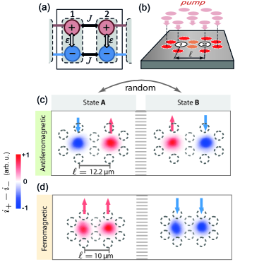
Exciton-polaritons (polaritons) are quasiparticles formed by the strong coupling of excitons in semiconductor quantum wells with photons in the microcavity in which they are embedded Kavokin et al. (2007). We create optically trapped polariton condensates Cristofolini et al. (2013); Askitopoulos et al. (2013); Dreismann et al. (2014) by nonresonant linearly-polarized continuous wave (CW) excitation of a membrane microcavity (for details see SI. 1). Driven by their repulsive excitonic interactions, polaritons travel away from the pump region and feed the zero-momentum ground state at the center of the optical trap. Once the density exceeds the condensation threshold, a macroscopically coherent condensate forms in the trap center. Polaritons in quantum-well microcavities have two (spin up or down) projections of their total angular momentum along the structure growth axis, which correspond to right- and left-circularly polarized photons emitted by the cavity (of intensities ).
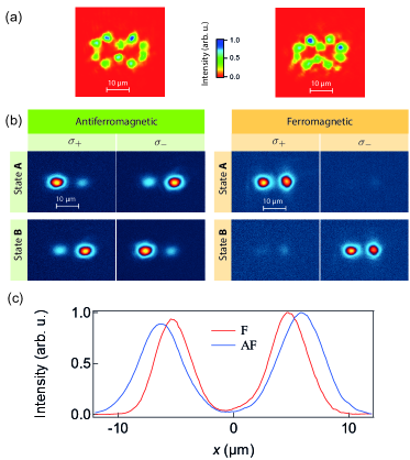
Trapped polariton condensates spontaneously exhibit a high degree of circular polarization, or magnetization , above a critical spin-bifurcation threshold as a result of energy and dissipation splitting of their linear polarizations Ohadi et al. (2015). We operate above this spin-bifurcation threshold, which means that the trapped condensate is spin-polarized in either spin-up or spin-down states. These spin-polarized condensates emit nearly circularly polarized (85%) light, which can be measured using conventional polarimetry. In each realization we excite the sample for and measure the condensate , where denotes the left and right condensate (see SI. 2). The optical excitation is patterned using a spatial light modulator (SLM) into the shape of a double-hexagon as shown by dashed circles in Fig. 1(b-d) such that a spin-polarized condensate is formed at the center of each hexagon. The middle ‘barrier’ pump spots [orange in Fig. 1(b)] between the two traps are weaker than the outer spots (intensity ratio ) to allow inter-trap tunneling of polaritons.
We can spatially squeeze or stretch the traps and change the condensates separation without changing the barrier pump intensity. To achieve this the barrier pump spots of the double-hexagon trap are fixed while shifting the location of the other spots. When the separation of the condensates maxima is greater than , the two condensates independently pick a spin-up or spin-down state. However, when this is decreased to , we observe AF coupling, where the condensates spontaneously collapse into either or states in each realization [Fig. 1(c), see also SI. 2]. Further decreasing the separation to , we observe F coupling where the condensates pick either of or states randomly in each realization [Fig. 1(d)]. As in the case of a single condensate Ohadi et al. (2015), these states remain stable for many seconds at , and do not depend on the position on the sample, the geometrical pattern of the pump spots or the power above the spin-bifurcation threshold.
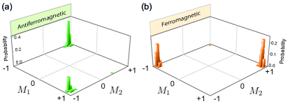
For each set of trapping conditions, realizations are created and for each we measure for the two condensates to perform a statistical analysis of the condensate-pair spin correlation. Each polarization-resolved realization is recorded for by a camera, allowing us to map the 2D histogram of and resolving F and AF situations (Fig. 2). Absolute correlations of are found for the condensate spins in both coupling regimes. Increasing the condensate separation to reduces this correlation to 0.09, confirming that condensate spins then become uncoupled. It is important to note that we observe partial phase coherence between the condensates in both AF and F regimes, and the condensates are at equal energies (see SI. 3).
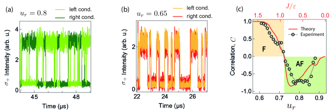
To accurately map the magnetic phase diagram of the system the influence of barrier on condensate spin correlation is investigated. Instead of changing the separation of the condensates by changing the trap geometry, we vary their barrier potential. For this the intensity of the barrier pump spots [orange, Fig. 1(a)] is changed. This allows finer control over the coupling interaction than changing the separation of the condensates, which is discretized due to single-pixel shifting of the SLM. To better observe the correlations, we induce spin flips by increasing the spin noise via spatially broadening the pump spots, which increases the overlap of the condensates and the pump. This increases the spontaneous spin-flip rate of the condensates (here set to 10 flips/, see also SI. 4), allowing faster and more reliable correlation measurements within the stability time of our setup. Since the energy blueshift from pump-injected excitons is proportional to the pump intensity Askitopoulos et al. (2013), the ratio of the intensity of barrier pump spots to the other spots, , is a reliable measure of the relative barrier height. The blueshift above the condensate energy at the saddle point of the barrier is , where (see also SI. 3). Selecting the right-circularly polarized () emission, we spatially resolve the left and right condensates recording their intensities at each for using photomultipliers. A typical trace for [Fig. 3(a)] shows that the double condensates flip randomly between the two AF states with a switching time limited by our measurement resolution (). Reducing to 0.65 shows now flipping between two F-states [Fig. 3(b)]. For each barrier potential we record 20 traces (each lasting ) and calculate the average correlation of the condensates spins, plotting this as a function of [Fig. 3(c)]. We observe a clear transition from the ferromagnetic to antiferromagnetic state at . Increasing further results in zero coupling.
The uncoupling of the condensates when increasing their separation (while the intensity of the shared pump spots remains constant) implies that the shared reservoir between two condensates does not play a significant role here. Our trapped condensates form with =0 (), where the transverse-electric and transverse-magnetic splitting vanishes Shelykh et al. (2004). As a result the optical spin-Hall effect Kavokin et al. (2005) is negligible in trapped condensates, with spin torque rates much smaller than tunnelling rates thus preserving spin during the Josephson process 111At the half-wavelength of the spin precession observed in Ref. 44 is , which is more than 2 orders of magnitude larger than the condensate separations we have here.. On the other hand, observation of phase coherence between the condensates signifies that the spin coupling must be mediated by a coherent mechanism, as described by our theory below.
Our description of above effects is based on the theory for a single trapped condensate Ohadi et al. (2015), which is extended to include the Josephson coupling Wouters and Carusotto (2007); Shelykh et al. (2008); Read et al. (2010) between the two condensates. The order parameter for each exciton-polariton condensate is a two-component complex vector and and are the spin-up and spin-down wave functions. The components of the order parameter define the measurable condensate pseudospin , and the normalized spin vector , where are the Pauli matrices. The order parameters evolve according to the driven dissipative equation
| (1) | ||||
Here is the pumping-dissipation balance, is the (average) dissipation rate, is the incoherent in-scattering (or ‘harvest’ rate), and captures the gain-saturation term Keeling and Berloff (2008). This gain saturation depends on the total occupation of the condensate (treated more generally in Ref. Ohadi et al. (2015)). (horizontal) and (vertical) linearly-polarized single-polariton states are split in energy by and dissipation rate by . The repulsive interaction constant for polaritons with the same spin is , and the interaction constant for polaritons with opposite spins is . Finally, is the extrinsic spin-preserving Josephson coupling between the left and the right condensate, which we have introduced here to account for coherent coupling.
It is important to note the fundamental differences between the spin coupling mechanism demonstrated here and that seen in closed systems such as atoms trapped in optical lattices Struck et al. (2011); Greif et al. (2013). In equilibrium spin systems such as those described by the Ising model, the coupling is achieved via the minimization of the total energy. In the driven-dissipative system described here, the minimization of energy does not play a direct role since the system is out of equilibrium. Here the spin alignment is a direct result of spin bifurcation correlation, which itself is a product of pumping, dissipation and nonlinearity, and coherent exchange of particles between the two condensates.
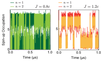
We perform dynamical simulations to calculate spin correlations. We calculate the steady state of the coupled Eq. 1 for realizations with random initial conditions 222Similar to Ref. 11, the parameters used for 0D simulations are: ; ; ; ; ; ; and plot the final circular polarization correlation of the two condensates at different Josephson coupling rates [Fig. 3(c), red line]. For small Josephson amplitudes there is AF coupling of the condensate states. The stable AF configuration is characterized by and , so that Eq. (1) is reduced to the two-component problem with renormalized splitting between - and -polarized states . Correspondingly, the AF state loses stability at when changes sign. The AF state is first converted to the limit cycle motion by the Hopf bifurcation and then to pseudo-chaotic behavior with further increase of . Simultaneously, the stable F configuration with and emerges for . This behavior is in good agreement with the experiment: we observe the AF coupling at high barrier heights where the tunneling rate between two condensates (Josephson coupling) is small and same-site coupling between spins dominates [Fig. 1(a), white arrows]. On the other hand when the barrier height is low, F-coupling is seen since the Josephson coupling dominates [Fig. 1(a), black arrows] 333We note that apart from most probable pure F and AF configuration, other attractors exist for the system (1) even away from the crossover region . In particular, the F configuration for can be also achieved with the broken symmetry.. Each interacting pair of condensates then forms a plaquette, and longer chains of condensates will form a bosonic ladder Atala et al. (2014), which will in future be useful to probe with magnetic fields van der Zant et al. (1992). We note that paired condensates emit light at the same frequency, as it is also found experimentally.
The chaotic dynamics in the AF-F crossover region of the present system is different from the chaos in resonantly excited pair of exciton-polariton condensates studied before Solnyshkov et al. (2009). The trapped exciton-polariton condensates here are excited incoherently, yielding chaos in an autonomous dynamical system. The details of this chaos and its effects on the emission from the trapped condensates will be studied elsewhere.
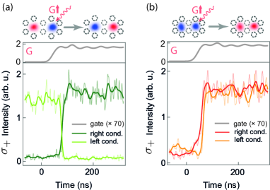
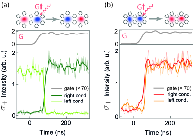
Finally, we demonstrate the resonant switching of the coupled spin states experimentally. We resonantly excite one of the condensates with a narrow linewidth CW diode laser, which we refer to as the gate (G). The membrane microcavity allows resonant excitation from the back side of the cavity without requiring filtering of the laser backscatter. The gate laser as well as the pump can be switched on or off by acousto-optic modulators (AOM) with a rise time of . We resonantly excite the right condensate after we turn on the pump laser. The gate is applied on the right-hand condensate and is right-circularly polarized (). Applying a cross-polarized gate switches the polarization state of the condensate, as previously shown Ohadi et al. (2015). Here, we observe that resonant switching of the spin of one condensate also switches the spin of the other coupled condensate, both in the antiferromagnetic and ferromagnetic regimes (Fig. 4). The condensates remain in the switched state after the gate laser is switched off, due to the bistable nature of the spin states. We note that the resolution-limited condensate switching time reported here is an order of magnitude shorter than that of the gate, clearly showing that (as for single condensates Ohadi et al. (2015)) the switching process is nonadiabatic. Here we are able to switch the coupled spin states by transiently injecting minority spins which are only 1% of the condensates majority spin. Our theoretical description reproduces the fast spin flips observed in the experiment when noise is injected into Eq. 1. Our theory also shows that in both AF- and F-regimes, switching the spin state of condensate 1 also switches the spin of condensate 2, both remaining switched after the pulse is turned off (see SI. 5).
In conclusion, we demonstrate a tunable spin coupling mechanism for trapped polariton condensates. A transition from antiferromagnetic to ferromagnetic coupling is seen as the potential barrier between the condensates decreases. Our results correspond well to the interplay between spin-bifurcation and Josephson coupling in theory. Finally resonant switching of the spin states in both ferromagnetic and antiferromagnetic regimes is shown.
Acknowledgments—Authors acknowledge Andrew Ramsay, Dieter Jaksch and Tomi Johnson for fruitful discussions. This work was supported by EPSRC Grant No. EP/G060649/1, EP/L027151/1, EU Grant No. INDEX 289968, ERC Grant No. LINASS 320503, the Leverhulme Trust Grant No. VP1-2013-011, Spanish MEC (Grant No. MAT2008-01555), the Greek GSRT ARISTEIA Apollo program and Fundación La Caixa, and Mexican CONACYT Grant No. 251808. FP acknowledges financial support through a Schrödinger Fellowship at the University of Oxford and NQIT project (EP/M013243/1). The data corresponding to the figures in this paper can be found at https://www.repository.cam.ac.uk/handle/1810/253679.
References
- Bloch et al. (2008) I. Bloch, J. Dalibard, and W. Zwerger, Rev. Mod. Phys. 80, 885 (2008).
- Szameit and Nolte (2010) A. Szameit and S. Nolte, J. Phys. B: At. Mol. Opt. Phys. 43, 163001 (2010).
- Hafezi et al. (2013) M. Hafezi, S. Mittal, J. Fan, A. Migdall, and J. M. Taylor, Nat. Photon. 7, 1001 (2013).
- You and Nori (2011) J. Q. You and F. Nori, Nature 474, 589 (2011).
- Carusotto and Ciuti (2013) I. Carusotto and C. Ciuti, Rev. Mod. Phys. 85, 299 (2013).
- Jacqmin et al. (2014) T. Jacqmin, I. Carusotto, I. Sagnes, M. Abbarchi, D. D. Solnyshkov, G. Malpuech, E. Galopin, A. Lemaître, J. Bloch, and A. Amo, Phys. Rev. Lett. 112, 116402 (2014).
- Le Boité et al. (2013) A. Le Boité, G. Orso, and C. Ciuti, Phys. Rev. Lett. 110, 233601 (2013).
- Leyder et al. (2007) C. Leyder, M. Romanelli, J. P. Karr, E. Giacobino, T. C. H. Liew, M. M. Glazov, A. V. Kavokin, G. Malpuech, and A. Bramati, Nat. Phys. 3, 628 (2007).
- Lagoudakis et al. (2009) K. G. Lagoudakis, T. Ostatnický, A. V. Kavokin, Y. G. Rubo, R. André, and B. Deveaud-Plédran, Science 326, 974 (2009).
- Sala et al. (2015) V. G. Sala, D. D. Solnyshkov, I. Carusotto, T. Jacqmin, A. Lemaître, H. Terças, A. Nalitov, M. Abbarchi, E. Galopin, I. Sagnes, et al., Phys. Rev. X 5, 011034 (2015).
- Ohadi et al. (2015) H. Ohadi, A. Dreismann, Y. G. Rubo, F. Pinsker, Y. del Valle-Inclan Redondo, S. I. Tsintzos, Z. Hatzopoulos, P. G. Savvidis, and J. J. Baumberg, Phys. Rev. X 5, 031002 (2015).
- Aleiner et al. (2012) I. L. Aleiner, B. L. Altshuler, and Y. G. Rubo, Phys. Rev. B 85, 121301 (2012).
- Atala et al. (2014) M. Atala, M. Aidelsburger, M. Lohse, J. T. Barreiro, B. Paredes, and I. Bloch, Nat Phys 10, 588 (2014).
- Deng et al. (2002) H. Deng, G. Weihs, C. Santori, J. Bloch, and Y. Yamamoto, Science 298, 199 (2002).
- Kasprzak et al. (2006) J. Kasprzak, M. Richard, S. Kundermann, A. Baas, P. Jeambrun, J. M. J. Keeling, F. M. Marchetti, M. H. Szymańska, R. André, J. L. Staehli, et al., Nature 443, 409 (2006).
- Balili et al. (2007) R. Balili, V. Hartwell, D. Snoke, L. Pfeiffer, and K. West, Science 316, 1007 (2007).
- Baumberg et al. (2008) J. Baumberg, A. Kavokin, S. Christopoulos, A. Grundy, R. Butté, G. Christmann, D. Solnyshkov, G. Malpuech, G. Baldassarri Höger von Högersthal, E. Feltin, et al., Phys. Rev. Lett. 101, 136409 (2008).
- Wertz et al. (2010) E. Wertz, L. Ferrier, D. D. Solnyshkov, R. Johne, D. Sanvitto, A. Lemaître, I. Sagnes, R. Grousson, A. V. Kavokin, P. Senellart, G. Malpuech, and J. Bloch, Nat. Phys. 6, 860 (2010).
- Tosi et al. (2012a) G. Tosi, G. Christmann, N. G. Berloff, P. Tsotsis, T. Gao, Z. Hatzopoulos, P. G. Savvidis, and J. J. Baumberg, Nat. Phys. 8, 190 (2012a).
- Cristofolini et al. (2013) P. Cristofolini, A. Dreismann, G. Christmann, G. Franchetti, N. G. Berloff, P. Tsotsis, Z. Hatzopoulos, P. G. Savvidis, and J. J. Baumberg, Phys. Rev. Lett. 110, 186403 (2013).
- Lai et al. (2007) C. W. Lai, N. Y. Kim, S. Utsunomiya, G. Roumpos, H. Deng, M. D. Fraser, T. Byrnes, P. Recher, N. Kumada, T. Fujisawa, and Y. Yamamoto, Nature 450, 529 (2007).
- Lagoudakis et al. (2010) K. G. Lagoudakis, B. Pietka, M. Wouters, R. André, and B. Deveaud-Plédran, Phys. Rev. Lett. 105, 120403 (2010).
- Tosi et al. (2012b) G. Tosi, G. Christmann, N. G. Berloff, P. Tsotsis, T. Gao, Z. Hatzopoulos, P. G. Savvidis, and J. J. Baumberg, Nat. Comm. 3, 1243 (2012b).
- Abbarchi et al. (2013) M. Abbarchi, A. Amo, V. G. Sala, D. D. Solnyshkov, H. Flayac, L. Ferrier, I. Sagnes, E. Galopin, A. Lemaître, G. Malpuech, and J. Bloch, Nat. Phys. 9, 275 (2013).
- Kim et al. (2008) N. Y. Kim, C.-W. Lai, S. Utsunomiya, G. Roumpos, M. Fraser, H. Deng, T. Byrnes, P. Recher, N. Kumada, T. Fujisawa, and Y. Yamamoto, phys. stat. sol. (b) 245, 1076 (2008).
- Kim et al. (2011) N. Y. Kim, K. Kusudo, C. Wu, N. Masumoto, A. Löffler, S. Höfling, N. Kumada, L. Worschech, A. Forchel, and Y. Yamamoto, Nat. Phys. 7, 681 (2011).
- Cerda-Méndez et al. (2010) E. A. Cerda-Méndez, D. N. Krizhanovskii, M. Wouters, R. Bradley, K. Biermann, K. Guda, R. Hey, P. V. Santos, D. Sarkar, and M. S. Skolnick, Phys. Rev. Lett. 105, 116402 (2010).
- Kavokin et al. (2007) A. V. Kavokin, J. Baumberg, G. Malpuech, and F. P. Laussy, Microcavities (Oxford Univ. Press, Oxford, 2007).
- Askitopoulos et al. (2013) A. Askitopoulos, H. Ohadi, A. V. Kavokin, Z. Hatzopoulos, P. G. Savvidis, and P. G. Lagoudakis, Phys. Rev. B 88, 041308 (2013).
- Dreismann et al. (2014) A. Dreismann, P. Cristofolini, R. Balili, G. Christmann, F. Pinsker, N. G. Berloff, Z. Hatzopoulos, P. G. Savvidis, and J. J. Baumberg, Proc. Natl. Acad. Sci. U.S.A. 111, 8770 (2014).
- Shelykh et al. (2004) I. Shelykh, K. V. Kavokin, A. V. Kavokin, G. Malpuech, P. Bigenwald, H. Deng, G. Weihs, and Y. Yamamoto, Phys. Rev. B 70, 035320 (2004).
- Kavokin et al. (2005) A. Kavokin, G. Malpuech, and M. Glazov, Phys. Rev. Lett. 95, 136601 (2005).
- Note (1) At the half-wavelength of the spin precession observed in Ref. 44 is , which is more than 2 orders of magnitude larger than the condensate separations we have here.
- Wouters and Carusotto (2007) M. Wouters and I. Carusotto, Phys. Rev. Lett. 99, 140402 (2007).
- Shelykh et al. (2008) I. A. Shelykh, D. D. Solnyshkov, G. Pavlovic, and G. Malpuech, Phys. Rev. B 78, 041302 (2008).
- Read et al. (2010) D. Read, Y. G. Rubo, and A. V. Kavokin, Phys. Rev. B 81, 235315 (2010).
- Keeling and Berloff (2008) J. Keeling and N. G. Berloff, Phys. Rev. Lett. 100, 250401 (2008).
- Struck et al. (2011) J. Struck, C. Ölschläger, R. L. Targat, P. Soltan-Panahi, A. Eckardt, M. Lewenstein, P. Windpassinger, and K. Sengstock, Science 333, 996 (2011).
- Greif et al. (2013) D. Greif, T. Uehlinger, G. Jotzu, L. Tarruell, and T. Esslinger, Science 340, 1307 (2013).
- Note (2) Similar to Ref. 11, the parameters used for 0D simulations are: ; ; ; ; ; ; .
- Note (3) We note that apart from most probable pure F and AF configuration, other attractors exist for the system (1\@@italiccorr) even away from the crossover region . In particular, the F configuration for can be also achieved with the broken symmetry.
- van der Zant et al. (1992) H. S. J. van der Zant, F. C. Fritschy, W. J. Elion, L. J. Geerligs, and J. E. Mooij, Phys. Rev. Lett. 69, 2971 (1992).
- Solnyshkov et al. (2009) D. D. Solnyshkov, R. Johne, I. A. Shelykh, and G. Malpuech, Phys. Rev. B 80, 235303 (2009).
- Kammann et al. (2012) E. Kammann, T. C. H. Liew, H. Ohadi, P. Cilibrizzi, P. Tsotsis, Z. Hatzopoulos, P. G. Savvidis, A. V. Kavokin, and P. G. Lagoudakis, Phys. Rev. Lett. 109, 036404 (2012).
Supplemental Information
1 Experimental methods
The cavity’s top (bottom) distributed Bragg reflector (DBR) is made of 32 (35) pairs of Al0.15Ga0.85As/AlAs layers of /. Four sets of three GaAs quantum wells (QW) separated by thick layers of Al0.3Ga0.7As are placed at the maxima of the cavity light field. The 5/2 () cavity is made of Al0.3Ga0.7As. The microcavity sample is chemically etched from the substrate side to form diameter membranes allowing optical access from the back of the sample for resonant excitation. Note the phenomena reported in this paper do not depend on this etching, which is merely to conveniently explore the resonant gating regime. The sample shows condensation under nonresonant excitation tsotsis_lasing . The CW pump is a single-mode Ti:Sapphire laser tuned to the first Bragg mode above the condensate energy, and is linearly polarized. In order to create short time-scale realizations, the pump is amplitude-modulated by an AOM (rise time ). A SLM is used to spatially pattern the pump beam into a double hexagon using the MRAF algorithm MRAF . The separation of the pump spots can only be changed within the single-pixel shift limit of the SLM; however, the intensity of the individual spots can be changed nearly arbitrarily. A 0.4 NA objective is used for imaging the pattern onto the sample. The pulsed gate, which is applied on the back side of the membrane, is a circularly-polarized CW single-mode extended cavity diode laser, which is amplitude modulated using a second AOM. A cooled CCD and a spectrometer is used for imaging and energy resolving the photoluminescence (PL). PL is analyzed using a quarter-waveplate and a Wollaston prism in front of the camera. Two photomultiplier tubes (PMT) and a fast oscilloscope () are used for time-resolving the polarization-resolved PL of the left and right condensates. The CCD, the pump/gate laser and the oscilloscope are all synchronized together using arbitrary function generators ().
2 real-space
We can squeeze or stretch the trap without affecting the barrier pump spots [Fig.S1(a)]. Using a Wollaston prism in front of the CCD, we measure both circular polarization components simultaneously for many realizations, as shown in Fig. S1. Here, each realization is a short-time exposure of the sample (). The degree of circular polarization is given by , where is the intensity image of the right- and left-circularly polarized emission. The emitted polarization is not exactly circular due to the spin bifurcation mechanism which shows the stable states have a small fraction of linear polarization ohadi_spontaneous_2015_SI . The spatial separation of the two condensates is extracted from the line profiles in Fig. S1(c).
3 Phase and Energy
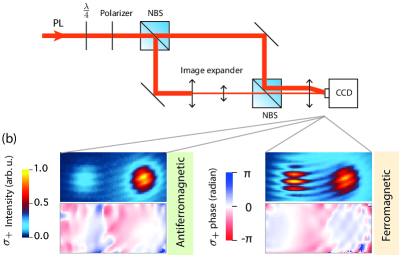
To experimentally study the phase coherence between the two condensates, a modified Michelson interferometer is used, as shown in Fig. S2. The circularly polarized PL is 5 times expanded in one arm and is superimposed onto that from the other arm. By doing this the PL of one condensate overlaps the PL from both condensates. The vertical displacement of the beams from the two arms on a final lens before the CCD results in fringes. Observation of fringes shows that we have partial phase coherence between the two condensates ( 1 order deg of coherence ). The phase can be extracted by selecting the first-order diffraction of the Fourier transformed images and transforming it back into real-space images. We observe near zero phase difference in the circularly polarized basis of both AF and F regimes.
Phase fluctuations in exciton-polariton condensates are shown to be due to a combination of condensate number fluctuations and the interaction of the condensate with the excitonic reservoir love_intrinsic_2008 . Both effects perturb the phases of the two condensates independently because the two condensates have separate reservoirs. On the other hand, the coherent exchange of particles via Josephson coupling between the two condensates tries to lock their phases. The mutual coherence is then set by the interplay between these two effects. The phase coherence is zero in the case where the condensates are completely uncoupled and gradually increases as the Josephson interaction increases.
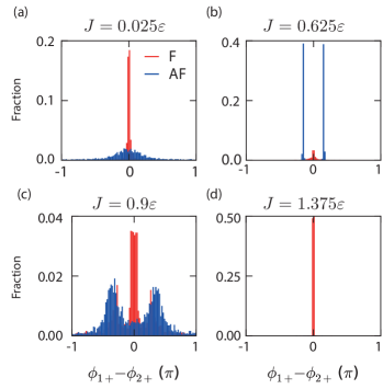
Our dynamical simulation also predicts a nearly zero phase difference between the same spin components in both F and AF regimes. Fig. S3 shows a histogram of the phase difference between same spin components of the left and right condensates () as a function of the Josephson coupling rate . For small Josephson couplings (), F-states with zero phase difference appear, but their fraction rapidly decreases as increases until two stable AF-states with broken phase symmetry appear (). At the transition point () the AF states destabilize and as increases further one stable F-state appears ().
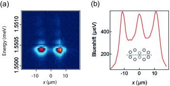
Observation of interference fringes suggest that the two condensates have equal energies. This is confirmed by energy resolving the condensate emission. We observe that the two condensates emit light at the same frequency. In the experiment the energies of the two condensates are close () even when they are uncoupled because experimentally the two traps are symmetric, i.e., the pattern intensity is the same for both traps. Then the coherent coupling between the two traps pulls the emission frequencies together, in a similar fashion to the injection locking of two laser oscillators stover_locking_1966 .
By measuring the blueshift of polaritons across the saddle points of the double-hexagon trap, we can extract the potential profile, as shown in Fig. S4. The potential barrier between the two traps is a linear function of the middle pump spots intensity and is at .
4 Pump-induced spin flips
In previous work ohadi_spontaneous_2015_SI , we demonstrated how the interaction of the condensate with pump-induced reservoir results in the reduction of the average condensate magnetization . In that work we noted:
“In a similar fashion to thermal noise, an overlapping reservoir can also induce spin noise in the condensate. The spin noise causes condensate spin flips, which result in the reduction of the time-averaged circular polarization. Theoretically, this can be studied by introducing a noise term similar to Eq. (9), but instead of depending on temperature, the noise intensity depends on the overlapping reservoir density.”
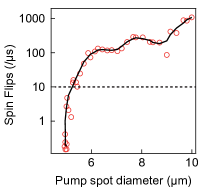
Here, we quantify the influence of the reservoir on the spin-flip rate, as shown in Fig. S5. We measure the rate of condensate spin-flips over as a function of pump spot diameter. We observe that the condensate spin-flip rate increases exponentially as the overlap between the reservoir and condensate increases and plateaus, most probably due to finite resolution of our detection system. To measure the spin correlations as a function of trap barrier, we broaden the pump spots to , marked by a dotted line in Fig. S5.
5 resonant excitation and spin noise
To investigate resonant excitation and spin noise we modify our driven dissipative equation to
| (S1) | ||||
Here, is a two-component function representing resonant excitation at frequency . To demonstrate spin-switching within our theoretical framework, we set the resonant gate excitation to a right-circularly polarized () pulse which is applied to condensate 1 at for a duration of . In both the AF-regime and the F-regime, when the spin state of condensate 1 is switched, condensate 2 also switches spin, as shown in Fig. S6. Moreover, both condensates stay in the switched state after the pulse is turned off.
To demonstrate noise-induced spin flips a spin noise function is added to Eq. S1. Here, where with is a realization of Gaussian random processes with zero mean and -like two-point correlation function:
| (S2) | ||||
| (S3) |
where is the total noise intensity. Fig. S7 shows the influence of spin noise on the coupled condensates. We observe that in both regimes, noise-induced spin flips in one condensate switch the spin of the neighboring condensate, in agreement with the experiment.
References
- (1) P. Tsotsis, P. S. Eldridge, T. Gao, S. I. Tsintzos, Z. Hatzopoulos, and P. G. Savvidis, N. J. Phys 14, 023060 (2012).
- (2) M. Pasienski and B. DeMarco, Opt. Express 16, 2176 (2008).
- (3) H. Ohadi, A. Dreismann, Y. G. Rubo, F. Pinsker, Y. del Valle-Inclan Redondo, S. I. Tsintzos, Z. Hatzopoulos, P. G. Savvidis, and J. J. Baumberg, Phys. Rev. X 5, 031002 (2015).
- (4) A. P. D. Love, D. N. Krizhanovskii, D. M. Whittaker, R. Bouchekioua, D. Sanvitto, S. Al Rizeiqi, R. Bradley, M. S. Skolnick, P. R. Eastham, R. André, and Le Si Dang, Phys. Rev. Lett. 101, 067404 (2008)].
- (5) H. L. Stover and W. H. Steier, Appl. Phys. Lett. 8, 91 (1966)