{jing.liu,john.backes,darren.cofer,andrew.gacek}@rockwellcollins.com
From Design Contracts to Component Requirements Verification
Abstract
During the development and verification of complex airborne systems, a variety of languages and development environments are used for different levels of the system hierarchy. As a result, there may be manual steps to translate requirements between these different environments. This paper presents a tool-supported export technique that translates high-level requirements from the software architecture modeling environment into observers of requirements that can be used for verification in the software component environment. This allows efficient verification that the component designs comply with their high-level requirements. It also provides an automated tool chain supporting formal verification from system requirements down to low-level software requirements that is consistent with certification guidance for avionics systems. The effectiveness of the technique has been evaluated and demonstrated on a medical infusion pump and an aircraft wheel braking system.
Keywords:
design contracts, specification model, design model, AGREE, Simulink, requirements-based verification, certification1 Introduction
As part of the software development process for complex avionics systems, system requirements are iteratively decomposed, allocated, and refined to lower level requirements for software and hardware components. Different verification processes are used to provide evidence that these components satisfy their requirements. The focus of all development and verification activities in the avionics domain is to ensure that a system meets its requirements and contains no unintended functionality.
Requirements at different levels of the system hierarchy may be specified using different languages and development environments. Even when formal methods tools are used to verify requirements, there may be manual steps to translate requirements between these different environments. The work presented in this paper attempts to close the gap between verification at the system level and the component level.
We present a tool-supported technique that translates requirements from a system-level reasoning framework into observers of requirements for software components. The observers that the tool produces can be verified using a model checker specialized to the software component development language. Our work closes the gap between high-level requirements captured with the software architecture and low-level requirements for component implementation. This ensures consistency of the verification results and improves productivity and accuracy through the use of automation to eliminate manual steps. Furthermore, making these property observers available during the design process supports early verification of the software components.
In previous work, we have developed a compositional analysis environment [1, 2] based on the Architecture Analysis and Design Language (AADL) [3]. AADL can be used to model both the hardware and software aspects of the system, but in this work we have limited our attention to the software architecture. In our compositional analysis approach, the AADL model is augmented with assume-guarantee contracts to capture both system-level requirements and the requirements for the software components.
In the present work, we link the component contracts to their implementations in Simulink® [4], a framework developed by MathWorks® and integrated with MATLAB®. Simulink provides a graphical programming environment for modeling, simulation, code generation, testing, and formal analysis. It is widely used in the avionics industry. By automatically translating formal contracts for software component behavior into specifications that can be checked in the Simulink environment, we now support a complete top-to-bottom development process with formal verification of all requirements. Furthermore, the design of our approach is sufficiently general that it can be adapted to support other software development environments and languages.
Since our objective is the production of high-assurance software for avionics, we must be cognizant of how this approach will fit into a certification context. As we will show, our approach has been designed to be consistent with new certification guidance related to the use of formal methods and model-based development processes.
The rest of the paper is organized as follows. Section 2 provides background information related to the development and analysis environment, including certification considerations. Section 3 describes the contract translation process in detail. Section 4 evaluates the techniques in an avionics system case study and a medical device system case study. Section 5 describes related work and Section 6 presents concluding remarks.
2 Preliminaries
In this section, we describe the overall design flow and introduce some terminology associated with the certification context. We also describe the system architecture modeling environment and the software component modeling environment that we are using.
2.1 Design Flow from Architecture to Component
One of our goals is to transition the tools we have developed into use by the system and software engineers who develop avionics products. Therefore, we need to understand how the tools and the models they produce will fit into the certification process.
Certification guidance for software in commercial aircraft is found in DO-178C, Software Considerations in Airborne Systems and Equipment Certification [5]. The process described in DO-178C is essentially a waterfall model in which system requirements are allocated to hardware and software, becoming high-level requirements for each. High-level requirements are refined to become a software design, consisting of software architecture and low-level requirements from which individual software components can be developed.
DO-178C is accompanied by several supplement documents which provide guidance for the use of specific technologies, including formal methods (DO-333 [6]) and model-based development (DO-331 [7]). DO-333 describes how software life-cycle artifacts such as high and low-level requirements can be expressed as formal properties and how formal analysis tools can be used to satisfy many certification objectives. DO-331 provides guidance on how software life-cycle artifacts expressed as different types of models fit into the certification process. A case study showing how different formal methods can be used to satisfy certification objectives is found in [8], including a model-based example that uses Simulink [4] and Simulink Design VerifierTM [9].
DO-331 describes the relationships between models at the system and software levels, and distinguishes between specification models and design models. A specification model represents high-level requirements that provide an abstract representation of functional, performance, interface, or safety characteristics of software components. Specification models do not define software design details or prescribe a specific software implementation or architecture. Design models prescribe software component internal data structures, data flow, and/or control flow. They may include low-level requirements or architecture, and may be used to produce source code directly.
Figure 1 provides an overview of our proposed design flow, connecting it to the terminology used in a DO-178C process. On the left side of Figure 1, system requirements allocated to software (generally in textual form) are refined to a collection of high-level software requirements and used to construct an architecture model in AADL. This process is described in more detail in the next section. The AADL model is a design model (in DO-331 terminology) because it contains information such as data flows, message types, and execution rates and priorities, that will be used to produce source code and configure the operating system. High-level requirements associated with each level of the architecture and software components represented in the architecture are captured into formal design contracts using the Assume Guarantee Reasoning Environment (AGREE) [1]. Compositional verification is used to show that contracts (requirements) at each level satisfy the contract of the level above.
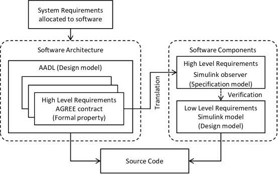
On the right side of the figure, software components are implemented and verified. Simulink models describe the detailed behaviors and are used to generate source code for each component. They are therefore considered low-level requirements and also design models (in DO-331 terms). High-level requirements for each component are represented as specification models (in DO-331 terms). These models are observers that produce a true output whenever their corresponding property (specified over the component inputs and outputs) is true. A model checker such as the one provided by Simulink Design Verifier can be used to show that the design model satisfied the high-level requirements defined by the specification model.
Clearly there is a gap between the methods, tools, and models of the software architecture and those for the software components. In the past, high-level requirements for the software components have been manually captured as observers in Simulink before they can be used for verification [10]. The manual process may be error-prone, and it can be difficult and costly to keep the models in sync. The work we describe in this paper bridges this gap by automating the translation of high-level requirements associated with the architecture model into Simulink observers that can be verified in the Simulink environment.
2.2 Architecture Description and Design Contracts
The Architectural Analysis and Design Language (AADL) [3] is a architecture modeling language for embedded, real-time, distributed systems. It was approved as an SAE Standard in 2004, and its standardization committee has active participation from many academic and industrial partners in the aerospace industry. It provides the constructs needed to model both hardware and software in embedded systems such as threads, processes, processors, buses, and memory. It is sufficiently formal for our purposes, and is extensible through the use of language annexes that can initiate calls to separately developed analysis tools.
The Assume Guarantee Reasoning Environment (AGREE) [1] is a language and tool for compositional verification of AADL models. It is implemented as an AADL annex that allows AADL models to be annotated with assume-guarantee behavioral contracts. A contract contains a set of assumptions about the component’s inputs and a set of guarantees about the component’s outputs. The assumptions and guarantees may also contain predicates that reason about how the state of a component evolves over time.
AGREE uses a syntax similar to Lustre [11] to express a contract’s assumptions and guarantees. AGREE translates an AADL model and its contract annotations into Lustre and then queries a user-selected model checker to perform verification. The goal of the analysis is to prove that each component’s contract is satisfied by the interaction of its direct subcomponents as described by their respective contracts. Verification is performed at each layer of the architecture hierarchy and details of lower level components are abstracted away during verification of higher level component contracts. This compositional approach allows large systems to be analyzed efficiently.
Component contracts at the lowest level of the architecture are assumed to be true by AGREE. Verification of these component contracts must be performed outside of the AADL/AGREE environment. In a traditional software development process, components will be developed to meet the high-level requirements corresponding to these contracts and verified by testing or code review. However, there are two problems with this approach:
-
1.
Verification methodologies like test and code review are not exhaustive. Errors in these activities can cause the compositional verification that AGREE performs to be incorrect.
-
2.
Manual translation of an AGREE contract into a property for verification at the component level can be time-consuming and error-prone.
Our solution to these problems is to automatically translate AGREE contracts of software components into expressions in the development language of the component software. A formal verification tool that reasons about artifacts expressed in this language can then be used to verify that the contracts hold. The remainder of the paper describes this solution in detail.
2.3 Component Requirements and Verification
The following tools and features are used to capture component level requirements and perform verification.
Simulink. Simulink [4], developed by MathWorks and integrated with MATLAB, provides a graphical programming environment for modeling, simulation, code generation, testing, and analysis. It is widely used in the Avionics industry. It is used to capture low-level component design models and requirements.
Simulink Design Verifier. The Simulink Design Verifier (SLDV) tool [9], provides a model checker for the Simulink environment. SLDV can verify properties expressed with MATLAB functions, Simulink blocks, or Stateflow diagrams. The first is a textual language while the last two are graphical.
Simulink observer. A Simulink observer is a component in a Simulink model which observes the behavior of another component and computes a Boolean value indicating if the latter component is satisfying its requirements. A Simulink observer along with the component it observes can be verified using SLDV to show that the component under observation always satisfies its requirements. Using DO-331 terminology, the Simulink observer is a specification model that captures high-level requirements, while the component it observes is a design model that captures low-level requirements. Our tool generates Simulink observers using a MATLAB function block which encapsulates a MATLAB function. A MATLAB function consists of statements written in the MATLAB scripting language, an imperative, dynamically typed language. In addition to a main function, a MATLAB function block can contain other local functions defined in the same block. Unlike the other graphical language alternatives, the textual representation of a MATLAB function makes the export easier to control and maintain.
3 Detailed Approach
This section details our approach for automatically constructing a specification model from high level requirements.
| AGREE Constructs | MATLAB Constructs |
|---|---|
| Component contract1 | Simulink observer |
| Component inputs and outputs1 | Inputs to the Simulink observer2 |
| Assume statement | Proof assumption |
| assume “B input range” : | sldv.assume |
| Guarantee statement | Proof objective |
| guarantee “B output range” : | sldv.prove |
| Equation statement | Assignments |
| eq | |
| If-then-else expression | Generated local function |
| AGREE basic data types | MATLAB built-in data types2 |
| int | (u)int8, (u)int16, (u)int32 |
| real | single, double |
| bool | boolean |
| Record types (on inputs and outputs) | Simulink bus objects |
| AGREE operators | MATLAB operators or function calls |
| -, not, , and, or | -, , , &&, |
| , , , , , , , | , , , , , , , |
| mod operator | mod function |
| = (equal operator) | isequal function3 |
| div (integer divide operator) | with operands typecast to integer types |
| generated local | |
| generated local 4 | |
| persistent variable for the operand4 | |
| 1 This information comes from the component type in AADL. | |
| 2 Data size selection based on user input (Section 3.3). | |
| 3 Use isequal function rather than to apply to structure types | |
| 4 The translation for and operators need persistent variables (Section 3.2). | |
3.1 Export Scheme Overview
The requirements used to generate each specification model come directly from a component contract specified in AGREE. Each specification model is a Simulink observer implemented as a MATLAB function. The observer’s interface is generated from the component’s features described in the AADL model.
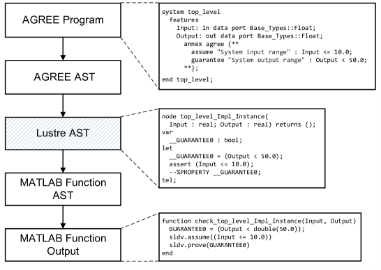
Table 1 provides a summary of the constructs that appear in an AGREE contract and their mapping in MATLAB. Our process can translate any AGREE specification. The specification model generation process is divided into two major steps, as depicted in Figure 2:
-
1.
The tool produces an intermediate specification in Lustre. The Lustre language [11] is a synchronous dataflow language for modeling reactive systems, with formalisms similar to temporal logics [12]. The AGREE grammar and the Lustre grammar are very similar. This makes Lustre well suited as a common intermediate language to feed into different formal analysis or translation engines. A number of common translation steps are performed to create this intermediate format. For example, variable assignments are put into data-flow order, all function calls are inlined, and nested temporal expressions are decoupled.
-
2.
From the intermediate Lustre a MATLAB function is produced. The MATLAB function is specified by an abstract syntax tree (AST). This allows for structured, easily extendable export. MATLAB specific features introduced in this translation include constructing valid MATLAB identifiers with no duplications and turning local structures in the intermediate output into local variables to eliminate any dynamically allocated structures.
3.2 Translation for Temporal Operations
There are two types of temporal operations used in AGREE:
-
•
The operation evaluates to its left-hand side expression when the transition system is in its initial state. Otherwise it evaluates to its right-hand side expression. For example, the expression: is in the initial state and otherwise.
-
•
The operation takes a single expression as an argument and returns the value of this expression in the previous state of the transition system. For example, the expression: constrains the current value of variable to be 0 in the initial state; otherwise it is the value of in the previous state incremented by 1.
In the model’s initial state the value of the operation on any expression is undefined. Every occurrence of a operator must be in a subexpression of the right hand side of the operator. The operation can be performed on expressions containing other operators, but there must be operations between each occurrence of a operation. For example, the expression: is not well-formed, but the expression: is well-formed.
To represent temporal constructs, the Simulink observer needs to differentiate the behavior at the initial state from the other states. It also needs to remember variable values from the previous calls to the function.
We make use of persistent variables to record the previous state of the function’s variables across multiple calls. A single persistent Boolean variable, , is used for all expressions to indicate whether or not the function is being called for the first time. Additionally, a persistent variable is created for each unique expression111For example, if the term appears multiple times in the AGREE contract, we only create a single persistent variable for this expression.. We refer to these variables as the “ variables”. The Simulink unit delay block could also be used to remember previous variable values by placing the graphical block outside of the MATLAB function for each “ variable”. However, the block needs to be placed outside of the MATLAB function, requiring any “ variable” to become an input to the function; the graphical representation also makes it harder to automate.
The persistent variables used to model the and operations appear in the following contexts in the Simulink observer:
-
1.
Declaration. Each of these persistent variables is declared at the beginning of the function. MATLAB is dynamically typed, so the type of these variables is determined during their initialization.
-
2.
Initialization. The initialization of a persistent variable occurs immediately after its declaration. The built-in function “isempty”, e.g., , is used to determine whether or not the variable has been initialized. The variables are initialized to the default value for their type (e.g., true for booleans, 0 for integers, and 0 for floating points). Because all occurrences of operators are guarded by operators, this initial value is never used. This initialization takes place for the sole purpose of allowing the Simulink code generator to function properly.
-
3.
Use. Each of these persistent variables is used in place of its corresponding expression.
-
4.
Update. Before the observer function returns, all of the variables are updated to the current value of their expression. For example, the persistent variable for the expression is updated to the value of . The variable is always set to false before the observer function returns.
3.3 Translation for Data Types
Here we note differences between the data types of AGREE and MATLAB.
Constants. Any constant numbers (integers or floats) that appear in a MATLAB function are assumed to be precision floating point numbers. Therefore, explicit typecasts are needed when translating constants from the AGREE specifications.
Arbitrary Data Size vs. Fixed Data Size. AGREE assumes that integer and real valued variables have arbitrary size. However, MATLAB’s primitive data types for integers are of bounded size (integers are represented by 8-bit, 16-bit, or 32-bit 2’s complement numbers). Integer valued variables in AGREE are translated into fixed size integers in MATLAB. Similarly, MATLAB uses floating point arithmetic to represent non-integers. Real valued variables in AGREE are translated to floating point variables in MATLAB. The size/precision of the translated variables can be changed easily by users.
This mismatch in types can cause differences in semantics for some contracts described in AGREE and their corresponding Simulink observers. Moreover, we note that SLDV interprets floating point variables as real variables as well. So it suffers from the same mismatch in semantics for floating point vs. real numbers. In the future we plan to allow users to specify bit-vector types in AGREE.
3.4 Workflow
We have implemented the export scheme as an extension to AGREE, available at [13]. The export process has the following steps:
-
1.
Select Data Types. Users may select one of the MATLAB/Simulink supported integer types (i.e., (u)int8, (u)int16, (u)int32) to represent integers from the AGREE specification and one of the MATLAB supported floating point types (i.e., single, double) to represent reals from the AGREE specification.
-
2.
Export Design Contracts. For any component with an AGREE contract, the user can invoke the tool to translate the contract into a MATLAB function.
-
3.
Update Simulink Model. A script file provided by the toolset automatically packages the MATLAB function generated above as a MATLAB function block and connects the function block to the inputs and outputs of the component’s Simulink model. The augmented Simulink model contains both a design model and a specification model that observes the design model.
-
4.
Invoke Simulink Design Verifier (SLDV). Users can invoke SLDV on the verification model generated in the above step. SLDV checks to see if all properties in the MATLAB function are true, and provides counterexamples for the ones that are falsified.
4 Case Studies
In this section, we evaluate and demonstrate the effectiveness of the export techniques in two case studies: 1) an avionics braking and steering control unit and 2) a medical infusion pump. The workflow was tested with the latest version of the AGREE toolset and MATLAB Release 2015b.
As our export tool has not yet been qualified [14], for each case study, the specification model generated by the tool is manually reviewed against the original contracts and design information in AGREE and AADL to assess if the high-level requirements have been maintained.
4.1 Avionics Braking and Steering Control Unit
Overview. The avionics Braking and Steering Control Unit (BSCU) is a computer located in an aircraft’s Wheel Braking System (WBS), controlling the “Normal braking, Autobrake, Nose Wheel Steering Aid and Antiskid functions” [15]. The specification of the BSCU came from prior verification efforts [15] based on the report of an Airbus A-320 accident which occurred on May 21, 1998 [16]. In that accident, both the normal and alternate braking systems failed on landing. The loss of the normal braking system was caused by logic disagreement in the BSCU.
The BSCU system consists of two functionally identical channels, with only one channel being active at a time. When a fault is detected in the active channel, the standby channel becomes active if it is not faulty. Each channel contains a command function unit (COM component) and a monitor function unit (MON component). Both the COM and MON components compute the braking pressure to be applied based on their braking mode. Their outputs are compared at the MON function unit, and a fault will be logged when there is a disagreement between the outputs.
The COM and MON units operate in four braking modes: MANUAL, LO, MED, MAX. In MANUAL mode, the computed breaking pressure is mainly determined by the pressure on the brake pedal applied by the pilot. Other modes are Autobrake modes selected when pilot presses one of the LO, MED, or MAX buttons on the AUTO BRK panel, providing low, medium, and maximum levels of deceleration. Each unit starts in the MANUAL mode, and can transition to another mode when the associated button is pressed once; pressing the same button again transitions the unit back to MANUAL mode.
For this specific case study, the system architecture was previously modeled in AADL, and the design contracts between the components were specified in AGREE. Prior work [15] has found a disagreement in detecting a button push between the COM and MON component. The problem was remedied by updating the design contracts in the architecture model.
For this case study, we created Simulink models for the COM and MON components. This was a manual design process to interpret the high-level requirements into a design model. The behaviors of the COM and MON models were intended to satisfy all AGREE contracts for the COM and MON components in AADL.
For each component, we exported the design contract to a Simulink observer and connected it to the corresponding Simulink model. We ran Simulink Design Verifier (SLDV) on the augmented model to discover which properties were validated and which were not. For the falsified properties, SLDV produced a counterexample.
Results and Findings. Two types of falsified properties were found during the verification process. The first type was caused by a discrepancy on the behavior of the initial step. The second type was due to a discrepancy on the value of a global parameter used to indicate if the component is currently in an active channel. In both cases, the Simulink design model failed to interpret the specific design detail as presented in AGREE. Such discrepancies were missed from the first round of manual review of the models. After updating the Simulink model to match the design contracts, all properties specified in the Simulink observer were verified.
Investigation of the counterexamples was carried out by comparing the values of the intermediate signals computed in the model and in the Simulink observer during the simulation of the counterexamples. Having the specification model and design model co-located in the same environment allowed the simulation to compare their values during runtime.
The verification results demonstrate the benefit of using formal verification over manual review or simulation/testing, as it reasons about all execution paths and identifies design flaws that can be missed by other methods.
Automatically exporting AGREE contracts to Simulink observers allows fast turn-around in verification. The verification of the Simulink design model can be conducted as soon as the model is created. This supports early and frequent verification starting from the design phase. It also reduces errors that are easily introduced from manual interpretations, especially for large components with complex contracts.
4.2 Generic Patient Controlled Analgesic Infusion Software
Overview. The Generic Patient Controlled Analgesic (GPCA) infusion pump system [10] is a medical cyber-physical system “used for controlled delivery of liquid drugs into a patient’s body according to a physician’s prescription (the set of instructions that governs infusion rates for a medication).” [10]. It allows patients to administer a controlled amount of drug (typically a pain medication) themselves. It consists of four main components: Alarm, Infusion, Mode, and Logging. They are used to monitor the exceptional conditions and notify the clinician, determine the flow of drug, manage the mode, and log the status of the system. Detailed information on GPCA requirements can be found in [17].
The workflow for this case study was similar to the BSCU case study, except that the Simulink design models for the components, as well as the Simulink observer for the properties of the design models, had been manually created in prior work [17]. In this case study, we reused the design model created for each component, and we replaced the existing (manually created) Simulink observers with the ones generated by our tool from the corresponding AGREE contracts. The updated models were then verified using Simulink Design Verifier and the verification results from both models were compared.
Results and Findings. For both the manual and auto version of the Simulink observer, the verification results identified falsified properties due to the design model not behaving as expected. The verification time between the two versions were comparable (within 10 seconds). Some properties were undecided after reaching the maximum analysis time (set at 1200 seconds) for both versions.
Although the manually created versions of the Simulink observers are still a work in progress, we can make the following observations:
-
1.
The manual properties tended to address the simpler, more straightforward contracts in AGREE, and they often missed modeling the temporal constructs from AGREE (i.e., and operators). Automation now allows us to easily translate even the complex contracts.
-
2.
The manual properties tended to lag behind the AGREE contract updates, resulting in different verification results between the manual and automated versions for the same AGREE contract. Automation makes it easy to keep all the models synchronized.
-
3.
The manual properties used Simulink unit delays outside of the MATLAB function to interpret the operator, a translation that preserves the meaning but is not easy to automate.
-
4.
The manual properties selected signals from bus elements outside of the MATLAB function, while the auto translated properties did bus element selection inside the MATLAB function. The latter is a design choice that is easier to automate and maintain.
We found the benefits of automatically connecting the created Simulink observer to the design model through a counterexample. In this counterexample, one input port to the design model and the Simulink observer was a duplicate (different port numbers and treated as different ports) instead of a replicate (same port number and treated as the same port). This made the observer not a synchronous one, and yielded different verification results from the version that had the Simulink observer auto connected.
We also found design details introduced in the Simulink model that did not conform to the interface design in AGREE. For example, for an input port of record type in AGREE, its counterpart in Simulink (of Simulink bus type) had additional elements and elements with different names. While it is understandable that the design model may introduce new details needed for the component, any new design details that affect the interface should be synchronized with the AGREE model.
5 Related Work
The idea of auto generating test cases from higher level requirements has been the subject of intensive study in both the academia and industry [18, 19, 20]. Creating properties for formal verification from higher level requirements, has been performed manually [21, 10], through patterns [22], and automatically [23, 24]. The unique contribution of our work is a method for automatically exporting high-level requirements from a system-level reasoning framework as property observers in a component-level modeling framework. This enables formal verification of the component requirements as they are developed, bridging the gap between system-level and component-level reasoning. The compositional reasoning framework OCRA [25] has similar goals as AGREE. Both frameworks reason hierarchically about a system of components with connections and contracts. However, as far as we know, there are no tools to translate OCRA contracts to observers in specification languages commonly used in the avionics industry.
6 Conclusions
In this paper we have described a method for translating design contracts for components in an AADL software architecture model into specification models that can be verified at the component level. We have provided tool support for export as Simulink observers that can be verified using the Simulink Design Verifier. Moreover, our approach is sufficiently general that other component development environments could be easily targeted. This approach is built upon the AGREE compositional analysis framework that allows verification of requirements during architecture development, prior to software component implementation. Applying the technique on an avionics system and a medical device system has shown that the design contracts from the architecture model were faithfully exported, and saved time and reduced errors compared to the manual effort. Our approach also allowed verification to proceed in parallel with software development.
Possible future work includes qualifying the export tool in accordance with avionics certification guidelines [14] and enhancing the usability of the tool by supporting automatic re-verification when design contracts are updated.
Acknowledgments.
This work was funded by NASA under
contract
NNA13AA21C (Compositional Verification of Flight Critical
Systems). We would like to thank Chad Van Fleet, Anitha
Murugesan, and Mike Whalen for their valuable feedback during this
work.
References
- [1] Cofer, D., Gacek, A., Miller, S., Whalen, M.W., LaValley, B., Sha, L.: Compositional verification of architectural models. In: Proceedings of the 4th International Conference on NASA Formal Methods. NFM’12, Berlin, Heidelberg, Springer-Verlag (2012) 126–140
- [2] Whalen, M.W., Gacek, A., Cofer, D.D., Murugesan, A., Heimdahl, M.P.E., Rayadurgam, S.: Your “what” is my “how”: Iteration and hierarchy in system design. IEEE Software 30 (2013) 54–60
- [3] Feiler, P.H., Gluch, D.P.: Model-Based Engineering with AADL: An Introduction to the SAE Architecture Analysis & Design Language. 1st edn. Addison-Wesley Professional (2012)
- [4] MathWorks: Simulink (2016) http://www.mathworks.com/products/simulink/.
- [5] RTCA DO-178C: Software Considerations in Airborne Systems and Equipment Certification, Washington, DC. (2011)
- [6] RTCA DO-333: Formal Methods Supplement to DO-178C and DO-278A, Washington, DC. (2011)
- [7] RTCA DO-331: Model-Based Development and Verification Supplement to DO-178C and DO-278A, Washington, DC. (2011)
- [8] Cofer, D., Miller, S.P.: Formal methods case studies for DO-333, NASA contractor report NASA/CR-2014-218244 (2014)
- [9] MathWorks: Simulink (2016) http://www.mathworks.com/products/sldesignverifier/.
- [10] Murugesan, A., Whalen, M.W., Rayadurgam, S., Heimdahl, M.P.: Compositional verification of a medical device system. In: ACM Int’l Conf. on High Integrity Language Technology (HILT) 2013, ACM (2013)
- [11] Halbwachs, N., Caspi, P., Raymond, P., Pilaud, D.: The synchronous dataflow programming language LUSTRE. In: Proceedings of the IEEE. (1991) 1305–1320
- [12] Huth, M., Ryan, M.: Logic in Computer Science: modelling and reasoning about systems (second edition). Cambridge University Press (2004)
- [13] Backes, J., et al.: AGREE toolset (2016) http://loonwerks.com/tools/agree.html.
- [14] RTCA DO-330: Software Tool Qualification Considerations, Washington, DC. (2011)
- [15] Miller, S.P., Bhattacharyya, S., Tinelli, C., Smolka, S., Sticksel, C., Meng, B., Yang, J.: Formal verification of quasi-synchronous systems (2015) Final Technical Report delivered Air Force Research Laboratory.
- [16] Accident, C.A., Incident Investigation Commission (CIAIAC), S.: Technical report: Accident occurred on 21 May 1998 to Aircraft Airbus A-320-21 Registration G-UKLL At Ibiza Airport, Balearic Islands (1998)
- [17] CriSys Group: Generic patient controlled analgesia infusion pump project (2016) http://crisys.cs.umn.edu/gpca.shtml.
- [18] Wang, C., Pastore, F., Goknil, A., Briand, L., Iqbal, Z.: Automatic generation of system test cases from use case specifications. In: Proceedings of the 2015 International Symposium on Software Testing and Analysis. ISSTA 2015, New York, NY, USA, ACM (2015) 385–396
- [19] Ibrahim, R., Saringat, M., Ibrahim, N., Ismail, N.: An automatic tool for generating test cases from the system’s requirements. In: Computer and Information Technology, 2007. CIT 2007. 7th IEEE International Conference on. (2007) 861–866
- [20] Escalona, M.J., Gutierrez, J.J., Mejías, M., Aragón, G., Ramos, I., Torres, J., Domínguez, F.J.: An overview on test generation from functional requirements. J. Syst. Softw. 84 (2011) 1379–1393
- [21] Miller, S.P., Tribble, A.C., Whalen, M.W., Heimdahl, M.P.E.: Proving the shalls: Early validation of requirements through formal methods. Int. J. Softw. Tools Technol. Transf. 8 (2006) 303–319
- [22] Bozzano, M., Cimatti, A., Katoen, J., Katsaros, P., Mokos, K., Nguyen, V.Y., Noll, T., Postma, B., Roveri, M.: Spacecraft early design validation using formal methods. Rel. Eng. & Sys. Safety 132 (2014) 20–35
- [23] Silva, W., Bezerra, E., Winterholer, M., Lettnin, D.: Automatic property generation for formal verification applied to hdl-based design of an on-board computer for space applications. In: Test Workshop (LATW), 2013 14th Latin American. (2013) 1–6
- [24] Soeken, M., Kuhne, U., Freibothe, M., Fe, G., Drechsler, R.: Automatic property generation for the formal verification of bus bridges. In: Design and Diagnostics of Electronic Circuits Systems (DDECS), 2011 IEEE 14th International Symposium on. (2011) 417–422
- [25] Cimatti, A., Tonetta, S.: Contracts-refinement proof system for component-based embedded systems. Science of Computer Programming 97, Part 3 (2015) 333–348