Ferromagnetic resonance and magnetic damping in C-doped Mn5Ge3
Abstract
Ferromagnetic resonance (FMR) was used to investigate the static and dynamic magnetic properties of carbon-doped Mn5Ge3 (C0.1 and C0.2) thin films grown on Ge(111). The temperature dependence of magnetic anisotropy shows an increased perpendicular magneto-crystalline contribution at 80K with an in-plane easy axis due to the large shape contribution. We find that our samples show a small FMR linewidth (corresponding to an intrinsic magnetic damping parameter =0.005), which is a measure of the spin relaxation and directly related with the magnetic and structural quality of the material. In the perpendicular-to-plane geometry, the FMR linewidth shows a minimum at around 200K for all the samples, which seems to be not correlated to the C-doping. The magnetic relaxation parameters have been determined and indicate the two-magnon scattering as the main extrinsic contribution. We observe a change in the main contribution from scattering centres in Mn5Ge3C0.2 at low temperatures, which could be related to the minimum in linewidth.
pacs:
76.50.+g,75.70.Ak,75.40.Gb,76.60.EsKeywords: ferromagnetic resonance, magnetic anisotropy, magnetic damping, thin films \ioptwocol
1 INTRODUCTION
The field of semiconductor spintronics is rapidly developing nowadays. The idea to combine the well established data processing capabilities of semiconductor electronics with ferromagnetism may lead to new functionalities and low power consumption of devices[1, 2]. One of the main obstacle for spin injection into a semiconductor is the conductivity mismatch at the interface of the ferromagnetic metal and the semiconductor[3]. One way to avoid it is to use a thin insulating layer acting as a tunnel barrier between the two materials. Another approach is to design the spin injecting interface with a similar structure and properties by alloying or doping the semiconductor with a magnetic element.
The intermetallic magnetic Mn5Ge3 could provide the desired solution as it grows directly onto Ge substrate[4], therefore being compatible with existing semiconductor technology. Mn5Ge3 shows ferromagnetism with a Curie temperature (Tc) around room temperature[5] and an important spin polarization (up to 42%)[6, 7]. The Mn5Ge3 hexagonal cell contains 10 Mn atoms which are arranged in two different sublattices (MnI and MnII) due to different coordination. Inserting carbon atoms into interstitial voids of MnII octahedra leads to an increase of Tc up to 450K, supplying a solution for the room temperature spin injection[8]. Ab-initio calculations indicate that the structural distortions have a small influence on the increased Tc in Mn5Ge3Cx (the lattice is compressed compared to pure Mn5Ge3), with the enhanced ferromagnetism attributed to a 90∘ ferromagnetic superexchange mediated by carbon[9].
Several preparation methods were used to grow Mn5Ge3 thin films. The most common growth method is the solid phase epitaxy which consists in the deposition of Mn or Mn and C on a Ge(111) layer followed by an annealing leading to the formation of the Mn5Ge3 or Mn5Ge3Cx films. Due to the low Mn solubility in Ge, secondary precipitates or Mn-rich regions/clusters frequently appear inside the Mn5Ge3 films. Mn atoms also diffuse in the underlying Ge(111) substrate which deteriorates the interface quality. In this article, we report on the structural and magnetic properties of thin films C-doped Mn5Ge3 epitaxially grown on Ge(111) by reactive deposition epitaxy (RDE) at room temperature. The low growth temperature reduces segregation and allows the formation of thin films of excellent crystalline quality suitable for the determination of various magnetic parameters by FMR: magnetic anisotropy, magnetisation and the g-factor which were quantitatively determined and theirs dependence on carbon content and temperature was identified. From the study of the FMR linewidth, the magnetic relaxation process is investigated and the magnetic relaxation parameters are found. The main relaxation channels we identify are the intrinsic Gilbert damping and the two-magnon scattering. The intrinsic magnetic damping measured by FMR determines the time scale of the dissipation of magnetic energy into the lattice. We determine that C-doped Mn5Ge3 has a very low damping of spin motions, with an intrinsic Gilbert damping constant between 0.005 and 0.01, which is one of the lowest known value for ferromagnetic Mn-based thin-film compounds. In the two-magnon scattering process, the uniform FMR mode (k=0) can scatter to degenerate non-uniform modes (k 0) with an effective interaction matrix proportional to the Fourier transform of samples inhomogeneities[10]. We observe that the role of the scattering centres changes at low temperatures in Mn5Ge3C0.2 where a superposition of twofold and fourfold symmetry dominates and not the usual six-fold as at room temperature. The ferromagnetic resonance measurements demonstrate the very good structural quality and the low magnetic damping in the C-doped Mn5Ge3, paving the way for heterostructure integration and spintronic applications.
2 Experimental details
The sample preparation as well as the reflection high-energy electron diffraction (RHEED) measurements were performed in a UHV setup with a base pressure of 2.7 Pa. Mn5Ge3Cx layers were grown epitaxially on Ge(111) substrates[4, 11]. These substrates were chemically cleaned before introduction in the UHV chamber. Then we did a degassing of the Ge(111) substrates by direct heating up to 720 K for 12 h and flashed afterwards at 1020 K to remove the native oxide layer. After repeated flashes at 1020 K and a cooling down at 770 K, a 15 nm thick Ge buffer layer was deposited on the Ge(111) substrates to make sure that the starting surface of the Mn5Ge3Cx thin films growth is of good quality. The quality of this starting surface was checked in-situ by RHEED. Eventually the sample was cooled down to room temperature (RT).
To form the Mn5Ge3Cx layers we used the reactive deposition epitaxy method[12]. Using this method the Mn5Ge3Cx layers are created by phase nucleation at the surface of the sample during the epitaxial growth. No diffusion phenomenon is required for the growth unlike the solid phase epitaxy process which is usually employed to form the Mn5Ge3Cx films on Ge(111). However a good control of the different flows is needed to match the stoichiometry of the desired compound : Ge and Mn were evaporated using Knudsen cells and C atomic flow was obtained thanks to a high purity pyrolytic graphite filament source (SUKO) from MBE-Komponenten. The Ge and Mn flows were calibrated with a water-cooled quartz crystal microbalance and the C flow was calibrated using the structure transition between the Si(001) (21) and c(44) reconstructions which occurs for a C deposited thickness of 0.4 atomic monolayer on Si(001) surfaces[13]. The growth of the Mn5Ge3Cx films was monitored in-situ by RHEED : the Mn5Ge3Cx films growing epitaxially on a Ge(111) surface exhibit an easily identifiable RHEED ()R30∘ pattern which is characteristic of the Mn5Ge3 and Mn5Ge3Cx compounds[11, 14].
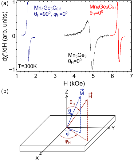
The saturation magnetisation and the estimated Curie temperatures of all samples were determined by SQUID measurements. A SQUID magnetometer Quantum Design MPMSXL working in a temperature range 1.8K to 300K and in a magnetic field up to 5T was used. The FMR measurements were performed with a conventional X-band (9.39GHz) Bruker EMX spectrometer in the 80K to 300K temperature range. The samples (mm2) were glued on a quartz suprazil rode and mounted in the centre of a rectangular cavity (TE102). To improve the signal-to-noise ratio, the FMR measurements were carried out using a modulation field of 100kHz and 5Oe amplitude with a lock-in detection. The FMR spectra were measured with the applied magnetic field rotated in plane and out-of-plane. The FMR spectra were fitted to a Lorentzian profile and the resonance field and FWHM linewidth were subsequently extracted. Typical spectra at RT are shown in figure 1(a) for 12nm thick films. The signal-to-noise ratio (SNR) of Mn5Ge3 at 300K (figure 1) is 38 which is the lowest SNR of all measured spectra and is due to the proximity to Tc. The SNRs for the other spectra of figure 1 are 115 and 250 for Mn5Ge3C0.2 and Mn5Ge3C0.1 respectively which have higher Tc.
3 Model and geometry
The FMR spectra were analyzed with the Smit-Beljers formalism for a thin film with uniaxial (hexagonal) symmetry[15]. For a ferromagnetic film with hexagonal symmetry, the free energy density including the Zeeman energy, the demagnetizing energy and the anisotropy energy density is written as:
| (1) | |||||
where , are the polar and azimuthal angle of the external field with respect to the surface normal of the thin film (the [001] direction) and, respectively, the [100] direction, and are the polar and azimuthal angle of the magnetisation with respect same directions (figure 1(b)) and Ki are the anisotropy constants to sixth order. The resonance condition, neglecting the damping effects and considering the magnetisation at equilibrium under steady field, is given by:
| (2) |
where and represent the stiffness fields evaluated at the equilibrium angles of the magnetisation:
| (3) | |||
| (4) |
Equation (2) is valid for a high-symmetry case, where the mixed second derivative of the free energy is nil. Our experiments were carried out in two distinct geometries:
-
(i)
out-of-plane geometry (, variable). The stiffness fields are the following:
(5) (6) -
(ii)
in-plane geometry (, variable). The stiffness fields are:
(7) (8)
Here , the angular frequency and = g/ the gyromagnetic ratio.
The FMR linewidth is analyzed by including the intrinsic and extrinsic damping mechanisms[16, 17, 18] :
| (9) |
In this expression, the intrinsic contribution due to the magnon-electron interaction can be described by the dimensionless Gilbert damping parameter [19, 20]:
| (10) |
where is the dragging function as the magnetisation M is dragged behind H owing to anisotropy. When M and H are parallel, this contribution vanishes. As generally the in-plane and out-of-plane linewidth are not equal, extrinsic contribution have to be taken into account. The extrinsic contribution generally include the magnetic relation due to magnon-magnon interaction, the two-magnon interaction, which is given by[21, 22, 23, 24]:
| (11) |
with the two-magnon scattering rate. The two-magnon contribution usually vanishes for a critical out-of-plane angle . Short-range fluctuations in magnetic properties due to sample imperfections lead to two-magnon scattering. Inhomogeneous broadening effects (superposition of local resonances) due to long-range fluctuations of magnetic properties also participate to the extrinsic linewidth, especially at intermediate angles as the resonance local field can vary. We consider here three types of inhomogeneous broadening: and . The first term is the mosaicity term due to the distribution of easy axes directions[16, 20]:
| (12) |
with = (). The second term represents the inhomogeneity of the internal fields in the sample[18]:
| (13) |
Finally, the last term which can contribute to the linewidth is a residual frequency and angular independent inhomogeneous linewidth that cannot be put in other form and is also due to long-range fluctuations of magnetic properties.
The procedure used to determine the magnetic parameters was as follows: the anisotropy fields were determined using the system of equations (5)-(8) applied at high symmetry directions (along easy/hard axes) together with the corresponding measured resonance fields (fixed frequency) at a fixed g-factor. Afterwards, the polar and azimuthal angular dependence of the resonance field was fitted to the same equations and the equilibrium condition of the free energy allowing for a variable g-factor as parameter. The iteration was repeated several times until a good fit was obtained. This analysis yields the g-factor, the anisotropy constants and the magnetisation direction . These values serve in the fit of the angular variation of the linewidth which allows the numerical evaluation of , and the inhomogeneous contributions using (2)-(13).
4 Results and discussion
In this section, experimental results of C-doped Mn5Ge3 thin films investigated by ferromagnetic resonance and SQUID magnetometry are presented. Using samples with different carbon content, we determined the magnetic anisotropy energy, the g-factor, magnetisation and magnetic relaxation parameters.
4.1 Magnetic anisotropy
To determine the magnetic energy anisotropy (in absolute units), FMR measurements were carried out at a frequency of 9.4GHz. The FMR spectra were recorded as a function of the polar and azimuthal angles of the external magnetic field at different temperatures. The saturation magnetisation was determined from SQUID measurements. In figure 2(d), the temperature dependence of the magnetisation up to 300K is shown for Mn5Ge3, Mn5Ge3C0.1 and Mn5Ge3C0.2. The Curie temperature was estimated from these curves using a mean-field approximation which gives a good approximation of the temperature dependence of the magnetisation. The full line correspond to a fit with the Brillouin function B1.5 (S=3/2) and the dotted line to a fit with B1 (S=1) that follows better the experimental points of Mn5Ge3C0.2. The estimated values of Tc are 315K, 345K and 450K. The error bars correspond to 10K for Mn5Ge3 and Mn5Ge3C0.1 as the experimental points cover a larger temperature range and superpose closely with B1.5. The experimental points for Mn5Ge3C0.2 cover only a small part of the temperature range and the error bars are estimated to be of 30K.
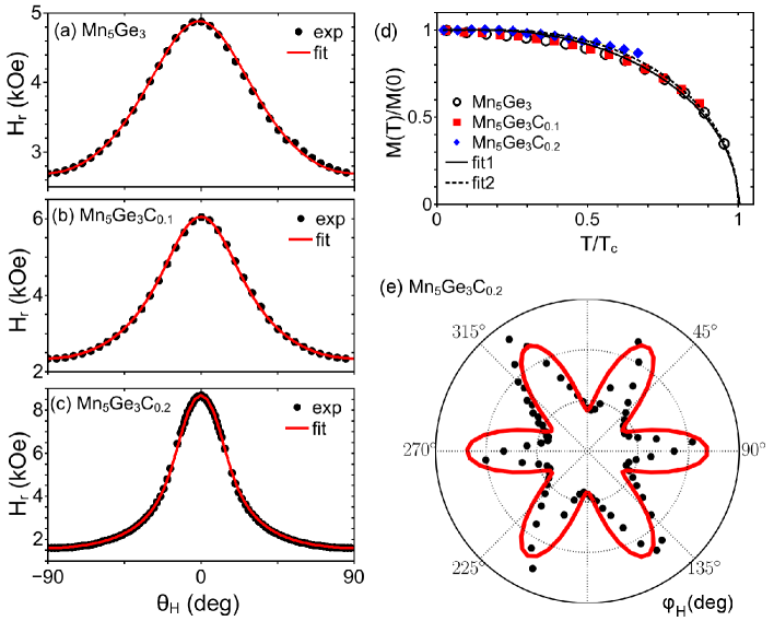
The out-of-plane angular variation for the resonance field Hr is shown in figure 2(a)-(c) for Mn5Ge3, Mn5Ge3C0.1 and Mn5Ge3C0.2 at room temperature. The Hr() curves indicate an in-plane easy axis with a minimum resonance field of 1.6kOe, 2.3kOe and 2.7kOe for Mn5Ge3C0.2, Mn5Ge3C0.1 and Mn5Ge3 respectively for . The hard axis is perpendicular to plane ([001] direction) and has the highest Hr of 8.6kOe, 6kOe and 5kOe. The azimuthal angular dependence of the resonance field for Mn5Ge3C0.2, recorded also at 300K is shown in figure 2(e). The sixfold (hexagonal) symmetry in the azimuthal angular dependence indicates that an in-plane hexagonal anisotropy exists with one easy axis along the [100] direction of the film. The experimental FMR data of out-of-plane and in-plane dependence of the resonance field can be well simulated with (2) and the anisotropy fields can be extracted. The anisotropy constants can be found in absolute units by using the sample magnetisation determined from SQUID measurements.
| Sample | T(K) | 4 Meff(kOe) | K2(erg/cm3) | K4(erg/cm3) | K6∥(erg/cm3) | (GHz/kOe) |
|---|---|---|---|---|---|---|
| Mn5Ge3 | 300 | 1.5 | 0.37 106 | 2832 | 2.8 | |
| 200 | 4.0 | 2.01 | -2.28 | 2.8 | ||
| 150 | 4.8 | 2.36 | -2.93 | 2.8 | ||
| Mn5Ge3C0.1 | 300 | 2.6 | 1.65 106 | 3.85 | 2.8 | |
| 250 | 3.8 | 2.71 106 | -1901 | 2.8 | ||
| 200 | 4.4 | 3.37 | -5131 | 2.8 | ||
| 100 | 5.0 | 4.29 | 2.58 | 2.8 | ||
| Mn5Ge3C0.2 | 300 | 5.3 | 4.39 106 | 4.41 | 27 | 2.84 |
| 250 | 5.8 | 4.78 106 | 5.53 | 134 | 2.84 | |
| 150 | 6.6 | 5.19 106 | 5.35 | 2.84 | ||
| 100 | 7.0 | 5.28 106 | 4.61 | 2.84 |
The resulting anisotropy constants are summarised in Table 1 along with the g-factor at several temperatures. The positive sign of K2 indicates that this term favors an out-of-plane easy axis of magnetisation while the shape anisotropy dominates[25]. In the very thin film limit, K2 could overcome the shape anisotropy resulting in an out-of-plane anisotropy axis. The different Ki have a different temperature dependence. For Mn5Ge3 and Mn5Ge3C0.1, the sixfold in-plane symmetry is to low to be extracted, therefore only the K2 and K4 constants were determined from the angular measurements. K2 is positive for Mn5Ge3 and C-doped Mn5Ge3 at all temperatures and increases at low temperature. K4 decreases (increases in absolute values) for Mn5Ge3, but for the C-doped compounds has a minimum or a maximum at an intermediate temperature. The sixfold in-plane anisotropy in Mn5Ge3C0.2 increases at 250K from the room temperature value, while at lower temperature becomes to small or a transition to a fourfold in-plane anisotropy arises as will be inferred from the linewidth temperature dependence discussed in the next section. The error bars for the anisotropy constants presented in Table 1 are around 5, which come from the computation of M from SQUID measurements due to the uncertainty in the volume of our samples.
The g-factor can be estimated from the angular dependence of the resonance field. Its value indicates the influence of the orbital contribution to the total magnetic moment. The ratio of the orbital to the spin magnetic moment can be inferred from the Kittel formula and is equal to the deviation of the g-factor from the free electron value. The value of the g-factor for Mn5Ge3 and Mn5Ge3C0.1 is 2.0005, while for Mn5Ge3C0.2 this value increases to 2.0291 meaning an increased orbital contribution with carbon doping (1.5% of the spin magnetic moment).
4.2 Magnetic relaxation
The linewidth of the resonant signal is directly related to the magnetic and structural quality of the films and provide information about the different relaxation channels in magnetic damping. In figure 3, the temperature dependence of the FMR linewidth is shown for the perpendicular to plane direction () for Mn5Ge3 and C-doped Mn5Ge3. A shallow minimum is observed for all three compounds around 200K and a sharp peak close to Tc. At lower temperature, the FMR linewidth increases and saturates for Mn5Ge3 (measured to 6K). The minimum in the linewidth seems not related with the C-doping. It occurs around the same absolute value of temperature and could be related with a small in-plane transition to a fourfold anisotropy from sixfold anisotropy (tetragonal distortion) or to a constriction by the substrate. The increase of linewidth at low temperature was explained as an inhomogeneous broadening due to the increase of the anisotropy constants (K2) with decreasing temperature[17]. The error bars for the measured FMR linewidth are less than 2 in all cases.
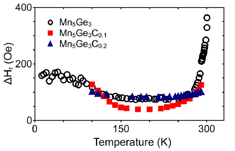
Figure 4 and figure 5(a) show the out-of-plane variation of the FMR linewidth for the C-doped Mn5Ge3 at room and low temperatures. The shape of the curves shows the characteristic dependence for thin films with a maximum of the linewidth at intermediate angles. Our films have an in-plane easy axis at all temperatures, therefore the magnetisation lags behind the applied field when the field is rotated out of the plane. The peak in the linewidth occurs for between 20∘ at room temperature and 10∘ at low temperature, corresponding to the largest interval between M and H. From the theoretical fits of the data (solid lines) obtained using (2)-(13), the relaxation parameters are extracted and listed in Table 2.
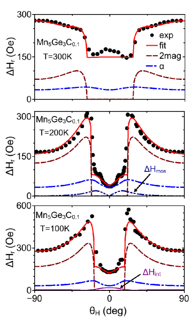
For all compounds, the perpendicular to plane linewidth is always smaller than the in-plane one indicating the presence of two-magnon scattering and other extrinsic contributions in the samples. The intrinsic damping alone cannot explain the out-of-plane shape of the dependence as observed in figure 4, where the two-magnon and intrinsic Gilbert contribution are shown individually for comparison. The respective values of the two contributions are further compared in Table 2 by computing the Gilbert damping parameter G and the two-magnon scattering contribution in s-1. The contribution of the intrinsic linewidth (Gilbert) to the total linewidth varies between 7 and 33. The mosaicity contribution is low for all cases and its angular dependence induces the V-shaped form around =0∘. A typical mosaicity contribution is shown in figure 4 for Mn5Ge3C0.1 at 200K. The inhomogeneity of the internal field gives mainly a low contribution around =0∘, with the exception of Mn5Ge3C0.1 at room temperature where it gives a larger contribution for close to the plane. A typical variation of this contribution is shown in figure 4 at 100K.
The estimated intrinsic damping is considered isotropic and independent of temperature in the considered temperature range (100K-300K). We prefer using the dimensionless parameter which varies between 0.005 and 0.01 over the Gilbert damping parameter G given by =G/M as the latter will imply a strong temperature dependence. The Gilbert damping represents the decay of magnetisation by direct viscous dissipation to the lattice as it is introduced in the Landau-Lifschitz-Gilbert equation[19]. The spin-orbit coupling is assumed to be at the origin of spin-lattice relaxation in ferromagnets. Ab-initio calculations that include the spin-orbit coupling explicitly show a weak dependence of with temperature in a large range of temperatures[26, 27]. Two different mechanisms contribute to the temperature dependence[10], one conductivity-like and one resistivity-like with a transition between the two at intermediate temperature. Sometimes these two contributions have an equal influence on the damping. Other models predict an anisotropic tensorial damping constant [28] and its proportionality to 1/M[29], leading to a strong variation close to Tc.
We estimated the value of for each compound by fitting the out-of-plane angular dependence of at a temperature corresponding to the minimum of the curves in figure 3 (around 200K). For this specific temperature, the estimation corresponds to the maximum possible value of considering small inhomogeneous broadening ( and ). Although we consider a constant , as it is observed from Table 2, at room and low temperature the linewidth (and correspondingly the inhomogeneous residual field) increases for Mn5Ge3C0.1 which could be explained by an increase of at least at low temperature. The room temperature increasing in the linewidth is usually explained as a breakdown of the uniform precession due to thermal excitations (spin-waves)[30]. The increasing of the linewidth at low temperature is smaller for Mn5Ge3 and Mn5Ge3C0.2 in the 100-300K temperature range being compatible with a constant as considered for this temperature range.
| Sample | T(K) | G(108s-1) | (Oe) | (108s-1) | (deg) | Meff)(Oe) | (Oe) | |
|---|---|---|---|---|---|---|---|---|
| Mn5Ge3 | 300 | 0.01 | 0.54 | 150 | 26.38 | 0.05 | 20 | 270 |
| 200 | 0.01 | 1.29 | 340 | 59.81 | 0.1 | 10 | 70 | |
| 150 | 0.01 | 1.41 | 550 | 96.76 | 0.1 | 10 | 10 | |
| Mn5Ge3C0.1 | 300 | 0.005 | 0.55 | 210 | 36.94 | 0.05 | 80 | 80 |
| 250 | 0.005 | 0.73 | 280 | 49.26 | 0.1 | 5 | 15 | |
| 200 | 0.005 | 0.81 | 320 | 56.29 | 0.1 | 5 | 5 | |
| 150 | 0.005 | 0.88 | 400 | 70.37 | 0.1 | 10 | 5 | |
| 100 | 0.005 | 0.92 | 430 | 75.64 | 0.1 | 15 | 70 | |
| Mn5Ge3C0.2 | 300 | 0.01 | 1.92 | 220 | 39.25 | 0.05-0.2 | 10 | 5 |
| 250 | 0.01 | 2.02 | 300 | 53.53 | 0.05 | 10 | 5 | |
| 150 | 0.01 | 2.16 | 500 | 89.22 | 0.05 | 10 | 5 | |
| 100 | 0.01 | 2.21 | 450 | 80.30 | 0.05 | 10 | 5 |
-
•
Note: The error bars are around 10.
The second relaxation mode that influence the FMR linewidth is the two magnon scattering. The uniform mode can couple with degenerate spin-wave modes due to fluctuations in the local effective field that can arise from surface defects, scattering centres, fluctuation in the anisotropy from grain to grain or other inhomogeneities[21, 23]. The two magnon scattering rate depends on the angle (out-of-plane geometry) and on the resonance field Hres. A detailed analysis based on the effect of the defects on the response functions of thin films was performed in [22] and [31] for the case when the magnetisation is tipped out-of-plane. We consider here the same type of angular dependence of as in [31] (see (8)). depends on the nature and shape of the defects that activate the scattering mechanism. The values for the Mn5Ge3 compounds, extracted from the fitting of the linewidth curves, are shown in Table 2 as a function of temperature. From the calculated value =8H, the exchange spin-wave stiffness D can be inferred if details of the defects are known such as the covered fraction of the surface or the effective height (HK the anisotropy field). Atomic force microscopy measurements were performed on the samples, from which the rms surface roughness was determined: for Mn5Ge3 the surface roughness was about 1.5-2nm, while for Mn5Ge3Cx it was close to 1nm. Therefore, at room temperature, the spin-wave stiffness was estimated as 0.12G cm2 for Mn5Ge3, 0.16G cm2 for Mn5Ge3C0.1 and 0.39G cm2 for Mn5Ge3C0.2 considering a defect ratio of 50. These values are only estimates as a precise identification of the defects is difficult to obtain.
As observed from Table 2, the other extrinsic contributions to the linewidth have only a small impact on the fitted curves. The mosaicity is very small, inferior to 0.1∘, being a testimony of the good quality of our samples. Also the inhomogeneity of the internal fields is almost negligible in the majority of cases, only for Mn5Ge3C0.1 at room temperature it seems to have a larger influence. The higher values of Hint are needed to explain the small peak observed around = 0∘ for both Mn5Ge3 and Mn5Ge3C0.1 and for the increase of the linewidth at intermediate angles until = 90∘ for Mn5Ge3C0.1 at room temperature. The values of the residual inhomogeneous contribution are generally small, the larger values can also be attributed to a temperature dependent intrinsic contribution as discussed above.
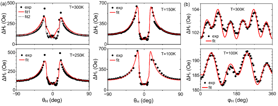
We now discuss the case of Mn5Ge3C0.2, for which both out-of-plane and in-plane data were fitted, as shown in figure 5. The panel (a) show the out-of-plane dependence of the FMR linewidth. The 300K and 250K data are well fitted close to = 0∘ and at larger angles but not at the peaks that correspond to the largest interval between M and H (critical angle). The dashed line at T=300K corresponds to a fit with the parameters indicated in Table 2 and = 0.05∘, while the full line to a fit with = 0.2∘. Although increasing the mosaicity contribution fits better the peaks, the fitted curve becomes V-shaped between the peaks in total contradiction with the data. We believe that the mosaicity is small (0.05∘) and the discrepancy at the critical angle at 300K is due to some other effect (the FMR line being strongly distorted at this angle). We also tried to fit the 300K curve introducing in-plane second and fourth order anisotropy constants (K2∥ and K4∥) without a better result (not shown). The low temperature curves are nicely fitted with the presented model for all angles.
| T(K) | (Oe) | (Oe) | (Oe) | (Oe) | |||
|---|---|---|---|---|---|---|---|
| 300 | 72.75 | 1.5 | 1.5 | 90 | 30 | ||
| 250 | 97.5 | 1.7 | 1.5 | 90 | 30 | ||
| 150 | 254.2 | 8.6 | 5.5 | 57 | 166 | ||
| 100 | 291.4 | 12.4 | 8.6 | 57 | 167 |
For the in-plane dependence of , the only contributions that were considered were from the isotropic intrinsic damping and the two-magnon contribution which was expressed as follows[21, 20, 31]:
| (14) |
with and characterise the anisotropy of the two-magnon scattering along different crystallographic in-plane directions. At 300K and 250K (figure 5(b)), the FMR linewith has the same six-fold symmetry as the angular dependence of (figure 2(e)). If the scattering centres are given by lattice defects (dislocation lines), the azimuthal dependence should reflect the lattice symmetry[32, 20]. The angular dependence of the scattering was fitted with at 250K and 300K and with at 150K and 100K. The parameters and are phenomenologically introduced to account for the observed angular variation. is expected from the sixfold symmetry. The in-plane anisotropies are very small as observed form their values in Table 1, therefore and the dragging function is very close to unity and neglected. A change of symmetry of the scattering (or of the dominant contribution to the scattering) seems to take place around 200K corresponding to the minimum in figure 3. At lower temperature a superposition of twofold and fourfold symmetry dominates the angular dependence of the in-plane linewidth. This can be related to the shape and orientation of the defects (rectangular) that cause the two-magnon scattering[21, 32, 33]. The two-magnon scattering intensity depends on the direction of the magnetisation in respect to the symmetry axes of the magnetic defects and on the angle between the magnetisation and the crystallographic axes. One can think that the twofold and fourthfold symmetry can be related to the magnetic symmetry of the defects and to the lattice defect symmetry at low temperature with the defects oriented mostly along the [110] direction. This is also consistent with the increase in the two-magnon scattering rate (see Table 2 and Table 3) at lower temperature and with the variation in the two-magnon linewidth contribution to the total linewidth (from around 30 at 300K to 66 at 100K).
5 Conclusion
12nm thick Mn5Ge3 and Mn5Ge3Cx films were grown by reactive deposition epitaxy on Ge(111) substrates. Detailed FMR measurements were performed on the samples at different temperatures. Both Mn5Ge3 and C-doped Mn5Ge3 show perpendicular uniaxial magneto-crystalline anisotropy and an in-plane easy axis of magnetisation due to the large shape anisotropy. Doping with carbon increases the anisotropy fields without diminishing the quality of the sample as demonstrated by the small FMR linewidth of the films. From the angular dependence of the resonance field and of the linewidth, the anisotropy fields, g-factor and magnetic relaxation parameters are obtained. The contributions to the broadening of the FMR linewidth come primarily from the intrinsic Gilbert damping and two-magnon scattering. In the temperature dependence of the out-of-plane linewidth a very shallow and wide minimum is observed close to 200 40K. One can suppose that this minimum and the changing of the dominating contribution in the two-magnon scattering from centres with different symmetry are connected one to each other. Nevertheless this supposition requires additional evidences.
References
References
- [1] I. Zutic, J. Fabian, and S. D. Sarma, Rev. Mod. Phys. 76, 323 (2004).
- [2] D. D. Awschalom and M. E. Flatté, Nature Phys. 3, 153 (2007).
- [3] G. Schmidt, D. Ferrand, L. W. Molenkamp, A. T. Filip, and B. J. van Wees, Phys. Rev. B 62, R4790 (2000).
- [4] C. Zeng, S. C. Erwin, L. C. Feldman, A. P. Li, R. Jin, Y. Song, J. R. Thompson and H. H. Weitering, App. Phys. Lett. 83, 5002 (2003).
- [5] M. Gajdzik, C. Sürgers, M. Kelemen, and H. v. Löhneysen, J. Magn. Magn. Mater. 221, 248 (2000).
- [6] R. P. Panguluri, C. Zeng, H. H. Weitering, J. M. Sullivan, S. C. Erwin, and B. Nadgorny, Phys. Status Solidi B 242, R67 (2005).
- [7] S. Picozzi, A. Continenza, and A. J. Freeman, Phys. Rev. B 70, 235205 (2004).
- [8] C. Sürgers, G. Fischer, P. Winkel, and H. v. Löhneysen, Phys. Rev. B 90, 104421 (2014).
- [9] I. Slipukhina, E. Arras, P. Mavropoulos, and P. Pochet, Appl. Phys. Lett. 94, 192505 (2009).
- [10] B. Heinrich, Ultrathin Magnetic Structures III (Springer, New York, 2005).
- [11] S. Olive-Mendez, A. Spiesser, L.A. Michez, V. Le Thanh, A. Glachant, J. Derrien, T. Devillers, A. Barski, M. Jamet, Thin Solid Films 517, 191 (2008).
- [12] M. Petit, L. Michez, C.-E. Dutoit, S. Bertaina, V. O. Dolocan, V. Heresanu, and V. Le Thanh, Thin Solid Films 589, 427 (2015).
- [13] L. Simon, M. Stoffel, P. Sonnet, L. Kubler, L. Stauffer, A. Selloni, A. De Vita, R. Car, C. Pirri, G. Garreau, D. Aubel, and J. L. Bischoff, Phys. Rev. B 64, 035306 (2001).
- [14] C. Zeng, W. Zhu, S. C. Erwin, Z. Zhang, and H. H. Weitering, Phys. Rev. B 70, 205340 (2004).
- [15] M. Farle, Rep. Prog. Phys. 61, 755 (1998).
- [16] C. Chappert, K. L. Dang, P. Beauvillain, H. Hurdequint, and D. Renard, Phys. Rev. B 34, 3192 (1986).
- [17] W. Platow, A. N. Anisimov, G. L. Dunifer, M. Farle, and K. Baberschke, Phys. Rev. B 58, 5611 (1998).
- [18] S. Mizukami, Y. Ando, and T. Miyazaki, Jpn. J. Appl. Phys. 40, 580 (2001).
- [19] T. L. Gilbert, IEEE Trans. Magn. 40, 3443 (2004).
- [20] K. Zakeri, J. Lindner, I. Barsukov, R. Meckenstock, M. Farle, U. von Hörsten, H. Wende, W. Keune, J. Rocker, S. S. Kalarickal, K. Lenz, W. Kuch, K. Baberschke, and Z. Frait, Phys. Rev. B 76, 104416 (2007).
- [21] R. Arias and D. L. Mills, Phys. Rev. B 60, 7395 (1999).
- [22] P. Landeros, R. E. Arias, and D. L. Mills, Phys. Rev. B 77, 214405 (2008).
- [23] R. D. McMichael, D. J. Twisselmann, and A. Kunz, Phys. Rev. Lett. 90, 227601 (2003).
- [24] S. S. Kalarickal, P. Krivosik, J. Das, K. S. Kim, and C. E. Patton, Phys. Rev. B 77, 054427 (2008).
- [25] A. Truong, A. O. Watanabe, T. Sekiguchi, P. A. Mortemousque, T. Sato, K. Ando, and K. M. Itoh, Phys. Rev. B 90, 224415 (2014).
- [26] K. Gilmore, Y. U. Idzerda, and M. D. Stiles, Phys. Rev. Lett. 99, 027204 (2007).
- [27] H. Ebert, S. Mankovsky, D. Ködderitzsch, and P. J. Kelly, Phys. Rev. Lett. 107, 066603 (2011).
- [28] V. L. Safonov, J. Appl. Phys. 91, 8653 (2002).
- [29] C. Vittoria, S. D. Yoon, and A. Widom, Phys. Rev B 81, 014412 (2010).
- [30] Yi Li and K. Baberschke, Phys. Rev Lett. 68, 1208 (1992).
- [31] J. Lindner, I. Barsukov, C. Raeder, C. Hassel, O. Posth, R. Meckenstock, P. Landeros, and D. L. Mills, Phys. Rev B 80, 224421 (2009).
- [32] G. Woltersdorf and B. Heinrich, Phys. Rev. B 69, 184417 (2004).
- [33] K. Lenz, H. Wende, W. Kuch, K. Baberschke, K. Nagy and A. Janossy, Phys. Rev. B 73, 144424 (2006).