Throughput and Coverage for a Mixed Full and Half Duplex Small Cell Network
Abstract
Recent advances in self-interference cancellation enable radios to transmit and receive on the same frequency at the same time. Such a full duplex radio is being considered as a potential candidate for the next generation of wireless networks due to its ability to increase the spectral efficiency of wireless systems. In this paper, the performance of full duplex radio in small cellular systems is analyzed by assuming full duplex capable base stations and half duplex user equipment. However, using only full duplex base stations increases interference leading to outage. We therefore propose a mixed multi-cell system, composed of full duplex and half duplex cells. A stochastic geometry based model of the proposed mixed system is provided, which allows us to derive the outage and area spectral efficiency of such a system. The effect of full duplex cells on the performance of the mixed system is presented under different network parameter settings. We show that the fraction of cells that have full duplex base stations can be used as a design parameter by the network operator to target an optimal tradeoff between area spectral efficiency and outage in a mixed system.
Index Terms:
Full duplex, small cells, stochastic geometry, outage, area spectral efficiency.I Introduction
Recent advances in hardware development [1, 2, 3, 4, 5] have enabled radios to transmit and receive on the same frequency at the same time, with the potential of doubling the spectral efficiency. Referred to as Full Duplex (FD), these systems are emerging as an attractive solution to the shortage of spectrum for the next generation of wireless networks [6, 7].
Although FD has the capability of enhancing spectral efficiency, simultaneous downlink and uplink operations on the same band generate additional interference, which is likely to erode the performance gain of FD cells [8, 9]. In this work we focus on a mixed multi-cell system, where only some of the base stations (BSs) operate in FD mode, while the remaining BSs are in half duplex (HD) mode [8, 9, 10]. Using a stochastic geometry-based model that we propose, we investigate the impact of FD cells on the performance of such mixed systems. In particular, we analyze the throughput vs. coverage trade-off of the mixed system as a function of the proportion of FD cells, and for various network parameters such as self-interference cancellation (SIC) levels, and transmit power levels at the BS and at the user equipment (UE).
I-A Background and related work
To successfully achieve SIC, which is required in order to enable FD operation, the FD circuit has a higher cost and power usage. For this reason, it is more practical to implement FD transmission on the infrastructure devices only, whereas the UE operates in HD mode [9]. An example of this is shown in Fig. 1, where each BS has two UEs scheduled at the same time on the same frequency; one is in uplink, other one is in downlink.
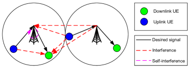
As we can note from Fig. 1, in the uplink, a BS receives interference from UEs transmitting in the uplink as well as from BSs of the neighboring cells transmitting in the downlink. It also receives the residual self-interference, generated by the same BS. In the downlink, a UE receives interference from neighboring BSs as well as from all UEs transmitting in the uplink direction. Thus, during FD operation, each direction receives higher interference compared to the HD case. For example, in a HD synchronized system, where in each timeslot all the cells schedule transmission the same direction, the downlink UE receives interference only from the neighboring BSs, and in the uplink the BS receives interference only from uplink UEs of neighboring cells. As a result of the high interference, FD systems not only cannot achieve their potential spectral efficiency gain, but can suffer from high outage probability.
Mixed multi-cell systems [8, 9, 10], in which only a given fraction of cells operate in FD mode, have been proposed in order to maintain the interference within a moderate level during FD operations. Although FD cells have the potential of enhancing the area spectral efficiency (ASE) of the network, they also increase the interference, with a consequent drop in terms of coverage.
Among the existing papers addressing FD for wireless networks in multi-cell scenarios, to the best of our knowledge, there is no comprehensive study yet that addresses the ASE vs. coverage trade-off in mixed systems, for both the uplink and the downlink directions. For instance, some works on stochastic geometry for FD operation in wireless networks have been proposed in [11, 12, 10, 13]. Tong et al. [11] investigated the throughput of a wireless network with FD radios using stochastic geometry, but in an ad-hoc setting. Alves et al. [12] derived the average spectral efficiency for a dense small cell environment and showed the impact of residual self-interference on the performance of FD operation. Lee et al. [10] derives the throughput of a mixed multi-cell heterogenous network consisting of only downlink and/or FD BSs; however, this work only focuses on the downlink, while the uplink performance is not considered. An alternative approach to a multi-cell network with FD operation in each cell is considered in [13], where the authors proposed a scheme which allows a partial overlap between uplink and downlink frequency bands. In [13], it is shown that the amount of the overlap can be optimized to achieve the maximum FD gain. However, all the papers mentioned above: [12, 10, 13] assume the UEs to have FD capabilities, which is neither practical nor economical, given existing FD circuit designs [5]. Moreover, most of the existing work investigates the ASE, while increase in outage probability is not taken into account as a metric to assess the system.
I-B Contribution
In this paper, we consider a mixed multi-cell system, in which BSs can operate either in FD or in HD mode, while UEs only operate in HD mode. The main contributions of our work are, (i) we propose a model based on stochastic geometry that allows us to characterize the outage probability and the ASE of both BSs and UEs, for both FD and HD cells; (ii) we investigate the ASE vs. coverage trade-off of mixed systems for different network parameters and we aim at finding the proportion of FD BSs such that some given constraints in terms of ASE or, alternatively, of coverage, can be met.
Among our main findings, we show that the fraction of FD cells can be used as a design parameter to target different ASE vs. coverage trade-offs for the network operator; in particular, by increasing the amount of FD cells in the mixed system, the overall throughput increases at the cost of a drop in terms coverage, and vice-versa.
II System Model
We consider a network of small cell BSs deployed according to a homogeneous and isotropic Spatial Poisson Point Process (SPPP) with density . We also consider a set of UEs, whose locations can be modeled as a SPPP with density , where . The BSs are assumed to be capable of FD operation, while the UEs are limited to HD operation. We focus on a single LTE subframe, where all cells are assumed be synchronized in terms of subframe alignment. At any subframe in any cell the BS can either be in FD mode or HD mode. In the case of HD mode the transmission can be either in downlink direction or in uplink direction.
We assume that each UE, either in the uplink or in the downlink, is served by the nearest BS. This deployment of BSs create a Voronoi tessellation with several cells, each represented by the Voronoi region around the BS location. We further assume that each FD BS will have one uplink UE and one downlink UE scheduled simultaneously at the same subframe whereas each downlink HD BS will have one downlink UE and each uplink HD BS will have one uplink UE active at their subframe.
We define , , and as the probability of a BS to be in FD mode, downlink HD mode, and uplink HD mode, respectively, with . From the “Thinning theorem” [15, Sec 2.36], the locations of the FD BSs, of the downlink HD BSs, and of the uplink HD BSs follow the SPPP, which we denote as , , and and have densities , , and , respectively; furthermore, we assume the processes , , and to be independent of one another.
Because of the assumptions of our system model, at most two UEs per cell are active, one in HD cells and two in FD cells. In other words, among all the UEs in the network, we focus our analysis only on narrow subsets of ; specifically, we consider: (i) the set of downlink and uplink UEs served by the FD BSs, namely and , respectively; (ii) the subset of downlink and uplink UEs served by the HD BSs, namely and , respectively. Due to the association strategy used to assign the UEs to a given cell , , , and are not SPPPs. Nonetheless, to maintain the mathematical tractability, we approximate these subsets as SPPP; this has been proved a good approximation in [16, 14]. From the “Thinning theorem” [15, Sec 2.36], we can obtain the densities of these subsets. To summarize, below we report the definitions of the active UEs’ subsets with the related densities.
-
•
, with density , is the subset of active downlink UEs served by the FD BSs;
-
•
, with density , is the subset of active uplink UEs served by the FD BSs;
-
•
, with density , is the subset of active downlink UEs served by the HD BSs;
-
•
, with density , is the subset of active uplink UEs served by the HD BSs.
For ease of notation, we consider the set of all active UEs, which is the union ; is assumed to be an SPPP and its density is the sum of each subset’s density, which is ( + 1) [17, Preposition 1.3.3].
Note that, the set of interfering UEs and BSs would be correlated due to the association technique mentioned above. However, to maintain model tractability, we assume that the set of interfering UEs is independent of the set of interfering BSs; this assumption has been proved to provide a good approximation for the results in previous works [12, 13]. Moreover, we also assume the SPPPs , , , and to be independent of one another and independent of , , and .
II-A Channel model
In our analysis, we model the different links with different parameters. In general, BSs and UEs are different kinds of nodes in terms of antenna height, antenna characteristics, mobility, etc. For example, different channel models are recommended by 3GPP for BS-to-BS, BS-to-UE, and UE-to-UE links [18]. We considered the following path loss models for the different links that exist in our system:
-
•
BS-to-UE path loss .
-
•
UE-to-BS path loss .
-
•
UE-to-UE path loss .
-
•
BS-to-BS path loss .
where , , and are the path loss exponents; , , and are the signal attenuations at distance = 1. We further assume that the propagation is affected by Rayleigh fading, which is exponentially distributed exp() with mean . In the next subsections, we use , , , and to denote Rayleigh fading for the BS-to-UE link, UE-to-UE link, BS-to-BS link, and UE-to-BS link, respectively.
II-B BS and UE Transmit Power Allocation
We model downlink transmission with a fixed power transmission scheme. All the BSs transmit with power . For uplink modeling, we use distance-proportional fractional power control [16], in which each UE, which is at distance from its serving BS transmits with power , where is the power control factor. If , the path loss is completely compensated, and if all UEs transmit with the same power . Both antennas at the BS and at the UE are assumed to be isotropic.
III SINR Distributions
In this section we present the analytic results for signal to interference and noise ratio (SINR) distributions in our mixed system for both downlink and uplink. We are interested in evaluating the SINR Complementary Cumulative Distribution Function (CCDF), which can written as
| (1) |
where denotes the SINR, denotes the expectation over , is the Probability Density Function (PDF) of the distance of the receiver of interest to the transmitter.
We focus the analysis on the typical receiver, either the UE or the BS, depending on whether we consider the downlink or the uplink, respectively. We differentiate the SINR expression for the downlink and the uplink in Section III-B and III-C, respectively.
III-A Probability Density Function of the Distance to the Closest Transmitter
It is known from the literature that the distance of a given point to the closest point of an SPPP with density has the following PDF [15, 19]:
| (2) |
We recall from Section II that in our system model we assume two sets, one for the set of BSs (i.e., ), the other for the set of active UEs (i.e., ). Although we assume the independence between and , some correlation exists between them. Moreover, would not be an SPPP, despite we assume it to be as such to maintain the mathematical tractability. Because of this, equation (2), which models the PDF for SPPPs, might not model accurately the PDF of the distance from a UE (i.e, any point of ) to the closest BS (i.e. a point of ). A solution to this problem has been proposed by the authors in [14], who suggested to replace (2) with the following function:
| (3) |
where is a correction factor that takes into account the effect of the correlation among points on the distance distribution; specifically, the authors of [14] have proposed to use 1.25 as a value of . One should note that (2) can be obtained as a special case of (3) for . The CDF corresponding to (3) is the following:
| (4) |
III-B Downlink SINR in a FD Cell of the Mixed System
The SINR at a downlink UE of interest in a FD cell of the mixed system, is given by
| (5) |
where is the thermal noise power at the downlink UE, and is the received signal power at the downlink UE from its serving BS, which is given by
| (6) |
where is the distance between the downlink UE and its serving BS. The serving BS is indicated by , and denotes the Rayleigh fading affecting the signal from the BS . and are the total interference received at the downlink UE from all the downlink transmissions, and from all the uplink transmissions, respectively. The total interference from all the downlink transmissions including all FD cells () and all HD downlink cells () can be defined as
| (7) |
where is the distance of the downlink UE from the neighboring active BS , and denotes the Rayleigh fading for this link. Similarly, is the sum of interference from the uplink transmission of FD cells and HD uplink cells,
| (8) |
where the general uplink UE , (i) is located at distance from its serving BS; (ii) transmits with power ; (iii) is at distance from the downlink UE of interest. The symbol denotes the Rayleigh fading for the channel between uplink UE and the downlink UE of interest.
III-B1 Downlink SINR CCDF
By using (5) and (6), we can define,
| (9) |
where (a) follows from the fact that . The Laplace transform of the total interference , , where , can be written as
| (10) | ||||
Using the independence among , , , and mentioned in Section II, we can separate the expectation to obtain:
| (11) | ||||
The first term can be further written as
| (12) | ||||
By applying the Probability Generating Functional (PGFL) [15] of the SPPP to (12), it can be further written as:
| (13) |
Similarly the second term in (11) can be written as:
| (14) | ||||
Note that in (13), the lower extreme of integration is because the closest interferer BS (either FD or HD) from the FD downlink UE of interest is at least at a distance . However, the closest uplink UE interferer of a FD cell can also be in its own cell, so the lower extreme of integration in (14) is zero. Under the special case of no power control , expression (14) is converted to:
| (15) |
III-C Uplink SINR in a FD Cell of the Mixed System
The SINR for the uplink UE of interest in a FD cell of the mixed system, is given by
| (17) |
where is the received signal power from the uplink UE of interest to its serving BS, which is given by
| (18) |
where is the distance between the uplink UE and its serving BS, and denotes the Rayleigh fading for this link. In (17), is the thermal noise power at the BS receiver and is the residual self-interference at the BS, which depends on the transmit power of the BS, . We model the residual self-interference as Gaussian noise, the power of which equals the ratio of the transmit power of the BS, , and the amount of SIC [9].
In (17), and are the total interference received at the BS from all the downlink transmissions, and from all the uplink transmissions, respectively. These can be defined as
| (19) |
| (20) |
where and are the distances of the BS from its neighboring BS and the active uplink UE in a neighboring cell, respectively; is the distance of the UE from its serving BS. As proposed in [14], the condition in (20) for all guarantees that the distance of the interfering UE to its serving BS is shorter than the distance from to the victim BS.
III-C1 Uplink SINR CCDF
The CCDF for the uplink SINR, , is given by,
| (21) |
By using the similar steps described in Section III-B1,
| (22) | ||||
where the Laplace transform of , assuming , is given by
| (23) | ||||
The first term in (23) can be further written as,
| (24) |
The lower extreme of integration in the above term is zero because the closest interferer BS (either FD or HD) can be at any distance greater than zero. The second term can be further written as:
| (25) | ||||
The lower extreme of integration in the above term is also zero but the constraint makes sure that only active UEs from the other cells are included in the interference term. The terms in expression (25) are further solved in Appendix B. Under the special case of no power control (), the above expression can be written as:
| (26) |
where is given in (4). Finally, by plugging (22) in (21), we obtain the CCDF of the uplink SINR in a FD cell for a mixed system.
| (27) |
where , and is given by (3); note that we will determine the value to be used for the parameter of be used for the parameter (3) in Appendix A, where we will compare the analytical model with simulation results.
III-D Downlink and Uplink SINR in the HD Cells of the Mixed System
The downlink SINR at a UE in a HD cell of the mixed system can be derived similarly to the downlink SINR in a FD cell. A downlink UE in a HD cell gets interference from all simultaneous uplink and downlink transmissions similar to the downlink UE in a FD cell. However, there will one difference from the derivation of the SINR CCDF given in Section III-B1. To consider the interference from all the active uplink transmissions, the lower extreme of integration in (14) is zero, which includes the uplink transmission in its own FD cell, whereas in the case of a HD cell, we need to make sure that no uplink transmission inside the downlink UE’s own cell is included. For analytical tractability, to take this into account, we make an approximation that the distance from the nearest interfering uplink transmission is approximated by the distance from the nearest interfering BS. This is the same approximation made in [10, 13] while modeling the UE-to-UE interference at a FD UE.
Thus, in this case, the lower extreme of integration in (14) will be , i.e., the distance of the downlink UE from its serving BS. For this case,
| (28) | ||||
In the uplink case, the expression for uplink SINR in a HD cell will be given as the uplink SINR in a FD cell in Section III-C but without any self-interference, i.e., ,
| (30) |
IV Average rate
In general, the average rate per hertz can be computed as follows [16].
| (33) |
By applying this, we can derive the average rate for the downlink and uplink in both FD and HD cells. By using (1), and (9), the average downlink rate in the FD cell is given by
| (34) | ||||
Similarly the average downlink and uplink rates in a HD cell, i.e, , , respectively, can be derived.
Combining the rates of FD and HD cells, the average downlink and uplink rates of the complete network are given by, respectively,
| (36) |
| (37) |
V Numerical Results
The formulation we presented in Section III has been obtained using some approximations that allow us to keep the mathematical tractability of the model, so that to obtain the SINR CCDF for the downlink and uplink. Before being used, though, our model needs to be validated, in order to ensure that it can provide trustable results. We use some simulations to generate the expected SINR CDF curves for both the downlink and uplink, and to match the analytical curves. The model benchmark can be found in the Appendix A, which the reader can refer to for further details.
This benchmark serves also as tool to determine what value of should be used for the analytical model (see Section III-A). It turns out that, in the downlink, gives a better match, while provides better results for the uplink case. Therefore, in the following sections, we will use and to compute the numerical results for the downlink and for the uplink, respectively.
We evaluate the throughput of the proposed mixed system, and present the effect on it of network parameters such as SIC, and the transmit powers of BS and UEs. The performance of the mixed system is also compared with a traditional synchronous TDD half duplex system (THD System), in which, (1) in a given time slot, all cells schedule either uplink or downlink transmission, and (2) the number of time slots is divided equally between the uplink and downlink transmission. In this case, a downlink transmission receives interference from only the neighboring BSs and an uplink transmission receives interference from only the uplink transmissions of the neighboring cells.
| Parameter | Value |
|---|---|
| Bandwidth | MHz |
| BS Density [nodes/m2] | |
| Thermal Noise Density | dBm/Hz |
| Noise Figure | dB (UE), dB (BS) |
| Path Loss (dB) ( in km) [20] | |
| Outage SINR Threshold | dB |
Please note that in our analysis in Section III we considered a general model where all the links have different channel parameters and the uplink has power control, however, in this section, we generate results for the specific case of using the same channel parameters for all the different links. The effect of different channel parameters for different links is left as future work. Moreover, we also assume that all uplink UEs transmit with the same power (), i.e., . We observed that power control modeled as in Section II-B with considerably lowers the uplink performance. This is due to the interference generated by the BSs, which do not implement any downlink power control. In HD networks with uplink power control, the UEs close to the BS reduce their transmit power and so does the interference on other cells’ uplink UEs; as a result, the cell-edge UEs’ SINR improve. In contrast, in a FD network, even though the UEs close to the BS reduce their transmit power, the interference of the BS remain unchanged and, therefore, the UEs’ SINR drops considerably, because the reduction of the received power is not compensated by a corresponding reduction of the interference. We reckon that an appropriate power control in FD networks is a challenge that should be addressed, and it will be considered in our future work.
We simulate a dense small cell network, for which the network parameter values are described in Table I. With this setting we generate the following numerical results. Figs. 2 and 3 show the ASE of the mixed system as a function of the percentage of FD BSs () with different SIC. The remaining BSs are equally divided into HD downlink and HD uplink modes, i.e., . The transmit power of the BS and the UE are fixed to 24 dBm, and 23 dBm, respectively.
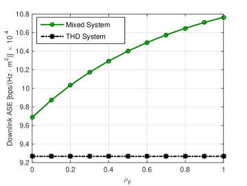
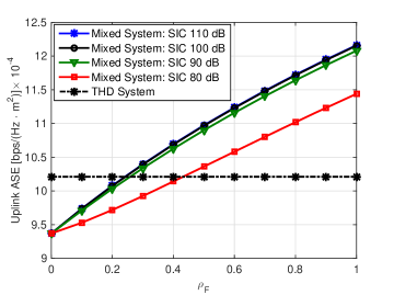
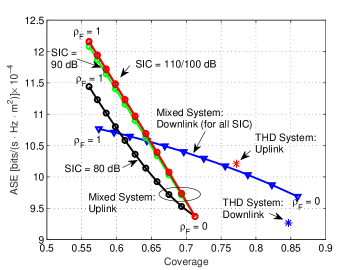
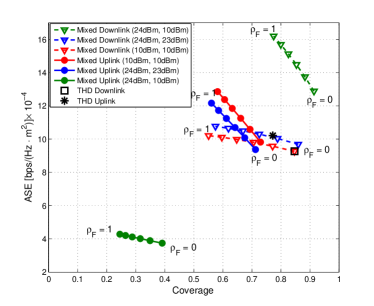
In the mixed system, as we increase the number of BSs in FD mode, both downlink and uplink ASE increase. As we increase , both the number of transmissions and the aggregated interference in each direction increase, which generates a tradeoff between ASE and the coverage as shown in Fig. 4. We define coverage as the fraction of UEs in a non-outage region, where an outage happens if the received SINR goes below the outage SINR threshold. The increasing number of transmissions provides higher ASE as shown in Figs. 2 and 3, but a higher outage as well as shown in Fig. 4. The higher ASE gain is therefore achieved at the cost of lower coverage. Thus an appropriate ratio of FD BSs, reflecting a desired optimal tradeoff between these two conflicting objectives, should be enabled in the network.
As shown in Fig. 2, the throughput of the downlink direction is not affected by the SIC, because self-interference is received only in the uplink transmission. In the uplink direction, as shown in Fig. 3, the gain of the mixed system increases as SIC improves. It can also noted that there is no improvement in the uplink performance after reducing SIC below 100 dB, because for this dense multi small cell network, after some point inter-cell interference starts dominating the total interference in the uplink direction.
Moreover, Fig. 3 shows that in the uplink direction, the mixed system is superior to THD system when the percentage of BSs in FD mode is higher than 25%-45%, depending on the SIC value, which is not the case in the downlink direction. For lower values of , in the mixed system most of the cells are in HD mode, similar to the THD system. However, in the mixed system the uplink transmission receives BS-to-BS interference from the cells, which are in HD downlink mode. This interference is generally stronger than the UE-to-BS interference, which decreases the throughput of the mixed uplink system compared to the uplink of THD system, where only UE-to-BS interference exists. However, in the downlink case, UE-to-UE interference is generally weaker than the BS-to-UE interference, which consequently leads to higher throughput in the mixed system even for lower values of .
Figs. 5 and 6 show the impact of the transmit power of BS () and UE () on the downlink and uplink ASE. In the THD system, downlink performance depends only on because the downlink transmission receives interference only from the neighboring downlink transmissions. Similarly, the uplink performance depends only on . In the THD system, changing the transmit power does not show much variation in any direction. This is because due to the high density of the BSs, it is an interference limited regime, and changing the transmit power in any direction also proportionately changes the interference, so the SINR does not vary much.
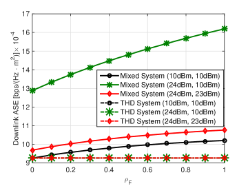
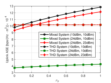
In the mixed system, both downlink and uplink performance depend on the transmit powers of both BS and UE. For the downlink case, as shown in Fig. 5, as we reduce the uplink transmit power, it reduces the UE-to-UE interference, which improves the downlink throughput. The highest downlink gain in all the computed set of transmit powers is achieved when the difference between the downlink and uplink transmit power is maximum, which is the case with = 24 dBm, and = 10 dBm in Fig. 5. By contrast, in the mixed uplink case, as shown in Fig. 6, the uplink gain improves as the difference between the downlink power and uplink power decreases. For example, in Fig. 6, the highest uplink gain is achieved when the is at the same level as .
Fig. 7 shows the tradeoff between ASE and coverage for a different set of transmit powers in downlink and uplink. The case of = 24 dBm, and = 10 dBm provides the highest downlink coverage and downlink ASE but the worst uplink coverage and uplink ASE. These results show the need of an appropriate selection of transmit powers for joint performance gain in the mixed system. In general, to achieve the maximum joint uplink and downlink gain, both uplink and downlink powers should be optimized considering downlink and uplink UEs, as well as a pool of parameters, such as the BS-to-BS, BS-to-UE and UE-to-UE channels, SIC, etc. [8]. In this paper, where we derive average analytical performance using fixed power allocation for all UEs, having similar transmit powers for BS and UE provides a fair performance to both uplink and downlink, while having unbalanced transmit powers benefits one direction at the cost of the other direction which may be a desirable outcome if the uplink and downlink traffic is asymmetric.
VI Conclusion and future work
In this paper we considered a mixed multi-cell system, composed of full duplex and half duplex cells, for which we proposed a stochastic geometry-based model that allows us to numerically assess the SINR complementary CDF and the average spectral efficiency, for both the downlink and uplink directions. Using this model, we studied the impact of FD cells on the average spectral efficiency vs. coverage tradeoff of these systems, for various transmit power values at the BS, at the UE, and for different self-interference cancellation levels.
We have shown that increasing the proportion of FD cells increases ASE but reduces coverage and, therefore, can be used as a design parameter of the network to achieve either a better ASE at the cost of limited coverage or a lower ASE with improved coverage, depending on the desired tradeoff between these two performance metrics. Moreover, we show that, in order for the downlink and uplink to achieve similar performance, the transmit power at the BS and at the UE should have similar values, but also that these powers can be tuned to achieve asymmetric uplink and downlink performance improvements if traffic demands dictate this. As future work, we will extend our study to include power control, and to different path loss models for the BS-to-BS, BS-to-UE and UE-to-UE channels.
Appendix A
In Section III we proposed a model to compute the downlink and uplink SINR CDF of a FD system in a multi-cell scenario. Due to the approximations we introduced to maintain the mathematical tractability, a benchmark of the model is required in order to prove the accuracy of the proposed formulation. In particular, we compared results obtained by numerical integration of (16) and (27) with those obtained through simulation. We neglect the self-interference and the noise and we assume that both UEs and BSs transmit with the same power. One of the goals of this benchmark is also to determine which value of should be used for the PDF of the distance to the transmitter (see Section III-A); we evaluate two values, namely = 1 and = 1.25.
We resort to as a correction factor to compensate the lack of correlation among the process of BSs and of the active UEs, which we assumed to be independent in order to keep the analytical tractability of the model proposed in Section III. Nonetheless, equation (2), which models the PDF of the distance to the closest point for SPPPs, does not reproduce the PDF of the distance to the closest point of the actual model, which is not an SPPP. The parameter allows us to adjust (2) to improve its match with the actual PDF obtained from the simulation results.
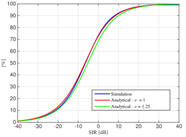
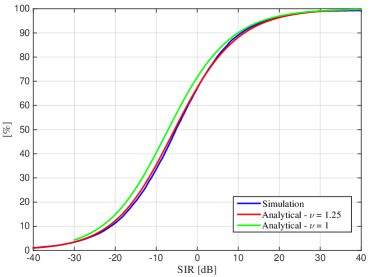
We show the match of the analytical model for the downlink and uplink with the simulation results in Figs. 8 and 9. We can notice that provides the best match for the downlink, while gives the best results for the uplink. Therefore, we will use the value to compute the numerical results for the downlink, whereas we will use for the uplink.
Appendix B
The integration in (25) can be further solved as
| (40) | ||||
where . By using integration by parts, can be written as
| (41) |
| (42) | ||||
References
- [1] A. K. Khandani, “Methods for spatial multiplexing of wireless two-way channels,” October 2010, US Patent 7,817,641.
- [2] M. Knox, “Single antenna full duplex communications using a common carrier,” in Wireless and Microwave Technology Conference (WAMICON), 2012 IEEE 13th Annual, April 2012, pp. 1–6.
- [3] D. Bharadia, E. McMilin, and S. Katti, “Full duplex radios,” in Proceedings of the ACM SIGCOMM 2013. ACM, 2013, pp. 375–386.
- [4] M. Duarte, A. Sabharwal, V. Aggarwal, R. Jana, K. Ramakrishnan, C. Rice, and N. Shankaranarayanan, “Design and characterization of a full-duplex multiantenna system for WiFi networks,” Vehicular Technology, IEEE Transactions on, vol. 63, no. 3, pp. 1160–1177, March 2014.
- [5] A. Sabharwal, P. Schniter, D. Guo, D. Bliss, S. Rangarajan, and R. Wichman, “In-band full-duplex wireless: Challenges and opportunities,” Selected Areas in Communications, IEEE Journal on, vol. 32, no. 9, pp. 1637–1652, Sept 2014.
- [6] Cisco, “Cisco visual network index: Forecast and methodology 2013-2018,” Cisco white paper, June 2014. [Online]. Available: www.cisco.com
- [7] “NGMN 5G white paper,” March 2015. [Online]. Available: www.ngmn.org
- [8] S. Goyal, P. Liu, S. Panwar, R. Yang, R. A. DiFazio, and E. Bala, “Full duplex operation for small cells,” CoRR, vol. abs/1412.8708, 2014. [Online]. Available: http://arxiv.org/abs/1412.8708
- [9] S. Goyal, P. Liu, S. Panwar, R. A. Difazio, R. Yang, and E. Bala, “Full duplex cellular systems: Will doubling interference prevent doubling capacity?” Communications Magazine, IEEE, vol. 53, no. 5, pp. 121–127, May 2015.
- [10] J. Lee and T. Quek, “Hybrid full-/half-duplex system analysis in heterogeneous wireless networks,” Wireless Communications, IEEE Transactions on, vol. 14, no. 5, pp. 2883–2895, May 2015.
- [11] Z. Tong and M. Haenggi, “Throughput analysis for wireless networks with full-duplex radios,” in 2015 IEEE Wireless Communications and Networking Conference (WCNC), Mar. 2015, pp. 717–722.
- [12] H. Alves, C. H. de Lima, P. H. Nardelli, R. Demo Souza, and M. Latva-aho, “On the average spectral efficiency of interference-limited full-duplex networks,” in 9th International Conference on Cognitive Radio Oriented Wireless Networks and Communications (CROWNCOM). IEEE, 2014, pp. 550–554.
- [13] A. AlAmmouri, H. ElSawy, O. Amin, and M. Alouini, “In-band full-duplex communications for cellular networks with partial uplink/downlink overlap,” CoRR, vol. abs/1508.02909, 2015. [Online]. Available: http://arxiv.org/abs/1508.02909
- [14] B. Yu, S. Mukherjee, H. Ishii, and L. Yang, “Dynamic TDD support in the LTE-B enhanced local area architecture,” in 2012 IEEE Globecom Workshops, Dec 2012, pp. 585–591.
- [15] M. Haenggi, Stochastic Geometry for Wireless Networks. Cambridge University Press, 2013.
- [16] T. D. Novlan, H. S. Dhillon, and J. G. Andrews, “Analytical modeling of uplink cellular networks,” CoRR, vol. abs/1203.1304, 2012. [Online]. Available: http://arxiv.org/abs/1203.1304
- [17] F. Baccelli and B. Błaszczyszyn, Stochastic Geometry and Wireless Networks, Volume 1, Theory. NOW Publishers, 2009.
- [18] 3GPP, “Further enhancements to LTE time division duplex (TDD) for downlink-uplink (DL-UL) interference management and traffic adaptation,” TR 36.828, v.11.0.0, June 2012. [Online]. Available: www.3gpp.org
- [19] J. G. Andrews, F. Baccelli, and R. K. Ganti, “A tractable approach to coverage and rate in cellular networks,” IEEE Transactions on Communications, vol. 59, no. 11, pp. 3122–3134, Nov 2011.
- [20] 3rd Generation Partnership Project (3GPP), “Further Advancements for E-UTRA Physical Layer Aspects (Release 9),” Mar. 2010, 3GPP TR 36.814 V9.0.0 (2010-03).