Disk Polarization From Both Emission and Scattering of Magnetically Aligned Grains: The Case of NGC 1333 IRAS4A1
Abstract
Dust polarization in millimeter (and centimeter) has been mapped in disks around an increasing number of young stellar objects. It is usually thought to come from emission by magnetically aligned (non-spherical) grains, but can also be produced by dust scattering. We present a semi-analytic theory of disk polarization that includes both the direction emission and scattering, with an emphasis on their relative importance and how they are affected by the disk inclination. For face-on disks, both emission and scattering tend to produce polarization in the radial direction, making them difficult to distinguish, although the scattering-induced polarization can switch to the azimuthal direction if the incident radiation is beamed strongly enough in the radial direction in the disk plane. Disk inclination affects the polarizations from emission and scattering differently, especially on the major axis where, in the edge-on limit, the former vanishes while the latter reaches a polarization fraction as large as . The polarizations from the two competing mechanisms tend to cancel each other on the major axis, producing two low polarization “holes” (one on each side of the center) under certain conditions. We find tantalizing evidence for at least one such “hole” in NGC1333 IRAS4A1, whose polarization observed at 8 mm on the 100 AU scale is indicative of a pattern dominated by scattering close to the center and by direction emission in the outer region. If true, it would imply not only that a magnetic field exists on the disk scale, but that it is strong enough to align large, possibly mm-sized, grains.
keywords:
dust - polarization - protoplanetary disks - magnetic fields1 Introduction
It is generally expected that magnetic fields play a crucial role in the dynamics and evolution of young star disks, through magneto-rotational instability (Balbus & Hawley, 1991) and magneto-centrifugal disk wind (Blandford & Payne 1982; see Turner et al. 2014 and Armitage 2015 for recent reviews). This expectation, based mostly on theoretical studies, provides a strong motivation to search for the putative disk field observationally. To date, the observational effort has been concentrated on detecting and characterizing the polarized dust continuum emission, which has long been interpreted as coming from magnetically aligned grains (Lazarian, 2007; Andersson et al., 2015), using the Submillimeter Array (SMA; Hughes et al., 2009; Rao et al., 2014) and Combined Array for Research in Millimeter-wave Astronomy (CARMA; Hughes et al., 2013; Stephens et al., 2014; Segura-Cox et al., 2015). More recently, Cox et al. (2015) opened a new front for this line of research by detecting dust polarization at 8 mm and 1 cm on the 100-AU scale around the protostar NGC1333 IRAS4A1 using The Karl G. Jansky Very Large Array (VLA), as part of the VLA Nascent Disk and Multiplicity (VANDAM) survey (Tobin et al. 2015; see also Liu et al. 2016). If the detected (sub)mm and cm polarization is indeed produced by magnetically aligned grains, it would provide the long sought-after evidence that young stellar disks are magnetized, which is a pre-requisite for MRI and magneto-centrifugal disk winds to operate.
However, Kataoka et al. (2015a) recently discovered an alternative mechanism for producing polarized millimeter emission in disks that relies on dust scattering of anisotropic incident radiation rather than the alignment of asymmetric grains. Yang et al. (2016, Paper I hereafter) showed that, in the best observed case of HL Tau disk (Stephens et al., 2014), the polarization pattern is broadly consistent with that produced by dust scattering in an inclined disk (see also Kataoka et al., 2015b), although grain alignment cannot be ruled out completely, especially if the magnetic field structure of the disk is more complex than a purely toroidal configuration (Stephens et al., 2014). If the dust scattering interpretation is correct, the grains responsible for the scattering in the HL Tau disk must be orders of magnitude larger than the classical ISM size of 0.1 m (at least several tens of microns; Paper I and Kataoka et al. 2015b). The inferred (relatively large) grain size would add to other lines of evidence for substantial grain growth in protoplanetary disks (e.g., Pérez et al. 2012; Guidi et al. 2016; see Testi et al. 2014 for a recent review), which provides a first step toward planets.
Whether large (non-spherical) grains can be aligned with respect to the magnetic field inside a protoplanetary disk remains uncertain. In the context of the currently favored mechanism for grain alignment through radiative torque, their magnetic moments may not be large enough to provide the fast precession needed (Lazarian 2007; although it depends on the disk field strength, which is uncertain), and their slow internal relaxation makes the alignment less efficient (Hoang & Lazarian, 2009). More work is needed to address this important issue. In this paper, we will adopt the conventional view that the grains are aligned with respect to the magnetic field (Andersson et al., 2015), at least to some extent in the disk, and treat the (currently uncertain) degree of alignment as a free parameter111The parametrization is also needed because of the uncertainty in the grain shape, which greatly affects the degree of polarization but cannot be determined from the grain alignment theory.. This treatment allows us to focus on the following question: how would the polarization pattern produced by direct emission from magnetically aligned grains be modified by scattering by the same aligned grains? It is a step beyond Paper I and Kataoka et al. (2015a, b), because the grains are no longer assumed to be spherical and the polarization from direct dust emission is included together with that from scattering. Our goal is to delineate the conditions under which one of the two competing mechanisms would dominate over the other and vice versa, and to determine the composite polarization pattern when both are important. This delineation of the parameter space and the determination of polarization pattern will benefit the physical interpretation of disk polarization observations, especially those to be conducted with the Atacama Large Millimeter/submillimeter Array (ALMA).
As a first step toward a comprehensive theory of disk polarization including both emission and scattering from magnetically aligned grains, we will adopt the well-known “electrostatic approximation” to simplify the computation of the optical properties of non-spherical grains. This approximation is discussed in § 2, together with an analytic model to illustrate the relative importance of the scattering and direct emission in producing polarization, which turns out to depend strongly on the disk inclination. In § 3, we compute numerically the polarization patterns of a model disk produced by the scattering and direct emission individually and in combination, to illustrate the diverse outcomes of the competition between the two mechanisms, especially for disks of different inclinations. Our results are used to explain the polarization detected in NGC1333 IRAS 4A1 in § 4. We discuss the implications of our results and their limitations in § 5, and conclude in § 6.
2 Competition between scattering and direct emission of non-spherical grains: analytic results
In order to determine how a non-spherical dust grain scatters light, one needs to know how it interacts with an external electromagnetic wave. The interaction can be very complicated in general, since each grain can be considered as a collection of polarizable parts, and each part responds to its local electric field inside the grain and may have a different polarization and phase. The grain-light interaction can in principle be treated numerically using, for example, the Discrete Dipole Approximation (e.g., Draine & Flatau, 1994). However, such numerical treatments tend to be computationally expensive, and are not optimal for an initial exploration of the problem at hand: competition between the scattering and direct emission of non-spherical, magnetically-aligned grains in determining the polarization pattern. For such a purpose, we have decided to employ the well-known “electrostatic approximation” (e.g., Bohren & Huffman 1983), which greatly simplifies the computation of the scattering cross sections without sacrificing the essential physics. The limitations of this approximation and its future refinements are discussed in section § 5 (see Fig. 7). Our discussion below follows closely that in Chapter 5 of Bohren & Huffman 1983, to which we refer the readers for details.
2.1 Electrostatic approximation
The basic requirement for the electrostatic approximation is that the grain size is smaller than the wavelength of the external electromagnetic wave. In such a case, the electric field varies little across the grain, and the field can be approximated as having the same time dependence throughout the region of interest. The approximation simplifies the calculation of the polarization of the (small) grain using the electrostatic equations with only spatial derivatives.
The scattering cross sections depend on both the size and shape of the dust grain. The grain shape is not well constrained. For illustration purposes, we model the grain as an ellipsoid, for which analytic solutions are available. For an ellipsoid composed of isotropic material with a complex dielectric constant , the governing electrostatic equations can be solved analytically using ellipsoidal coordinates. The dielectrics will respond to the external field linearly and develop a dipole moment. Since the grains are not spherical, the polarizability that relates the electric dipole moment induced in the grain to the external electric field is not a single number but rather a matrix, i.e., . In a coordinate system with axes along the three principle axes of the dust grain, the polarizability matrix is diagonal, i.e., . Its diagonal element can be expressed as:
| (1) |
where is the radius of the sphere that has the same volume as the ellipsoid, and () is a geometric parameter determined solely by the shape of the grain, subjected to the constraint . In the simplest case of a spherical grain, is . For an ellipsoidal grain, can be expressed as an integral that includes the length of the corresponding principle axis as a parameter. For an spheroid, which is an ellipsoid obtained by rotating an ellipse along one of its principle axis, the integral can be done analytically. Following the convention (which corresponds to the convention for the semi-diameters and diagonal matrix elements ), we have for a prolate spheroid ():
| (2) |
where is the axis ratio. The other two geometric parameters are both equal to .
For an oblate spheroid (), we have:
| (3) |
where the axis ratio is defined as . The other two geometric parameters are given by and .
As the external electric field varies over time, the dipole induced inside the grain also oscillates, which results in dipole radiation. It is straightforward to compute the scattering matrix and phase matrix of the induced dipole radiation and, through the optical theorem, obtain the absorption cross section. The resultant scattering and absorption cross sections will be used to compute numerically the polarization due to direct emission and scattering of (small) ellipsoidal grains in a young star disk in § 3. Before doing so, we will first illustrate the main features of the polarization produced by the scattering of non-spherical grains analytically in a limiting case, which will also allow us to compare with previous work and build physical intuition of how the scattering of non-spherical grains depends on the disk inclination, a focus of this investigation.
2.2 Inclination-induced polarization from scattering by oblate grains
In Paper I, we showed that the disk inclination with respect to the line of sight plays an important role in the polarization produced by the scattering of spherical grains. The inclination-induced polarization was illustrated analytically in the limiting case where the disk is geometrically thin and the incoming radiation to be scattered by the grains is locally isotropic in the disk plane (see their § 2.2). Under these conditions, the polarization fraction of the scattered light by small spherical grains goes from zero for the face-on view to for the edge-on case. Here, we extend this analysis to oblate grains with the semi-diameters (Hildebrand & Dragovan, 1995); the case of prolate grains will be discussed in the Appendix A.
To be specific, let us consider the polarization of the light scattered by oblate grains at a location inside a disk that is inclined with respect to the line of sight by an angle ( corresponds to the face-on case). We will adopt a Cartesian coordinate system centered on the location , with the -axis pointing radially away from the center of the disk, and -axis tangential to the circle in the disk plane that is centered at the origin and passes through the point . For simplicity, we assume that the disk magnetic field is purely toroidal, so that the only non-zero component is along the -direction. In the case of perfect grain alignment, the y-axis is also the direction of the minor axis of the oblate grain (with the smallest semi-diameter ). The -axis of the coordinate system is perpendicular to the disk plane. In this coordinate system, the polarizability is diagonal: , with , and . We let the -axis lie in the plane of the sky, so that the line of sight to the location of interest is perpendicular to the -axis and is thus in the plane. In this coordinate system, the disk inclination angle is simply the angle between the axis and the line of sight, and the -axis is along the major axis of the inclined disk projected in the plane of the sky. For this initial analysis, we focus on the disk locations on the major rather than the minor axis for two reasons. First, the polarization produced by direct emission from the oblate grains on the minor axis is independent of the inclination angle because these grains are aligned with the (toroidal) magnetic field in such a way that they always appear “edge-on” to the observer. More importantly, the polarization pattern is expected to be simpler on the minor axis because both direct emission and scattering there tend to produce polarization along the minor axis (although not always, see Fig. 3), so that they generally add to, rather than cancel, each other.
Our goal is to determine the polarization properties of the light that is scattered into our line of sight. In general, the Stokes parameters of the scattered light (, , and ) are related to those of the incident radiation (, , and ) through a 16-element scattering matrix (see Bohren & Huffman 1983, p65). We assume that the incident light is non-polarized (i.e., ), so that only 4 of the matrix elements are relevant, namely: , , , and . We assume further that the incident radiation to be scattered at the location is confined in the disk plane (i.e., the thin (dust) disk approximation), so that its direction is uniquely described by the azimuthal angle from the -axis. In the limiting case that the incident radiation is independent of the azimuthal angle , it is straightforward to average the scattering matrix elements over , which yields the following results:
| (4) |
| (5) |
where is the wave-number of the scattered light. In addition, , as expected from the symmetry of the problem. It means that the scattered light will be polarized either in the -direction or perpendicular to it, and that there is no circular polarization. Since and are essentially the differential scattering cross sections for the Stokes parameter and , respectively, the degree of polarization of the scattered light is simply given by their ratio:
| (6) |
which can be either positive or negative; a positive (negative) means that the polarization direction is parallel (perpendicular) to the -axis in the plane of the sky.
In order to obtain numerical values for , a grain model is needed to calculate the values of and . This will be done in the next subsection. Here, we will make a couple of interesting points that are independent of the detailed grain properties. First, since for oblate grains, we have in the face-on case with , which means that the scattered light will be polarized in the -direction. This is different from the case of spherical grains, where the polarization in the face-on case is zero. The difference makes physical sense because, for non-spherical grains, the scattering cross sections for incident light coming from different directions are no longer the same. In particular, for oblate grains with the short axis aligned with the -axis, light propagating along the -direction will be scattered more efficiently into our line of sight, producing polarization in the -direction. The degree of polarization will depend on the degree of the grain non-sphericity, as we show below. Second, in the opposite limit of edge-on view (), we have . This is expected because, when viewed edge-on, the grain is axisymmetric with respect to the line of sight. It means that the polarization in this limit is determined completely by the inclination effect, which is known to produce a fractional polarization of perpendicular to the -axis in the plane of the sky (i.e., along the minor axis of the inclined disk, Paper I). In the limit , we have , which recovers the previous analytic results for spherical grains222Note that the Stokes parameters in Paper I were defined in a plane-of-sky coordinate system -, with along the minor axis of the inclined disk. In this paper, the -axis lies in the plane of the sky and is along the major axis of the disk. This difference introduces a sign difference between these two results.
2.3 Competition between scattering and direct emission
In this subsection, we will compute the polarization from the scattering of oblate grains at a location in an inclined disk adopting a specific grain model. The model allows us to determine diagonal elements of the polarizability matrix, and , and, through Equation 6, the degree of polarization, . The polarization from scattering will be compared with that from the direct emission from the same magnetically aligned oblate grains at the location (with the shortest axis along the -direction). To determine the latter, the absorption cross sections along the major axis of the inclined disk in the plane of the sky, the -axis, and the minor axis (denoted by hereafter), are needed. They are related to the polarizability, especially the imaginary part, through the optical theorem:
| (7) |
| (8) |
where stands for the imaginary part of any variable . These absorption cross sections yield the following degree of polarization for the direct emission:
| (9) |
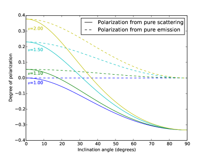
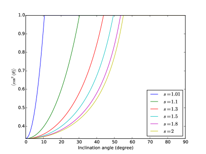
We follow Kataoka et al. (2015a) in adopting the grain model of Pollack et al. (1994), where grains are composed of silicate (8% in volume), water ice (62%) and organics (30%). This type of dust grains has a complex dielectric constant of (where is the imaginary unit ) at mm. In Fig. 1, we plot the degree of polarization for scattered light and direction emission, and , for several representative values of the axis ratio of the oblate grain, , , and , as a function of the disk inclination angle . Several features are immediately apparent. First, in the limit of spherical grains with , we recover the well known (analytic) results that the direct emission is not polarized, and the polarization from scattering is along the minor axis, with a polarization fraction that goes from zero to as the inclination angle increases from to . Second, as anticipated analytically in the last subsection, the polarization of the light scattered by the oblate grains aligned with a toroidal magnetic field (along the -direction) is along the -axis (with a positive ) in the face-on case. As the inclination angle increases, the polarization along the major (or -) axis is gradually weakened by that from the polarization induced by the inclination, which is along the minor (or -) axis. At a critical inclination angle , the polarization direction switches from the major axis to the minor axis; the angle increases with the axis ratio . In all cases, the scattering degree of polarization asymptotes to the limiting value as the inclination angle approaches , as we showed analytically above. Third, the polarization of the direct emission by the aligned oblate grains is always along the major (or -) axis of the disk, which is the direction of the long axis of the grain. The polarization degree peaks in the face-on case, where the grain appears most elongated to the observer. Interestingly, the peak value is exactly the same as that of the scattering polarization degree in the face-on case, which can be proven analytically for oblate grains. Lastly, the emission polarization degree decreases smoothly with the inclination angle , reaching zero in the edge-on limit, when the oblate grains appear circular to the observer and thus there is no preferred direction for polarization. The vanishing of as means that the polarization will be dominated sooner or later by scattering, as long as the inclination angle is large enough.
The relative contribution of scattering and direct emission to the polarization depends on not only the degree of polarization ( and ), but also the ratio of and , where is mean intensity at the location under consideration, is the local source function for thermal dust emission, and and are the scattering and absorption cross sections. The ratio depends on the detailed disk model and temperature structure, while the ratio of scattering and absorption cross sections, , depends on the dust composition and especially grain size. Roughly speaking, the cross section ratio is of the order . In order for the scattering to be competitive, the grain size cannot be much smaller than the wavelength . On the other hand, the electrostatic approximation that we adopted is valid only when the grain is relatively small compared to the wavelength. As we show in § 5 below, the scattering opacity exceeds the absorption opacity as long as the grains are bigger than , while the electrostatic approximation remains valid for grain sizes up to . For larger grains, the scattering opacity remains larger than the absorption opacity, but their optical properties need to be computed numerically; we postpone such a treatment to a future investigation. In what follows, we will leave the ratio as a free parameter, and explore the parameter space where the polarization from scattering becomes important relative to that from direction emission.
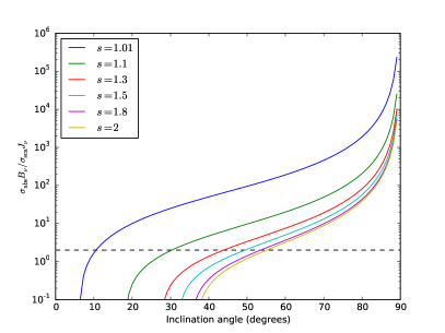
Since the polarization from direct emission at a location on the major axis is always along the major axis (for a purely toroidal magnetic field), one way to measure the importance of the scattering is to determine the transition inclination angle beyond which the polarization is forced to align with the minor axis instead. In Fig. 2, we plot the angle as a function of the ratio for a representative set of values for the axis ratio . Roughly speaking, for each value of , the polarization is dominated by direct emission in the parameter space to the upper left of the corresponding curve, and by scattering to the lower right of the curve. Also shown in the plot is the fiducial value of derived in the flared disk model of Cho & Lazarian (2007). For this fiducial value, the polarization is dominated by scattering for greater than approximately as long as the grain axis ratio is not too extreme (, see Hildebrand & Dragovan 1995). For larger ratios of , a more extreme inclination is required for the scattering to become dominant, unless the grains are nearly spherical (i.e., with close to 1). In what follows, we will evaluate this ratio self-consistently with the help of a specific disk model. The effects of two potential complications, imperfect grain alignment and non-oblate grain shape, are discussed in the Appendix A.
3 Competition between scattering and direct emission in young star disks: numerical examples
So far, we have limited our (analytic) discussion of the interplay between the polarizations produced by non-spherical grains through scattering and direct emission to the limiting case where the incident radiation field is both planar and isotropic in the disk plane. While the planar approximation is usually a good one, especially for large grains that tend to settle to the disk mid-plane, the isotropic assumption is adopted mainly for the purposes of illustrating the competition between scattering and emission as simply as possible. In this section, we will relax this assumption with the help of a specific model for the disk structure, which enables a self-consistent computation of the angular distribution of the incident radiation field, as done in Paper I. More importantly, the disk model allows for a determination of the polarization pattern over the entire disk, which is needed for direct comparison with spatially resolved polarization observations, especially those with ALMA. We will keep the “thin-disk” approximation adopted in Paper I, which has been shown to greatly speed up the computation of the scattering-induced polarization in an inclined disk by spherical grains without compromising the essential physics of the problem. Our treatment here is essentially a generalization of Paper I to the case of non-spherical grains, where both scattering and direct emission contribute to the polarization. It turns out that the combined polarization pattern resembles that observed recently in NGC1333 IRAS4A with VLA at 8 mm and 1 cm (Cox et al., 2015). The application of our results to this specific source will be discussed in § 4.
3.1 Problem setup
We will compute the polarizations due to the direct thermal emission and scattering by non-spherical grains separately. The former can be done through straightforward integration along each line of sight once the grain properties, magnetic field configuration, and degree of grain alignment are specified. The latter is more complicated because, along each line of sight, it involves the computation of the incident radiation field to be scattered at all locations and the integration of the scattered light. To treat the scattering-induced polarization, we will adopt the same basic problem setup as in Paper I (see § 2.1 there for details). Particularly important for their formulation of the scattering problem is the assumption that the disk is both geometrically and optically thin. This simplification enabled us to relate the source function of the radiation scattered into the line of sight at any target location on the (thin, inclined) disk to the column density and temperature at a source location (which supplies the photons to be scattered at ), and , through their equations (6)-(7), which are reproduced here for easy reference:
| (10) |
where is the frequency of the scattered light, is the Boltzmann constant, the absorption opacity, the speed of light, the solid angle-integrated (total) scattering cross section, the differential scattering cross section, and the quantity is an integral along a straight line on the disk that passes through the target location along a constant azimuthal angle :
| (11) |
where is the local disk scale-height at and is the separation between the target and source locations, and .
In the simpler case of (small) spherical grains considered previously in Paper I, the differential scattering cross section in equation (10) is simply given by Rayleigh scattering. For non-spherical grains, there are two potential complications. The first is that the incident radiation to be scattered at a given location is already polarized before scattering because it is emitted by non-spherical grains. In principle, one needs to determine the polarization state of the incident radiation carefully, taking into account of the grain orientation at each source location along the line of integration in equation (11). For simplicity, we shall assume that the incident light is unpolarized before scattering. This approximation should not change the polarization produced by scattering qualitatively, as explained in the Appendix B.
The second complication is that, for non-spherical grains, the scattering matrix (see equations 4 and 5), which determines the differential cross section in equation (10), will depend on two angles, the incident radiation direction and line of sight direction in the frame of the dust grains, rather than a single scattering angle, as it is in Rayleigh scattering. These matrix elements can be computed easily once the grain properties and degree of grain alignment are specified. For illustrative purposes, we will adopt the same grain model of Kataoka et al. (2015a) used in the last section (§ 2) and assume that the grains are oblate spheroids perfectly aligned with a purely toroidal magnetic field in the disk; grains of other shapes (e.g., prolate) and/or imperfectly aligned should produce qualitatively similar results after averaging around the field direction (see Appendix A). We adopt a volume-equivalent radius m to maximize the effects of the scattering of radiation at 1 mm wavelength and a rather large axis ratio of , so that the direct emission is significantly polarized. Other choices of and would not change the polarization patterns produced by scattering and direct emission individually, but will affect their relative importance in a simple way: increasing () tends to make scattering (direct emission) more important.
3.2 Numerical examples of disk polarization pattern from both scattering and emission
For our numerical examples, we adopt the column density distribution of the viscous disk model of Pringle (1981):
| (12) |
which is often used for modeling disk continuum observations (e.g., Testi et al., 2014; Kwon et al., 2015). The prescribed disk profile has an inner part with a power-law distribution and an outer part dominated by an exponential cutoff. Most observed disks have an inferred value of the power index between and (Andrews et al., 2009; Segura-Cox et al., 2016). We have experimented with different values of in this range and found similar polarization patterns. Only the results for the case will be shown below.
The size of the model disk is set by the characteristic radius . It provides an overall scaling for the polarization pattern, but does not change the pattern itself. For definitiveness, we choose AU, and truncate the disk beyond an outer radius AU. The inner radius of the disk is set to AU in order to prevent the column density from going to infinity at the origin. For the temperature profile, we adopt the simple prescription
| (13) |
which is approximately valid for disks heated by the central stellar radiation (e.g., Hartmann et al., 1998). We will assume the radiation is in the Rayleigh-Jeans regime and all the intensities will be presented in unit of the Planck function ; the dimensionless intensities are independent of . As a concrete illustrative example, we set the scale factor for the total (gas and dust) column density to (with a gas-to-dust-ratio of 100), so as to prevent the optical depth for direct emission from becoming too large, especially at small radii, on the one hand and to make the optical depth for scattering large enough that the scattering can compete with direct emission in producing polarization on the other. The key parameter that we will focus on is the inclination angle , which is expected to change the balance between the polarization produced by scattering and that by direct emission, based on the analytic results described in § 2.
We will start with the simplest, face-on case (), which is free of any disk inclination effect. In this case, the polarization pattern for the direct emission from the oblate grains that are perfectly aligned with a purely toroidal magnetic field is trivial: the polarization direction is radial everywhere (see upper-middle panel of Fig. 3). The pattern for the scattered light is more structured. The polarization direction is radial inside a radius of AU (this radius depends on the disk mass and temperature distributions), and becomes azimuthal outside (see upper-left panel). This is very different from the pattern in the case of spherical grains (see the top-left panel of Fig. 2 of Paper I), where the polarization direction is azimuthal everywhere, including at small radii, where the polarization fraction is small, because the incident radiation field at these radii is more or less isotropic in the disk plane. In contrast, for non-spherical grains, the scattered light can be significantly polarized even for (planar) isotropic incident radiation, as we demonstrated analytically in the last section (see Fig. 1). Since the oblate grains are aligned with their shortest axes along the azimuthal (B-field) direction, incident light coming from the radial direction (with an electric field along the azimuthal direction) is scattered less efficiently than that from the azimuthal direction (with along the radial direction), leading to polarization along the radial direction at small radii where the incident radiation field in the disk plane is more or less isotropic. As the radius increases, the incident radiation field becomes more beamed in the radial direction, which leads to the polarization along the azimuthal direction in the outer part of the disk. Indeed, the incident radiation near the outer edge of the disk shown in Fig. 3 is so beamed in the radial direction that the polarization fraction iof the scattered light s more than 50%.
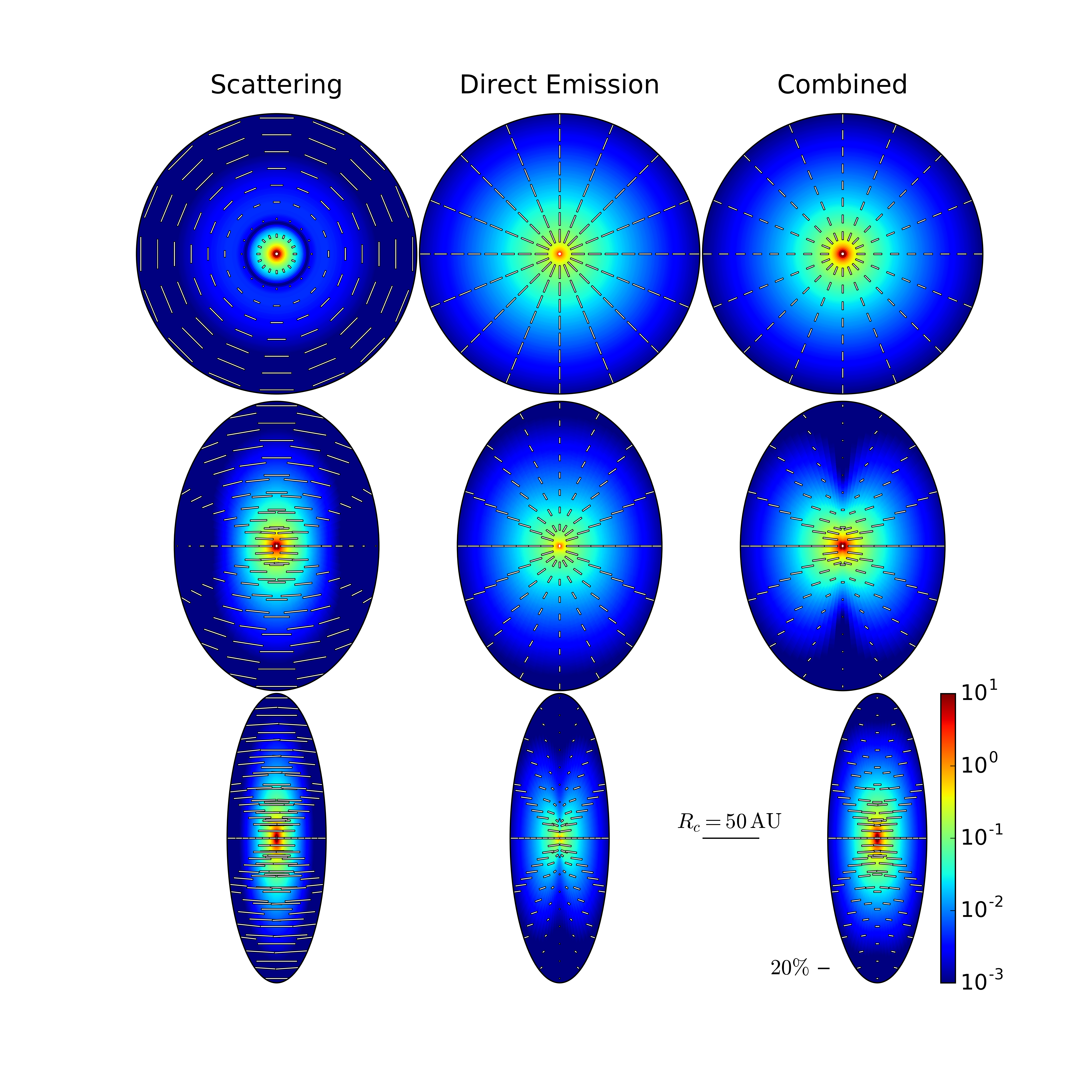
Despite the high polarization fraction, the polarized intensity of the scattered light is relatively low in the outer part in this particular example, so that the polarization of the combined light from both direct emission and scattering is in the radial direction everywhere (see the upper right panel). The radial polarization pattern does not mean that the direct emission dominates the polarization everywhere. Indeed, close to the center, the polarization is dominated by scattering333The exact size of the scattering dominated central region depends on the disk structure and dust properties, and will require more elaborate models to determine if the region becomes optically thick.. This illustrates the potential danger of automatically identifying radial polarization with the direct emission from grains aligned with a toroidal magnetic field in a face-on disk. Other pieces of information, such as grain properties and disk radiation field, are needed to help determine unambiguously which polarization mechanism dominates.
As the angle increases, the inclination-induced polarization in the scattered light becomes more important, which reduces the difference between the spherical and non-spherical grain cases (compare the lower-left panel of Fig. 2 of Paper I with the middle-left panel of Fig. 3 for the case). In particular, in the inner part of the disk where the incident radiation field in the disk plane is not far from being isotropic, the scattered light is polarized more or less along the minor axis of the disk, which is the hallmark of the inclination-induced polarization; it is very different from the radial pattern seen in the face-on case (see the upper-left panel). In addition, both the ring of null polarization and the azimuthal polarization pattern in the outer part of the disk of the face-on case disappear, again because of the inclination-induced polarization.
As emphasized in Paper I for spherical grains, the tendency for the inclination-induced polarization in the scattered light to lie along the minor axis is a simple consequence of the (thin) disk geometry and maximum polarization at scattering angle for small grains. For locations on the major axis of a disk of inclination angle , the incident radiation coming from the radial direction is scattered by into the line of sight, whereas that from the locally azimuthal direction (i.e., perpendicular to the local radial direction in the disk plane) is scattered by or . This difference in scattering angle makes the polarization from the former, which is along the minor axis, more important relative to that from the latter. Similarly, for locations along the minor axis, the incident light along the locally azimuthal direction is scattered by , and that along the radial direction (in the disk plane) by or . The difference increases the relative importance of the polarization from the former, which is again along the minor axis. This basic picture is qualitatively similar for both spherical and non-spherical grains.
The polarization produced by direct emission is also affected by the disk inclination. Although the polarization vectors remain perpendicular to the local toroidal magnetic field projected onto the plane of the sky (see the middle-middle panel for the case), the polarization fraction is changed significantly by the inclination, especially at locations on the major axis, where it is reduced compared to the face-on case, by a factor of about 2 for for the particular grain model with adopted here (see Fig. 1). As mentioned earlier, for locations on the minor axis, the aligned oblate grains appear “edge-on” to the observer independent of the inclination angle, and their polarization fraction remains unchanged. Therefore, a generic feature of the polarization produced by the direct thermal emission of magnetically aligned oblate (or effectively “oblate”, see Appendix A for a discussion) grains is that, as the inclination angle increases, the distribution of the polarization fraction becomes more non-uniform azimuthally, with the radiation on the minor axis becoming increasingly more polarized compared to that on the major axis. The degree of the contrast between the two axes depends sensitively on the grain axis ratio , which is unfortunately uncertain in general.
The inclination-induced contrast between the polarizations produced by the direct emission on the major and minor axes is further increased when the scattering is also included (see the middle-right panel). The main reason is that, for our particular grain model, the polarizations produced by direct emission and scattering are in orthogonal directions at locations on the major axis (see the middle-left and middle-middle panels, see Fig. 1). It leads to a null point at a radius AU on the major axis where the polarization from the scattering cancels that from the direct emission exactly. Closer to the center, the polarization is dominated by the scattering (which produces a higher polarized intensity in this particular example), with a direction along the minor axis; the opposite is true beyond the null point (although this is hard to see clearly in the middle-right panel because of low polarization fraction). In contrast, at locations on the minor axis, the polarizations from both direct emission and scattering are along the same direction; they add to, rather than cancel, each other. The net result is a “butterfly-shaped” pattern for the polarized intensity.
Besides the strong azimuthal variation in the polarization fraction, there is also a significant radial dependence in the direction of the combined polarization. At relatively small radii (within AU), the polarization is dominated by scattering with direction more or less along the minor axis. At larger radii, the direct emission becomes more important, turning the polarization morphology into a more fan-like pattern. This example illustrates the potential richness of the interplay between the polarizations produced by scattering and direct emission in an inclined disk, even though the underlying magnetic field is simple (purely toroidal): the combined polarization varies both radially and azimuthally and in both direction and polarization fraction. In particular, it includes a polarization “hole,” where the polarizations from the two competing mechanisms cancel each other. We should stress that, for this intriguing composite pattern to appear, the polarized intensities from the direct emission and scattering must be comparable. Whether it can happen naturally is uncertain. In the discussion section, we will return to this and other issues, including the fact that the patterns of the polarization vectors appear very different in the scattering and emission cases for this intermediate inclination , which should be distinguished observationally.
In the lower panels of Fig. 3, we show the case of an even more inclined disk, with . Not surprisingly, the inclination effect becomes more prominent for the polarizations produced by both scattering and direction emission. Specifically, the polarization from scattering has a direction nearly parallel to the minor axis everywhere, and a polarization fraction close to the maximum value of (see the lower-left panel). This pattern is similar to the highly inclined case with spherical grains, indicating that the effect of grain non-sphericity is largely masked by that of inclination. For the direct emission, the polarization near the major axis is greatly reduced relative to that near the minor axis (the lower-middle panel), producing a much more pronounced “butterfly” pattern than the case (the middle-middle panel). The patterns of the polarized intensity are so distinct in the scattering and emission cases that one should be able to tell them apart observationally in principle. In practice, the characteristic “butterfly” pattern would be smeared out in disks with large inclination angles such as unless the distribution of the polarized intensity along the minor axis is well resolved spatially. Such well resolved observations should also be able to reveal the difference in the polarization direction and thus help distinguish the two cases.
The total polarization pattern for the highly inclined case including both emission and scattering is shown in the lower-right pattern. It appears very different from that of the intermediate inclination () case (the middle-right panel). In the case, the “butterfly” pattern in the polarized intensity is barely recognizable for the emission only case, but becomes much more prominent in the combined case, because the polarization produced by the emission along the major axis is largely canceled out by that produced by the scattering. In contrast, in the case, the “butterfly” pattern is much more prominent for the emission only case, but completely disappears in the combined case, because the low polarized intensity region along the major axis (the gap between the two “wings of the butterfly”) is filled in by the scattering-produced polarization. In any case, the systematic change in polarization pattern from to to is driven mainly by the expected decrease of the polarization from emission along the major axis and the increase of that from scattering at the same time.
4 The Case of NGC1333 IRAS4A1
IRAS4A is a well studied protobinary system in the NGC1333 region of the Perseus molecular clouds. It is the first protostellar system where a dust polarization pattern corresponding to an “hourglass-shaped” magnetic field is detected on the 1000-AU, inner protostellar envelope (Girart et al., 2006). Given the relatively large scale (and the relatively low corresponding volume and column densities), it is unlikely for the scattering to dominate the observed polarization; the required grain size and column density are too large for the envelope. On this scale, the conventional interpretation involving direct emission by non-spherical grains aligned with respect to a (pinched) magnetic field appears secure.
On the smaller scale of 100 AU, Cox et al. (2015) recently detected polarization at 8.1 and 10.3 mm with VLA for the brighter component, A1, of the protobinary system. The polarization at 8.1 mm, which is significant for more independent beams than that at 10.3 mm, is reproduced in Fig. 4 for easy reference.
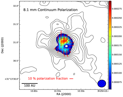
As stressed by Cox et al., the polarization pattern on the 100 AU scale appears very different from that on the 1000-AU scale. It broadly resembles the pattern expected from direct emission by grains aligned with respect to a toroidal magnetic field in a face-on disk. It is unclear, however, whether a sizable rotationally supported disk exists in this source. The VLA continuum images appear marginally resolved, which may be indicative of a disk not much smaller than the resolution limit ( AU). There is, however, little kinematic data on this scale to confirm or reject the possibility of a Keplerian rotation. If the disk is indeed nearly face-on, the disk rotation would be difficult to measure directly. However, the red- and blue-shifted lobes of its bipolar molecular outflows are cleanly separated spatially on the few 100 to few 1000 AU scale (Santangelo et al., 2015; Ching et al., 2016), indicating that the outflows are not exactly along the line of sight and, by implication, the disk is unlikely viewed face-on. If this interpretation is correct, the roughly north-south orientation of the molecular outflows would imply a disk major axis along approximately the east-west direction.
Additional support for an inclined disk comes from modeling of the 8 mm dust continuum emission, which is consistent with an inclination angle of . Further evidence for significant inclination may come from the detected polarization pattern itself. The polarization fraction is significantly smaller along the east-west direction than along the north-south direction; such a contrast is not expected in a face-on disk (see the upper panels of Fig. 3). It is, however, qualitatively consistent with the polarization pattern produced by direct emission from an inclined disk with the major axis along the east-west direction, as indicated by the molecular outflow orientation. As stressed earlier and illustrated in Fig. 3, the polarization fraction is reduced along the major axis relative to that along the minor axis by disk inclination. The magnitude of the contrast, denoted by , increases with the inclination angle , and has a weak dependence on the degree of grain non-sphericity (characterized in our model by the grain axis ratio ), as illustrated in Fig. 5. It is easy to show, from Equation 9, that the contrast is given analytically
| (14) |
in the limit (i.e., as the oblate spheroid approaches a sphere, with ). The above expression provides a good estimate for for the range of (between 1 and 2) shown in Fig. 5.
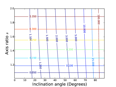
Also plotted in the figure are lines of constant maximum polarization fraction . This maximum value depends on the grain axis ratio but not the inclination angle, and is reached at locations along the minor axis (i.e., ). This diagram can help evaluate whether the polarization observed in a particular source comes from direct emission or not.
In the case of IRAS4A1, the polarization fraction is the highest along the minor axis in the north-south direction (see Fig. 4), consistent with the direct emission interpretation. The maximum value in the north is , which is somewhat larger than that in the south (). In the grain model adopted in this paper, these degrees of polarization correspond to a grain axis ratio of and respectively in this interpretation. The upper limit on the inclination angle was set by fitting the 8 mm continuum data to a disk model in the uv-plane, following the method used in Segura-Cox et al. (2016). The shortest baselines ( 350 k) were omitted from the data to better exclude envelope emission for the modeling. Since the inclination angle is likely less than degrees based on the continuum modeling444Ching et al. (2016) suggested a larger inclination angle of based on outflow modeling, although the inferred angle depends strongly on their model assumptions. If the inclination is indeed this high, the scattering would be more important relative to direct emission., the contrast should be less than . This expectation is confirmed in the left panel of Fig. 6, where we show the polarization pattern at 8 mm from emission by perfectly aligned oblate grains of 0.6 mm in size and in axis ratio (adopting the same grain material as in § 3, which has a complex dielectric constant at 8 mm). The inclination angle was set to , which is on the high side of the range preferred by the continuum modeling. As expected, there is some contrast between the minor and major axes in the polarization fraction (and polarized intensity). The contrast appears less than that suggested by observation: roughly 12-18% along the (minor) north-south axis and approximately 3-4% along east-west. That is, the contrast is at least a factor of 3, and likely significantly higher. In order to produce such a high contrast, a disk inclination angle of or more is needed according to Equation (14). Such a large inclination, although cannot be ruled out completely, is unlikely based on the continuum modeling.
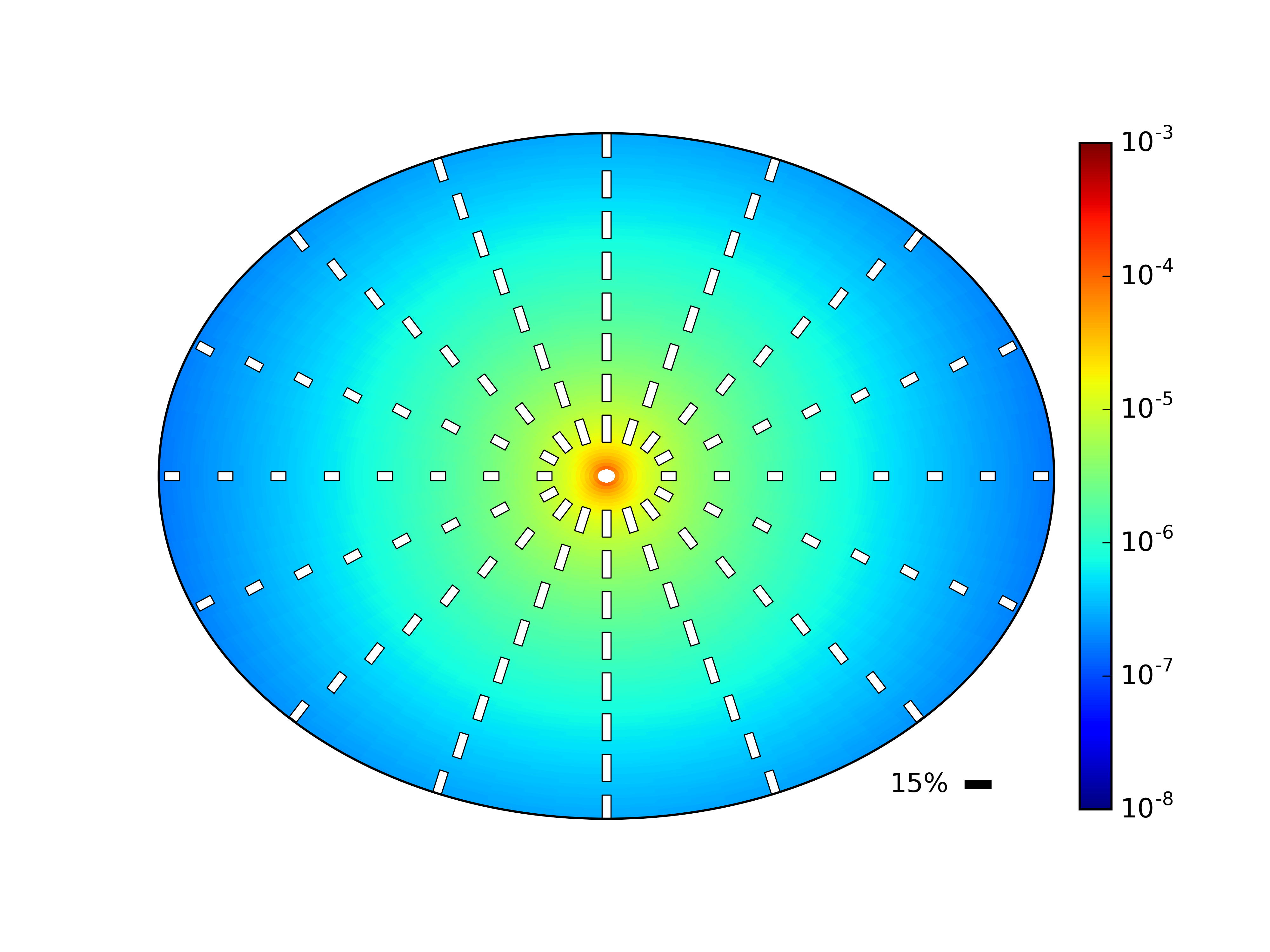
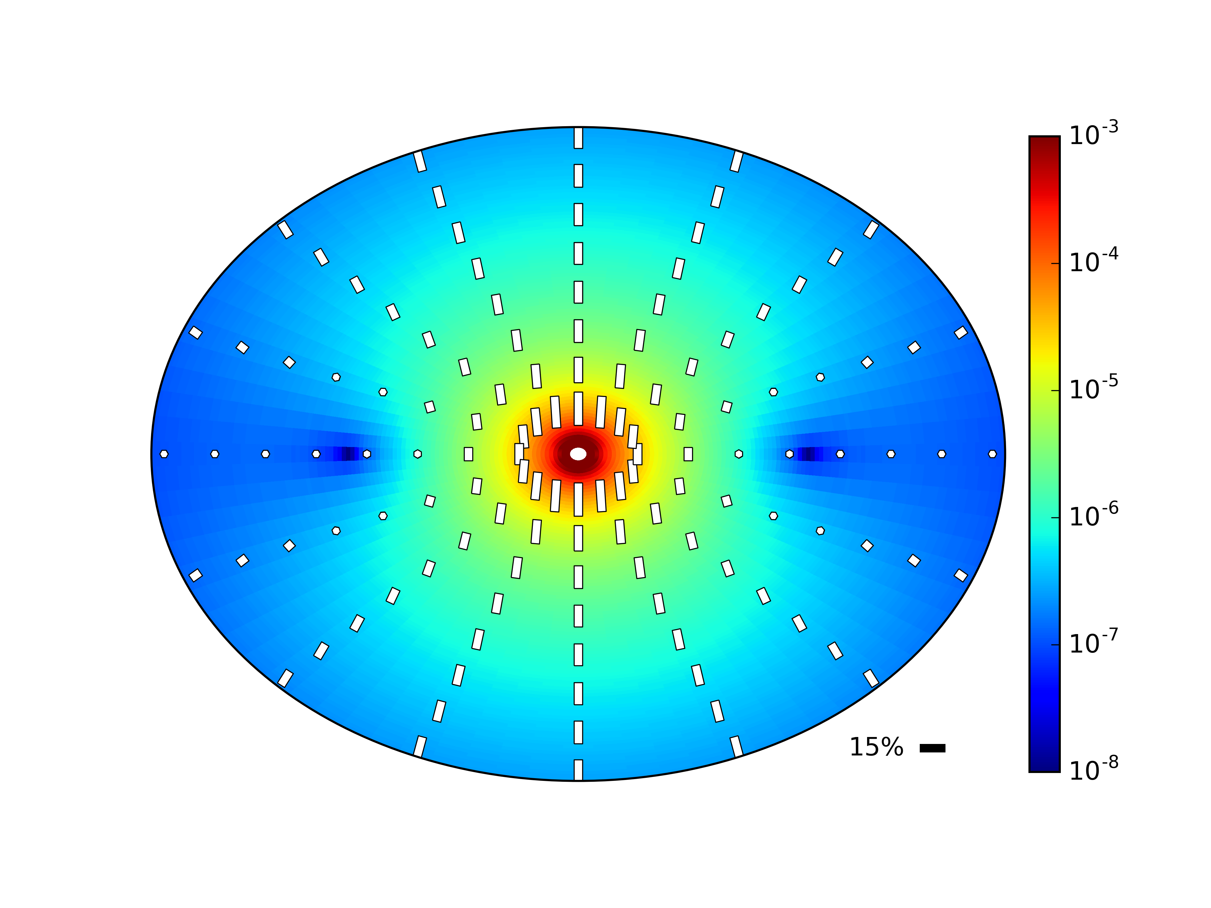
Another, perhaps more severe, drawback of the emission only model is that it predicts a purely east-west orientation for the polarization vectors on the major axis, which matches the observed vectors near the western edge but not those closer to the center, which are oriented more or less north-south (i.e., along the minor axis). The orientations of these central vectors can naturally arise from scattering, which has the added advantage of canceling out some of the polarization produced by emission on the major axis and thus bringing the contrast closer to the observed level. This is illustrated in the right panel of Fig. 6, where we include the contributions to the polarization from both emission and scattering. In this particular example, the scattering dominates the emission near the center and visa versa near the edge. Two polarization “holes” are produced at a distance of AU along the major axis, one on each side of the origin. They broadly resemble the polarization “hole” to the west of the center555We checked that the polarization “hole” is not where the emission at longer wavelengths (1 and 4 cm) peaks, and is therefore unlikely caused by unpolarized free-free emission. and, to a lesser extent, the low-polarization “bay” to the east. The inclusion of scattering appears to have improved the agreement between the model and observations significantly, at least in some broad features.
The inclusion of scattering does not improve the agreement in other observed features, however. For example, the north-south asymmetry in the polarized intensity (see Fig. 4) cannot be accounted for in our simple semi-analytic model that assumes an axisymmetric disk structure. Asymmetry in the disk properties, such as the dust distribution, could be a culprit. Another discrepancy is that the polarized intensity is peaked at the center in the model but not in the observed map. However, the central region may be optically thick, which would reduce the polarization fraction for both the directly emitted and scattered light (Liu et al. 2016). In any case, more detailed models will be needed to explain these features, especially when they become better quantified with higher resolution and sensitivity observations in the future.
5 Implications and Future Refinements
We have found suggestive evidence that the dust scattering may have contributed significantly to the polarization observed in NGC1333 IRAS4A1 on the 50 AU scale, especially in the central region and along the major axis. However, the concentration of the polarized light along the minor axis and the “fanning out” of most of the polarization vectors point to a polarization pattern dominated by the direct emission from grains aligned with respect to a toroidal magnetic field as the dominant mechanism, especially in the outer regions, with the strong implication that the disk is indeed magnetized. This is very different from the case of HL Tau disk, where the polarized light is concentrated along the major axis, and all polarization vectors are more or less parallel to the minor axis (Stephens et al., 2014). As emphasized in Paper I (see also Kataoka et al. 2015b), these features are explained more naturally by dust scattering than direct emission. These two examples illustrate the diversity of the polarization pattern on the disk scale and the need to include both scattering and direct emission for interpreting the observations. The need will only increase in the near future as ALMA disk polarization observations with higher spatial resolution and sensitivity become available.
There are several factors that determine the relative importance of the scattering and emission in disk polarization, including the grain properties, disk structure and inclination. A key factor is the grain size, to which the scattering opacity is highly sensitive. This sensitivity is illustrated in Fig. 7, where we plot the scattering and absorption opacities as a function of the grain size for oblate grains with an axis ratio , obtained using both the electrostatic approximation and discrete dipole approximation (Draine & Flatau, 1994, DDSCAT) at wavelength mm. Also plotted for comparison is the opacity for spherical grains of the same size computed from the Mie theory. As mentioned earlier, the scattering opacity for grains smaller than about . It starts to exceed the absorption opacity only for grains larger than . The sensitive dependence of on is a double-edged sword. It implies a relatively narrow range in grain size, from to , for the scattering to be competitive with direct emission and the electrostatic approximation adopted in this paper to hold666Note that the grain sizes used in § 3 and § 4 are in this range, so our treatment is self-consistent.. Scattering may still dominate direct emission for grains above this size range, but its polarization patterns will likely be quite different from those discussed in this paper (including, e.g., polarization reversal, Paper I) and will need more elaborated methods, such as the Discrete Dipole Approximation (e.g., Draine & Flatau, 1994), to determine; we will postpone such a treatment to a future investigation.
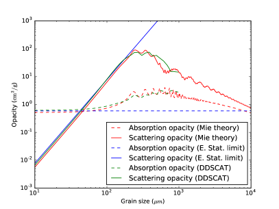
On the other hand, if the polarization pattern observed in a disk requires dust scattering to explain, the size of the scattering grains must lie in a relatively narrow range. The case of IRAS4A1 is particularly interesting in this context. To produce significant polarization at 8 mm by dust scattering, the grains must be roughly millimeter-sized (or larger). In this source, there is evidence for polarization from direct emission as well. If the polarized emission is dominated by the same grains that are responsible for the scattering, it would imply that large, millimeter-sized, grains can indeed be aligned with respect to the magnetic field inside the disk. This inference is important because, compared to the micron-sized (or smaller) grains that are more commonly discussed in the grain-alignment literature, the much larger, millimeter-sized, grains are more difficult to align by radiative torque because of their slower internal relaxation (Hoang & Lazarian, 2009) and slower Lamor precession around the field (Lazarian, 2007). The latter obstacle can in principle be overcome with a strong enough magnetic field. Therefore, alignment of large grains can potentially provide an indirect estimate of the lower limit to the field strength that is all-important to the disk dynamics; we will postpone the quantification of this limit to a future investigation.
A potential complication is that the grains responsible for the scattering and direct emission may not have the same sizes. For example, in the case of IRAS4A1, the central part of the disk where scattering appears to dominate the polarization may have large grains while the direct emission-dominated outer part could have smaller grains. Indeed, there is evidence for such a spatial gradient, with the grain size increasing toward the center, from the distribution of opacity spectral index in a number of (relatively evolved) disks (e.g., Pérez et al., 2012; Testi et al., 2014; Guidi et al., 2016). The gradient is also expected on theoretical grounds (e.g., Birnstiel et al., 2012). The inward increase in grain size tends to make the scattering-induced polarization more important at smaller radii (in addition to a higher column density there), as appears to be the case in IRAS 4A, although the optical depth close to the center could be substantial, which may invalidate the optical thin approximation and single scattering assumption adopted in the paper. These effects should be treated self-consistently in more refined models in the future, together with the expected spatial variation of grain properties. Another refinement is to include the polarization of the incident light in treating the scattering.
If the observed polarization is dominated by direct emission from magnetically aligned grains, the polarization fraction may provide a handle on the grain shape. For perfectly aligned oblate spheroids, there is a one-to-one relation between the grain axis ratio and the maximum polarization fraction (see Fig. 5). For example, values of and would imply axis ratios of and , respectively. However, the polarization could also be produced by prolate grains, whose optical properties are similar to those of the oblate grains when averaged around the magnetic field direction (see Appendix A). Furthermore, alignment with the magnetic field may not be perfect, especially for large grains with Larmor precession time scales longer than the disk lifetime. For imperfectly aligned grains, larger deviation from spherical shape is needed to produce the same degree of polarization. Therefore, there is a degeneracy between different grain shapes (oblate vs prolate) and between the grain shapes and their degrees of alignment that is difficult to break with the observed polarization fraction alone. Grain growth models and detailed grain alignment calculations, together with higher resolution and sensitivity data, may be needed to break the degeneracy.
6 Conclusion
Using the electrostatic approximation, we have taken a first step toward developing a general theory for disk polarization in millimeter and centimeter that includes both direct emission from magnetically aligned, non-spherical grains and scattering by the same grains, with an emphasis on the relative importance of these two mechanisms and how they are affected by disk inclination. We have adopted the approximation of unpolarized incident light for scattering, which could affect the polarization produced by scattering at a level up to a few tens of percent (see Appendix B). With this caveat in mind, the main results are as follows:
1. The polarizations produced by scattering and direct emission both depend strongly on the disk inclination, which changes the relative importance of the two, especially along the (projected) disk major axis in the plane of the sky. This change was illustrated analytically with a simple case where oblate grains are perfectly aligned with a purely toroidal magnetic field at a location on the major axis where the incident radiation field is assumed isotropic (see Fig. 1). For a nearly face-on disk, both scattering and direct emission produce polarization along the major axis (or radial direction) at the location; they tend to reinforce each other. As the inclination angle increases, the direction of the scattering-induced polarization switches to the minor axis, with the polarization fraction increasing to as . In contrast, the polarization produced by direct emission remains along the major axis, with the polarization fraction decreasing monotonically to zero as . Therefore, for large disk inclinations, the polarizations from scattering and direct emission tend to cancel each other on the major axis, with the scattering dominating the direct emission in the limit of edge-on disks. For less extreme disk inclinations, the relative importance of the two competing mechanisms depends on the properties of the dust grains, especially their size and degree of non-sphericity, and the ratio of the Planck function for thermal dust emission and the mean intensity of the incident radiation field to be scattered by the grains.
2. The scattering and direct emission by magnetically aligned, non-spherical grains produce polarization patterns that should be easily distinguishable in general but not always. This was illustrated with a geometrically and optically thin dust disk of a prescribed column density and temperature distribution and a purely toroidal magnetic field (see Fig. 3). For significantly inclined disks, the difference between the two mechanisms is most pronounced at locations on the major axis, where the polarized intensity is enhanced relative to that on the minor axis and the polarization direction is along the minor axis for scattering while the opposite is true for direct emission. For nearly face-on disks, the direction of the scattering-induced polarization near the disk center where the radiation field is more or less isotropic in the disk plane is the same as that from direct emission, making it hard to distinguish the two (both radial). At larger radii where the radiation field in the disk plane is more radially beamed, the scattering-induced polarization switches to the azimuthal direction, which is orthogonal to that from the emission. The interplay between these two competing mechanisms can yield interesting new polarization patterns, especially when their polarized intensities are comparable. Particularly intriguing is the pattern produced in a disk of intermediate inclination with the scattering dominating the inner region of the disk and the emission the outer: the polarization directions are nearly uniform (along the minor axis) at small radii, and become increasingly radial at larger distances, with two “null” points located on the major axis (one on each side of the origin) where the polarizations from scattering and direct emission cancel out exactly. The “null” points serve as a signpost for both mechanisms contributing significantly to the polarization.
3. There is suggestive evidence that the polarization pattern observed in NGC1333 IRAS4A1 at 8 mm is shaped by a combination of direct emission and scattering. The scattering and direct emission naturally account for, respectively, the relatively uniform polarization directions observed in the central region and the roughly radial pattern at larger distances (see Fig. 4). Most interestingly, there is clear evidence for at least one “null” point in the observed polarization map, which can naturally be interpreted as the location on the major axis of an inclined disk where the polarizations from the scattering and direct emission cancel each other. The implied disk orientation matches that required for launching the observed molecular outflows.
4. If both direct emission and scattering from the same magnetically aligned grains indeed contribute significantly to the polarization observed in IRAS 4A1, it would imply not only that a magnetic field exists on the disk scale, but that it is strong enough to align large, possibly millimeter-sized, grains, at least in this source, with potentially far reaching consequences for the disk dynamics and evolution. This inference remains tentative, however, in this early stage of observations and modeling of disk polarization. The situation should be greatly improved in the near future with the higher resolution and sensitivity ALMA observations and model refinements.
We thank Chat Hull and an anonymous referee for helpful comments. ZYL and HFY are supported in part by NASA NNX14AB38G and NSF AST-1313083.
References
- Andersson et al. (2015) Andersson, B.-G., Lazarian, A., & Vaillancourt, J. E. 2015, ARA&A, 53, 501
- Andrews et al. (2009) Andrews, S. M., Wilner, D. J., Hughes, A. M., et al. 2009, ApJ, 700, 1502
- Armitage (2015) Armitage, P. J. 2015, preprint (arXiv:1509.06382)
- Balbus & Hawley (1991) Balbus, S. A., & Hawley, J. F. 1991, ApJ, 376, 214
- Birnstiel et al. (2012) Birnstiel, T., Klahr, H., & Ercolano, B. 2012, A&A, 539, A148
- Blandford & Payne (1982) Blandford, R. D., & Payne, D. G. 1982, MNRAS, 199, 883
- Bohren & Huffman (1983) Bohren, C. F. & Huffman, D. R. 1983, Absorption and scattering of light by small particles. Wiley New York NY
- Ching et al. (2016) Ching, T.-C., Lai, S.-P., Zhang, Q., et al. 2016, preprint (arXiv:1601.05229)
- Cho & Lazarian (2007) Cho, J. & Lazarian, A. 2007, ApJ, 669, 1085
- Cox et al. (2015) Cox, E. G., Harris, R. J., Looney, L. W., et al. 2015, ApJ, 814, L28
- Draine & Flatau (1994) Draine, B. T., & Flatau, P. J. 1994, Journal of the Optical Society of America A: Optics and Image Science, 11, 1491
- Girart et al. (2006) Girart, J. M., Rao, R., & Marrone, D. P. 2006, Science, 313, 812
- Guidi et al. (2016) Guidi, G., Tazzari, M., Testi, L., et al. 2016, preprint (arXiv:1601.07542)
- Hartmann et al. (1998) Hartmann, L., Calvet, N., Gullbring, et al. 1998, ApJ, 495, 385
- Hildebrand & Dragovan (1995) Hildebrand, R. H., & Dragovan, M. 1995, ApJ, 450, 663
- Hoang & Lazarian (2009) Hoang, T., & Lazarian, A. 2009, ApJ, 697, 1316
- Hoang & Lazarian (2012) Hoang, T., Lazarian, A. 2012, Advances in Astronomy, 2012, Article ID 208159
- Hughes et al. (2009) Hughes, A. M., Wilner, D. J., Cho, J., et al. 2009, ApJ, 704, 1204
- Hughes et al. (2013) Hughes, A. M., Hull, C. L. H., Wilner, D. J., et al., ApJ, 145, 115
- Kataoka et al. (2015a) Kataoka, A., Muto, T., Momose, M., et al. 2015a, ApJ, 809, 78
- Kataoka et al. (2015b) Kataoka, A., Muto, T., Momose, M., et al. 2015b, preprint (arXiv:1507.08902)
- Kwon et al. (2015) Kwon, W., Looney, L. W., Mundy, L. G. & Welch, W. J. 2015, 808, 102
- Lazarian (2007) Lazarian, A. 2007, J. Quant. Spectrosc. Radiative Transfer, 106, 225
- Lee & Draine (1985) Lee, H. M., & Draine, B. T. 1985, ApJ, 290, 211
- Liu et al. (2016) Liu, H. B., Lai, S.-P., Hasegawa, Y., et al. 2016, preprint (arXiv:1602.04077)
- Pérez et al. (2012) Pérez, L. M., Carpenter, J. M., Chandler, C. J., Isella, A., Andrews, S. M., & Ricci, L. et al. 2012, ApJL, 760, L17
- Pollack et al. (1994) Pollack, J. B., Hollenbach, D., Beckwith, S., et al. 1994, ApJ, 421, 615
- Pringle (1981) Pringle, J. E. 1981, ARA&A, 19, 137
- Rao et al. (2014) Rao, R., Girart, J.M., Lai, S-P., & Marrone, D. P. 2014, ApJ, 780, L6
- Santangelo et al. (2015) Santangelo, G., Codella, C., Cabrit, S., et al. 2015, A&A, 584, A126
- Segura-Cox et al. (2015) Segura-Cox, D. M., Looney, L. W., Stephens, I. W., et al. 2015, ApJ, 798, L2
- Segura-Cox et al. (2016) Segura-Cox, D. M., Harris, R. J., Tobin, J. J., et al. 2016, ApJ, 817, L14
- Stephens et al. (2014) Stephens, I. W., Looney, L. W., Kwon, W., et al. 2014, Nature, 514, 597
- Testi et al. (2014) Testi, L., Birnstiel, T., Ricci, L., et al. 2014, Protostars and Planets VI, 339
- Turner et al. (2014) Turner, N. J., Fromang, S., Gammie, C., et al. 2014, Protostars and Planets VI, 411
- Tobin et al. (2015) Tobin, J. J., Dunham, M. M., Looney, L. W., et al. 2015, ApJ, 798, 61
- Yang et al. (2016) Yang, H., Li, Z.-Y., Looney, L. W., Stephens, I. W. 2016, MNRAS, 456, 2794 (Paper I)
Appendix A Prolate grains and imperfect alignment
In § 2.2 and 2.3, we have considered in detail only oblate grains. For non-oblate grains that have their shortest axes aligned with the local magnetic field, the situation is qualitatively similar to the oblate grain case, as a result of either rapidly grain rotation around the field line or averaging over an ensemble of grains. For example, consider prolate grains with the semi-diameters and intrinsic polarizability . Let the minor axis be aligned with the magnetic field. The polarizability along the field direction remains unchanged (i.e., , where the subscript denotes "parallel" to the local magnetic field ), whereas the two components perpendicular to the field become , which is the average over the azimuthal angle around the field line (see e.g., Lee & Draine, 1985). Therefore, the effective (averaged) polarizabilities for the prolate grains become , which have the same ordering as the oblate grain case. In other words, the averaging makes the prolate grains behave effectively as “oblate” grains as far as the polarization is concerned, although their efficiency in producing polarization is reduced somewhat compared to the oblate grains that have the same long-to-short axis ratio (see, e.g., Hildebrand & Dragovan, 1995).
Another potential complication is that the grains may not be perfectly aligned with respect to the magnetic field. For example, it is likely for the grains to wobble around the field line (see e.g. Hoang & Lazarian, 2012). The wobbling is expected to be more important for larger grains, since their alignment is made less efficient by the longer Larmor precession time. Determining the degree of alignment requires a detailed study of the grain alignment mechanism, which is beyond the scope of this paper. Here we illustrate the effects of imperfect alignment through parametrization.
For simplicity, let us consider oblate grains with the symmetric axis along the shortest axis . Let the grain’s shortest axis wobble around the local magnetic field, which is fixed in space, with an instantaneous polar angle and azimuthal angle with respect to the field direction. With a simple frame rotation, we can obtain the polarizability matrix in the lab frame, i.e., the frame fixed with respect to the magnetic field (rather than the wobbling grains). Since the system is symmetric with respect to the field direction, we can average over the azimuthal angle , which leaves the elements of the polarizability matrix in the lab frame depending only on the polar angle :
| (15) |
where represents a diagonal matrix and is an ensemble average. We can see that the matrix preserves the form of polarizability matrix of oblate grains with two equal components bigger than the third one. When , we recover the perfect alignment result. In the opposite limit of completely random grain orientation, we have , which yields , where is the identity matrix. As expected, there would be no polarization from direct dust emission in this case, and the polarization would be completely dominated by scattering. This limiting case is an example of the general trend that imperfect grain alignment tends to increase the importance of scattering relative to direct emission.
To illustrate the above trend further, we consider how imperfect grain alignment, as parametrized by the value of , affects the transition inclination angle (discussed in § 2.3 and Fig. 2) where the polarization produced by scattering cancels that from direct emission completely, for the fiducial value of the ratio . The results are shown in Fig. 8. Clearly, for each value of the axis ratio , the scattering starts to become important at a smaller inclination angle as the grain alignment becomes worse (i.e., as the parameter decreases). Another way to interpret the curve for each in the figure is that, in order for the direct emission to dominate the total polarization, two conditions must be satisfied: (1) the inclination angle must be less than a critical value (the value of the transition angle in the perfectly aligned limit), and (2) the grains must be sufficiently aligned so that the parameter is larger than the value at the intersection of the curve and the vertical line passing through the angle ).
In summary, in the presence of a magnetic field, the local field direction serves as a symmetry axis for the system. Averaging around this axis makes non-oblate grains behave effectively as oblate grains regardless of their shape and degree of alignment. It provides a strong motivation to concentrate on oblate grains with different values of axis ratio , since the results in the more general cases will be qualitatively similar. The downside of the averaging is that there is a strong degeneracy between the degree of alignment, characterized by the quantity , and the degree of the grain non-sphericity, characterized by . In particular, imperfectly aligned “needles” might have similar optical properties as perfectly aligned “pancakes,” making it difficult to tell them apart based on polarization observations.
Appendix B Approximation of unpolarized incident light for scattering
Here we evaluate the effect of the approximation of unpolarized incident light on the polarization produced by scattering. For a disk with a purely toroidal magnetic field, the incident radiation will be polarized along the direction, i.e., the normal direction of the disk (see the Cartesian coordinate system defined in the second paragraph of § 2.2), so that is Stokes parameters . In this case, the polarization fraction of the scattered light can be estimated roughly as:
| (16) |
where , and the brackets denote angle-averaging. The dust polarization fraction observed in young star disks is of order (Cox et al., 2015) or less (typically of order ; Stephens et al. 2014). If such low values are representative of the polarization fraction of the direct thermal emission, we would expect to be of this order as well, i.e., . The factor in the denominator of the above equation is of the same order as , so we expect the correction term in the denominator to be of order , which is negligible.
The correction term in the numerator of equation (16) is expected to be larger, because the ratio is typically of order a few (rather than the much smaller ). It is expected to affect the intensity of the scattering-produced polarized radiation at a few to a few tens of percent level.
We do not expect the approximation of unpolarized incident light to significantly affect the polarization pattern produced by scattering, especially in the central region of an axisymmetric disk, where the incident radiation is nearly isotropic in the disk plane. In this case, the same angle-averaging as in Section § 2.2 yields , which implies that the scattering of incident light polarized perpendicular to the disk will not produce any or component, just as in the case of unpolarized incident light.