All electrical propagating spin wave spectroscopy with broadband wavevector capability
Abstract
We develop an all electrical experiment to perform the broadband phase-resolved spectroscopy of propagating spin waves in micrometer sized thin magnetic stripes. The magnetostatic surface spin waves are excited and detected by scaled down to 125 nm wide inductive antennas, which award ultra broadband wavevector capability. The wavevector selection can be done by applying an excitation frequency above the ferromagnetic resonance. Wavevector demultiplexing is done at the spin wave detector thanks to the rotation of the spin wave phase upon propagation. A simple model accounts for the main features of the apparatus transfer functions. Our approach opens an avenue for the all electrical study of wavevector-dependent spin wave properties including dispersion spectra or non-reciprocal propagation.
Spin wave based computing chumak_magnon_2015 – a paradigm-shifting technology that uses the interference of spin waves– offers potential for significant power and area reduction per computing throughput with respect to complementary metal-oxide-semiconductor (CMOS) transistor technology. Efficient solutions for spin wave routingvogt_spin_2012 ; vogt_realization_2014 , spin wave emission demidov_direct_2010 , amplification chumak_magnon_2015 , and spin wave combination rousseau_realization_2015 ; klingler_design_2014 have been developed. However, these solutions often rely on materials that are difficult to integrate cherepanov_saga_1993 into a CMOS environment. Moreover, they are often demonstrated only for long wavelength spin waves, for which the low group velocity limits the speed of computation and communication. Efficient methods to generate and detect spin waves with short wavelengths are still lacking. Inductive methods have commonly been employed for long wavelength spin waves as has Brillouin light scattering spectroscopydemokritov_brillouin_2001 , which is however diffraction limited and requires complex procedure to retrieve phase information fohr_phase_2009 . Alternative spin wave generation and detection methods based on magneto-elastic coupling in surface-acoustic wave devices cherepov_electric-field-induced_2014 are still under development and raise questions regarding their high frequency capability jegou_development_2014 . Long-to-short wavelength conversion can be done in magnonic crystals yu_omnidirectional_2013 for a geometrically limited discrete set of wavevectors at the expense of high conversion loss. A better conversion efficiency can be obtained by periodically folded coplanar antennas vlaminck_current-induced_2008 ; vlaminck_spin-wave_2010 but this at the expense of any flexibility in the generated wavevevector. Overall, none of the above methods has so far demonstrated the combination of phase resolution, broad frequency coverage, high sensitivity, and large wavevector (short wavelength) capability.
In this work, we demonstrate that the use of deep sub-micron inductive antennas can circumvent these limitations and allow for the generation and detection of spin waves with ultra-wide frequency band capability and broad wavevector capability up to . We illustrate our method on micrometer-sized Permalloy stripes and describe its behavior within an analytic framework. Our method complements the advantages of Brillouin Light scattering in a compact all electrical device in which the phase resolution is inherent and the operation is convenient as it benefits from the speed – and sensitivity – of electronic measurement systems. Our geometry paves the way for all electrical characterization of wavevector-dependent properties of spin waves like chiral effects belmeguenai_interfacial_2015 , magnon-magnon interactions and spin current to spin wave interactions vlaminck_current-induced_2008 that need to be understood to assess the technological potential of spin wave based computing.
Our devices are based on sputter-deposited (Permalloy), films grown on top of a 300 nm layer of on Si substrate. Their hysteresis loops indicated a very soft and quasi-isotropic behavior, consistent with a polycrystalline and not a textured structure. A saturation magnetization of 771 kA/m and a damping of 0.008 was extracted from ferromagnetic resonance (FMR) experiments. The Permalloy layer was patterned into stripe-shaped spin wave conduits with widths in the range of using electron beam lithography and standard ion-beam patterning. The conduits were then covered by 100 nm of hydrogen silsesquioxane (HSQ) for electric isolation.
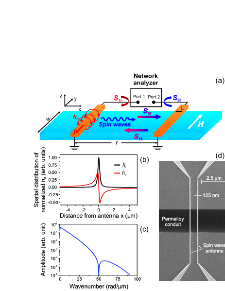
Spin wave excitation and detection was performed via two identical Ti/Au antennas with widths in the range of and center-to-center distances ranging from 1.2 to 10 m, denoted below as . Each antenna is connected in series between a ground pad and another coplanar contact pad (Fig. 1). The antennas are RF powered and thus generate an oscillating RF field located essentially under the antennas and a weaker and anti-symmetric RF field located at the edges of the antennas [see example in Fig. 1(b)]. In this geometry, the RF fields will thus excite spin waves with wavevectors purely along the direction.
Static longitudinal fields saturating the magnetization along the stripe length lead to signals related to spin waves that are excited by at the antenna edges. However the associated signals (not shown) were one to two orders of magnitude smaller than when a transverse magnetic field was applied in the configuration depicted in Fig. 1(a). In the remainder of the paper, we focus on the case of a static field saturating the stripe magnetization in the transverse direction (Damon-Eshbach configuration), and thus study the properties of magnetostatic surface spin waves (MSSW) that are excited in this geometry.
The devices were characterized by measuring the magnetic field dependence of their complex scattering matrix with under 10 mW of excitation power. An on-chip full two-port calibration routine with a load-match-reflect standard impedance calibration kit was performed to correct for imperfections of the network analyzer, the cable assembly, and the RF probes. The pads connecting the device were short enough (300 m) that no deembedding was required. The phase error associated with this approximation is negligible compared to the phase accumulation due to propagation of spin waves through our devices, as shown below.
The signal transmission through the device comprises two superimposed signals: (i) a direct antenna-to-antenna parasitic coupling of typically -30 to -40 dB and (ii) smaller superimposed spin wave related signals. We construct an approximation of the scattering matrix of the parasitic transmission by calculating the average of the scattering matrix over all applied magnetic fields. We then isolate the spin-wave related signals by defining the complex admittance normalized to as:
| (1) |
The typical order of magnitude of is for , and , and seems to depend on the spin wave conduit width.
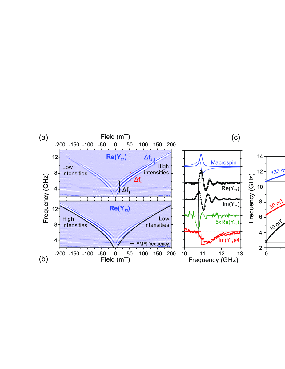
The basic behavior of the devices is illustrated in Figs. 2(a-c), which display the transmission and reflection properties for a stripe width of , a propagation distance of , and antenna widths of . The field-independent cross-talk is subtracted using Eq. 1. For a given magnetic field, the spin-wave transmission signal exists only above a certain frequency threshold and stays detectable within a frequency transmission band of width . In all cases, the onset of finite transmission comes together with a drop of the reflection signal [red line in Fig. 2(c)].
The frequency threshold shifts to higher frequencies upon increasing the magnetic field strength. We have found that it matches quantitatively the FMR condition [see Fig. 2(b)]. Here, is the gyromagnetic ratio and the shape anisotropy of the stripe has been neglected.
Conversely, the transmission band gets narrower as we increase the field strength. This behavior can be understood by looking at the expected dispersion relation of spin wavesKalinikos for several magnetic fields [see e.g. Fig. 2(d)]. The narrowing of transmission band stems from the fact that the antenna can excite spin waves only up to a finite wavenumber . The flattening of the dispersion relations at larger magnetic fields [Fig. 2(d)] then leads to a narrowing of the transmission band when the magnetic field is increased.
The shapes of the reflection and transmission signals [Fig. 2(c)] differ substantially: the transmission signals are complex numbers with real and imaginary parts that oscillate and decay with frequency, while the reflection signals do not oscillate and show a slightly less pronounced decay with frequency. The oscillation of the transmission signal is thus a phase rotation inherent to the propagation of the spin waves. The decay of the envelope of the reflection and transmission signals stems from the wavevector-dependent excitation efficiency. The faster decay of the propagation signals may be indicative of additional losses upon spin wave propagation.
A final striking point is the amplitude non reciprocity. For positive fields, the forward transmission is typically five times larger than the backward transmission, while the situation is reversed upon a change of the applied field direction (Fig. 2). This feature recalls the surface character of the MSSW of finite wavevector, and it will be discussed further below.
The main experimental features – frequency threshold to allow transmission, phase rotation upon transmission, and non reciprocity – can be accounted for by the following simple model. The pumping field has its components and its gradients along the stripe axis and stripe normal [Fig. 1(a)]. The dependence is due to RF absorption by Eddy currents and excitation of the (lossy) magnetic precession bailleul_shielding_2013 , and it has its importance since MSSW waves tend to localize at either the top or the bottom surface of a ferromagnetic film damon_magnetostatic_1961 ; kostylev_non-reciprocity_2013 , depending whether , M and form a direct or an indirect trihedron. The demagnetizing field within the stripe is quasi-uniform, except for a gradient of its component near the stripe edges. We have performed micromagnetic simulationsOOMMF and have found that a transverse bias field of 10 mT is enough to saturate the sample over of its width. All together, this provides in principle possibilities of exciting spin waves with propagating and components and with standing waves with near the edges.
Since spin waves with wavevectors perpendicular to the film plane have frequencies substantially above our region of investigation, we shall restrict our study to the case of . The main transmission channel relies on spin waves extending over the whole stripe width, so only spin waves with wavevectors purely along (Damon-Eshbach modes damon_magnetostatic_1961 ) will be included in the model. For long wavelength (i.e. ) spin waves of frequency the real part of the complex wavevector can be approximated by an exchange-free formulation:
| (2) |
where is the Heaviside distribution. From Fig. 2(d) one can observe that there is nearly no difference between the dispersion relations calculated with and without taking into account the exchange interaction in the studied wavevector range.
We approximate the Oersted field profile below the antenna by assuming that its -component is uniform in an interval and vanishes everywhere else. is the typical lateral extension of the RF field at the stripe altitude. The description is accurate only when [Fig. 1(b)] but we shall see that the details beyond the lateral extension of the RF field are not critical. Equivalently, the RF field can be described in reciprocal space by:
| (3) |
This field profile changes sign at a wavevector of : our excitation efficiency vanishes at this wavevector and its multiples [Fig. 1(c)].
We shall account for the overlap between the RF field profile and the exponential profile of the surface spinwaves by defining an ad-hoc -dependent pumping (or pick-up) efficiency factor:
| (4) |
If the center-to-center distance between the antennas is , the spinwave undergoes a phase rotation of along its propagation path, together with an exponential decay of rate , where is a mode-dependent function of the Gilbert damping. This can be described by a propagation operator
| (5) |
Note that each maximum in the real part of the propagation operator corresponds to a total propagation over an integer number of wavelength. This will be a convenient way to directly measure from the oscillatory experimental signals.
Overall, the scattering admittance elements of our system at a given frequency are proportional to the product of the stripe width, the dependence of the excitation field (from Eq. 3) at the corresponding wavevector (from Eq. 2), the detection sensitivity (also Eq. 3), the square of the pumping efficiency (Eq. 4) and the complex propagation operator (Eq. 5). This yields:
| (6) |
Note that because of the surface nature of MSSWs, will vary faster than and thus it will differ for forward and backward transmission coefficients. The difference increases with the wavevector, hence with frequency at a given applied magnetic field. This faster decay becomes clear in Fig. 2(c) when comparing forward (black) and backward (green) transmission signals. Note also that the transmission coefficients are complex numbers, with real and imaginary parts that rotate in quadrature thanks to the propagation operator. This is also in line with experiments. The reflection coefficients and can be obtained from Eq. 6 by setting the propagation distance to zero.
Equation 6 is compared quantitatively to the experimental data in Fig. 1(c). The main experimental features – oscillations in quadrature of the two components of the transmission parameters and overall decay with the frequency – are well reproduced with the propagation loss as single fitting parameter, which confirms that the essential physics is included in Eq. 6.
However, the onset of transmission near is much more gradual in the experiments than in the modeling. This shortfall of Eq. 6 results from the assumption of a bijective relation between wavevector and frequency (Eq. 2) while in reality any given mode has a finite susceptibility also below and above its eigenfrequency. For (FMR macrospin mode) the susceptibilities are symmetric and antisymmetric Lorentzian lines that show a finite spread around the mode center frequency (see Fig. 2(c) blue curves). The rigorous description of the onset of transmission at the threshold goes beyond the scope of this paper, but would require to include a convolution of the mode susceptibilities within the kernel of Eq. 6. One can notice that the experimental signals indeed resemble the convolution of the modeled response with a macrospin response [see Fig. 2(c)].
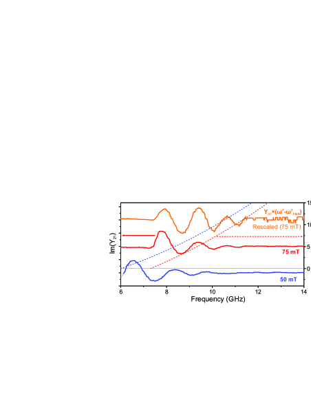
To be able to excite spin waves with an ultra-wide wavenumber band one must use antennas with smaller widths. For example, a 125 nm wide antenna can potentially excite spin waves with wavenumbers up to 50 rad/ (Fig. 1(c)). Figure 3 demonstrates that spin waves can be efficiently generated and sensed inductively by a such a narrow antenna. For the shortest propagation distance of , few oscillations of the transmission signals were detected. The corresponding signals could be satisfactorily accounted for an effective nm (fits not shown) which corresponds to a first lobe of Eq. 3 at . From the analysis of the dispersion relations calculated for different magnetic bias fields, we could estimate that the highest detected wavevector was (wavelength ), () and (), respectively. Our approach is very advantageous because it identifies the routes to access even higher wavevectors. An improvement of the wavevector capability requires the minimization of the effective antenna size by thinning the insulator that separates the antenna from the stripe, as well as a further shrinking of the antenna. Nevertheless, this will increase the parasitic cross-talk and thus a geometrical compromise will have to be found.
In summary, we have presented an inductive method to perform phase-resolved spectroscopy of propagating spin waves in thin Permalloy stripes. We demonstrate that very narrow antennas can be successfully used to generated and detect spin waves in a very wide range of wavevectors (up to ), which compares well with other techniques. Furthermore, we developed an analytic model to describe the main features of the spin-wave transmission functions as the dispersion relation or the non-reciprocity in propagation.
This work was supported by imec’s Industrial Affiliation Program on Beyond CMOS devices and by the French National Research Agency (ANR) under contract No. ANR-11-BS10-0003 lead by Matthieu Bailleul. F.C. thanks J. Loo for e-beam lithography, Rudy Caluwaerts for SEM images and imec’s clean room technical support.
References
- (1) A.V. Chumak, V.I. Vasyuchka, A.A. Serga, and B. Hillebrands, Nature Physics 11, 453 (2015).
- (2) K. Vogt, H. Schultheiss, S. Jain, J.E. Pearson, A. Hoffmann, S.D. Bader, and B. Hillebrands, Applied Physics Letters 101, 042410 (2012).
- (3) K. Vogt, F.Y. Fradin, J.E. Pearson, T. Sebastian, S.D. Bader, B. Hillebrands, A. Hoffmann, and H. Schultheiss, Nature Communications 5, 3727 (2014).
- (4) V.E. Demidov, S. Urazhdin, and S.O. Demokritov, Nature Materials 9, 984 (2010).
- (5) O. Rousseau, B. Rana, R. Anami, M. Yamada, K. Miura, S. Ogawa, and Y. Otani, Scientific Reports 5, 9873 (2015).
- (6) S. Klingler, P. Pirro, T. Brcher, B. Leven, B. Hillebrands, and A.V. Chumak, Applied Physics Letters 105, 152410 (2014).
- (7) V. Cherepanov, I. Kolokolov, and V. L’vov, Physics Reports 229, 81 (1993).
- (8) S.O. Demokritov, B. Hillebrands, and A.N. Slavin, Physics Reports 348, 441 (2001).
- (9) F. Fohr, A.A. Serga, T. Schneider, J. Hamrle, and B. Hillebrands, Review of Scientific Instruments 80, 043903 (2009).
- (10) S. Cherepov, P.K. Amiri, J.G. Alzate, K. Wong, M. Lewis, P. Upadhyaya, J. Nath, M. Bao, A. Bur, T. Wu, G.P. Carman, A. Khitun, and K.L. Wang, Applied Physics Letters 104, 082403 (2014).
- (11) C. Jegou, G. Agnus, T. Maroutian, V. Pillard, T. Devolder, P. Crozat, P. Lecoeur, and P. Aubert, Journal of Applied Physics 116, 204102 (2014).
- (12) H. Yu, G. Duerr, R. Huber, M. Bahr, T. Schwarze, F. Brandl, and D. Grundler, Nature Communications 4 (2013).
- (13) V. Vlaminck and M. Bailleul, Science 322, 410 (2008)
- (14) V. Vlaminck and M. Bailleul, Physical Review B 81, 014425 (2010).
- (15) B.A. Kalinikos and A.N. Slavin, Journal of Physics C: Solid State Physics 19, 7013 (1986).
- (16) M. Belmeguenai, J.-P. Adam, Y. Roussign, S. Eimer, T. Devolder, J.-V. Kim, S.M. Cherif, A. Stashkevich, and A. Thiaville, Physical Review B 91, 180405 (2015).
- (17) M. Bailleul, Applied Physics Letters 103, 192405 (2013).
- (18) R.W. Damon and J.R. Eshbach, Journal of Physics and Chemistry of Solids 19, 308 (1961).
- (19) M. Kostylev, Journal of Applied Physics 113, 053907 (2013).
- (20) The simulations were performed using the OOMMF open code: M.J. Donahue and D.G. Porter, NISTIR Report No. 6376, 1999.
- (21) C. Bayer, J. Jorzick, B. Hillebrands, S.O. Demokritov, R. Kouba, R. Bozinoski, A.N. Slavin, K.Y. Guslienko, D.V. Berkov, N.L. Gorn, and M.P. Kostylev, Physical Review B 72,064427 (2005).