A Response to arXiv:1512.09181, “Space Charge Limits in the DAEALUS DIC Compact Cyclotron”
Abstract
This document addresses concerns raised about possible limits, due to space charge, to the maximum ion beam current that can be injected into and accepted by a compact cyclotron. The discussion of the compact cyclotron is primarily within the context of the proposed DAEALUS and IsoDAR neutrino experiments. These concerns are examined by the collaboration and addressed individually. While some of the concerns are valid, and present serious challenges to the proposed program, the collaboration sees no immediate showstoppers. However, some of the issues raised clearly need to be addressed carefully - analytically, through simulation, and through experiments. In this report, the matter is discussed, references are given to work already done and future plans are outlined.
ntroduction
DAEALUS Alonso et al. (2010); Aberle et al. (2013); Abs et al. (2012); Calabretta et al. (2011); Conrad et al. (2012) is a proposed experiment to measure CP violation in the neutrino sector. To provide the necessary neutrino flux to obtain results in a 5 year measurement period, 10 mA of protons need to be accelerated to 800 MeV/amu and impinge on the target where they create neutrinos through pion and muon decay-at-rest. The system is envisioned to be a chain of two cyclotrons: the compact 60 MeV/amu DAEALUS Injector Cyclotron (DIC), that acts as a pre-accelerator, and the 800 MeV/amu DAEALUS Superconducting Ring Cyclotron (DSRC). Using only the DIC, an isotope decay-at-rest experiment can be setup, producing a very pure beam and a decisive search for sterile neutrinos can be anticipated. This project is called IsoDAR Bungau et al. (2012); Adelmann et al. (2012); Abs et al. (2015). Among the challenges for the DIC are the strong space charge effects of such a high intensity beam. Space charge matters most in the Low Energy Beam Transport Line (LEBT) and during injection into the cyclotron. Our concept to mitigate this problem is based on accelerating 5 mA of instead of 10 mA of protons, leading to the same number of nucleons on target at half the electrical current as the remaining electron bound in the molecular ion reduces the electrical current in the beam. In addition, stripping of this electron leads to very clean extraction from the DSRC.
Recently, a note appeared on arXiv Baartman (2015), discussing the issue of space charge during injection into the DIC and estimating the maximum achievable current in a compact cyclotron at about A. This is far from the 5 mA of beam current needed for the proposed experiment. The collaboration has carefully examined the presented arguments and found that, while there certainly is merit to them, matters are over-simplified in the published note and moreover, it does not take into account important published results Yang et al. (2013); Alonso et al. (2015).
In Section III the arguments are discussed in detail.
I xecutive Summary
In this note we carefully consider the arguments presented in Baartman (2015), and find that while some of the points are well-taken, the foundations are too weak for the strong statement that the maximum current to be expected from our system will never exceed A.
We agree that the perveance argument must be used with caution, and that comparing our DAEALUS Injector Cyclotron (DIC) with a high-current H- cyclotron is not appropriate. Space charge forces are directly related to the bunch charge density, and in H- machines, with substantially larger phase acceptance, the longitudinal extent of the bunch is considerably greater. In contrast, such a large phase acceptance cannot be tolerated in the DIC in which a good turn separation is required at extraction.
We also agree that the critical elements of our concept are the injection and first few turns. In our paper Yang et al. (2013) (not cited in Baartman (2015)), we developed a beam dynamics model, from 1.5 MeV/amu to extraction at 60 MeV/amu, showing that the beam can be accelerated and extracted with acceptable beam loss on the extraction septum. We also show that the vortex motion of the bunch provides good longitudinal and radial focusing, resulting in a quasi stationary bunch, similar to the PSI Injector 2. In a current research project, we are studying the beam dynamics through the axial injection channel, the spiral inflector, and acceleration through the first few turns to match, with the input conditions (at 1.5 MeV/amu) of the model developed in Yang et al. (2013).
We have already demonstrated that a larger inflector can be built; we have, in fact, tested a 15 mm gap inflector with good transmission of beams Alonso et al. (2015) (not cited in Baartman (2015)). This refutes the argument made in Baartman (2015) that “a bunch of 12 mm full 4 size would not fit through a reasonably-dimensioned inflector”.
Furthermore, Baartman (2015) does not acknowledge that our higher injection energy, leading to larger radius of the first turn, and the use of four high power RF cavities will provide very rapid acceleration of the injected beam with additional vertical focusing. We anticipate that these elements will be essential for the challenging matching process at the takeoff point of our published model in Yang et al. (2013).
This said, it is clear that careful and precise PIC simulations are required to establish the feasibility of the necessary injection and matching conditions. We are embarking on a program to do exactly this. The tools are in place now, following the enhancement of OPAL to include the 3D inflector geometry, and anticipate having suitable answers in an appropriate time frame.
II iscussion of the Concerns
In discussing the raised concerns, we will largely follow the structure of Baartman (2015) and add additional context as needed.
III.1 Generalized Perveance
In our publications, we often use the generalized perveance as a first order estimate of the strength of the space-charge effects in various parts of the DAEALUS system (LEBT, DIC, DSRC). In Reiser (2008), is given by:
| (1) |
with q, I, m, , and the charge, current, rest mass, and relativistic parameters of the particle beam, respectively, and the space charge compensation factor.
In (Baartman, 2015, Section 1), the applicability of the perveance argument is examined and it is pointed out that:
-
1.
The comparison between the average beam currents of a compact cyclotron and a compact H- cyclotron is erroneous, because space charge is a local effect and the phase acceptance of an H- machine is much larger, thus the bunches are longer and the peak currents are significantly lower.
-
2.
We are injecting at roughly double the energy of typical compact cyclotrons (70 keV instead of 30 keV) which indeed leads to lower perveance, but has the disadvantage that the transverse focusing is one quarter as large due to the injection radius being twice as large.
With respect to item 1 above, we acknowledge that the comparison of H- cyclotrons with a large acceptance (TR-30 Kuo et al. (1998) and CYCLONE-30 Vanderlinden et al. (1990)) and the DIC was made without taking the phase acceptance into account. Baartman (2015) correctly states that the phase acceptance of H- cyclotrons is about 60-70∘ and in the DIC it is only 20∘. Thus the average current is compressed into a smaller bunch and our peak current is about 90 mA for 5 mA DC equivalent average current (5 mA 360∘/ 20∘). In a H- machine the peak current would only be 30 mA .
With respect to item 2, we assume this argument is based on the 2D Model presented in (Baartman, 2015, Section 2.1) (briefly discussed in the next section here) and the envelope equation therein (cf. Equation 2). Indeed, if one were to compare H- and at the same velocity and in essentially the same machine (same tunes, same acceleration, etc.) and at the same current, according to the simple model, the situation for would be a factor 2 worse, due to the decrease of the focusing strength with turn radius squared. However, this argument does not truly apply to the DIC for two reasons: the design is indeed different and the envelope equation does not include important effects of beam dynamics (see discussions in the following sections).
Clearly, previous comparison with existing compact H- cyclotrons is obsolete and we should instead focus on the design choices we made to accommodate the higher rigidity of .
Ultimately, the feasibility of the project needs to be determined through careful analysis, a rigorous simulation study of the actual DIC design, and experiments.
III.2 A 2D Model?
In (Baartman, 2015, Section 2.1) the envelope equation in terms of perveance and tune is investigated briefly. Cited directly from Baartman (2015):
| (2) |
with , the radial and vertical envelope radii, the radial tune and the orbit radius.
We agree with the statement in the last paragraph of this section, i.e. a continuous beam modeled with the envelope equation is a not suitable model. This is due to the fact that complex particle dynamics present in space charge dominated beams, leading to vortex-motion and the formation of a round distribution in radial-longitudinal space, are not considered.
In addition, the DIC will differ from existing machines in several key aspects. The spiral inflector and cyclotron vertical gap will be sufficiently large to let a larger beam pass through. The energy gain per turn will be 2.4 to 2.6 times higher compared to that in proton cyclotrons, to expedite exit from of the central region and to achieve earlier development of a stabilizing vortex motion, leading to a stationary distribution. The DIC will have 4 double-gap dees and thus better vertical focusing with already at the 8th turn.
We thus conclude that all other statements made in Section 2 have no merit and only a fully 3D treatment of the particle dynamics and experimental results (and the comparison of the two) can determine the maximum achievable current in the DIC.
III.3 3D Modeling
Knowing that injection will be a challenging task, we first investigated the space charge dominated beam transport starting from 1.5 MeV/amu up to extraction of the DIC using the particle-in-cell (PIC) code OPAL Adelmann et al. (2015). These encouraging results are published in Yang et al. (2013) and were not referenced in Baartman (2015).
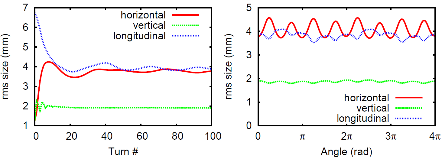
In Yang et al. (2013) we deliberately started with a mismatched and collimated beam, to mimic mismatch and study the reordering of the phase space (see Figure 1). Indeed we could show clearly that an almost stationary distribution is formed and the beam can be extracted with tolerable losses. Inspection of (Yang et al., 2013, Figure 6) provides evidence that the turn separation at injection and extraction is sufficient.
To conclude, we have carefully investigated the matching process that leads to a stationary and extractable distribution in the DIC. However, we did not yet include the spiral inflector in the model, this is part of an ongoing research project. The model presented in Baartman (2015), based on second order moments of the charge distribution, will not be able to reproduce in detail the complicated space charge dynamics, mostly because of the lack of non-linearities. Here we stress the fact that only a full 3D particle model can show us the final limits.
III.4 A Possible RFQ Injection Scheme
In (Baartman, 2015, Section 3.1), the author briefly discusses our ongoing investigation regarding the use of an RFQ as an injector to the DIC. The general idea of an RFQ direct injection scheme for compact cyclotrons was first published in 1981 by R.W. Hamm Hamm et al. (1982) and recently investigated together with Hamm for use in the DIC Winklehner et al. (2015). This recent investigation was prompted by the fact that the ion source used in the injection tests at Best Cyclotron Systems, Inc. Alonso et al. (2015) did not deliver the necessary current. As is pointed out in Abs et al. (2015), our primary design uses a conventional LEBT with a new improved ion source. The RFQ is an alternative design under investigation.
As we mention in Winklehner et al. (2015), the preliminary design produces a beam that de-bunches longitudinally and grows rapidly in the transverse direction. We are currently investigating the matching of the RFQ output beam to the spiral inflector and the cyclotron using OPAL. It was recognized in Winklehner et al. (2015) (and now confirmed in Baartman (2015)) that additional focusing and re-bunching will be necessary to make this system work. This is highly experimental and preliminary. However, dismissing the idea out-of-hand would be a mistake, because if it works, it could drastically relax the requirements of the injector ion source.
Regarding space charge compensation, it is true that transport through a conventional LEBT would yield higher compensation thereby leading to smaller emittances compared to the RFQ. However, starting at the entrance of the spiral inflector no compensation will be possible in either case due to the strong electric fields. Whether the increased emittance of the RFQ is prohibitively large will have to be determined through careful simulations as well.
III.5 Matching
In (Baartman, 2015, Section 3.2), it is stated that there is no way of matching the inflector output to the first turn optics.
Referring to the discussions and citations given above, we do not acknowledge the validity of the heuristic factor of 2 assumed in Baartman (2015) without justification. The ongoing effort to build a 3D beam dynamics model, including the spiral inflector and the full central region will allow us to understand the complicated matching process. In turn, this will provide a sound answer regarding the feasibility of our approach.
III.6 Theory Conclusions
The concluding theory section of (Baartman, 2015, Section 5) claims that 150 pC (5 mA at 33 MHz) bunches are impossible for 2 reasons:
-
1.
A bunch of 12 mm full 4 size would not fit through a ‘reasonably-dimensioned’ inflector.
-
2.
The resulting bunch occupies 54∘ RF.
However, in Alonso et al. (2015) (not cited in Baartman (2015)), we had described a test cyclotron for injection and the spiral inflector which has a gap of 15 mm. Tests showed that we could inject 6 mA DC, limited not by the cyclotron central region, but by the ion source current and LEBT. These values corresponded very well to simulations using OPAL. The simulations were later increased to 50 mA with similarly encouraging results. In Yang et al. (2013) we showed that even an initially mismatched beam that occupies more than the 10∘ RF will undergo vortex motion and within a few turns form a round distribution that can fit within this phase window.
The lessons we learned here are the following: a) the estimates presented in Baartman (2015) are very pessimistic and are (partially) refuted by the experiment. b) From this fact we can also conclude that our 3D model is closer to the nature than simplified estimates.
III.7 Envelope Evidence using TRANSOPTR
In (Baartman, 2015, Section 4) TRANSOPTR, a code based on the 3D envelope equation, including linear space charge was used. Several RFQ related scenarios were studied. These studies are certainly very interesting, however, the assumption of a fixed vertical tune of and no acceleration does not represent the true nature of this complicated part of the DIC.
Indeed the DIC is designed to work with 4 RF cavities, and the cavities can be operated, already from the first turn, with voltages of 70-80 kV, i.e. 16-30% higher than the usual 60 kV used in the H- compact cyclotron. The use of higher voltage is just a consequence of the larger radius of the cyclotron. Moreover, the larger gap mitigates the problem of a possibly large vertical size due to the initial . Additionally, the value of increases to 0.4 at the 4th turn and 0.5 at the 8th turn.
III.8 Ideally Placed Bunches with TRANSOPTR
In (Baartman, 2015, Section 5) the author uses TRANSOPTR to investigate the evolution of “ideally placed” bunches. In the final paragraph he concludes that the smallest bunch capable of containing the 150 pF would have to be roughly 6 mm in radius. Here we refer to Yang et al. (2013), not referenced in Baartman (2015), in which we did not start at turn one, but at 1.5 MeV/amu. In the near future we can also envision simulations starting at turn 1, especially to study the possible collimation scenarios.
V onclusions
The limits presented in Baartman (2015) are not the upper limits of the performance of compact cyclotron-based accelerator systems. In this note we give evidence partially through published models and partially through experiments. Extending these limits is the goal of our research program.
We note that the DAEdALUS situation may be considered analogous to the early days of the Paul Scherrer Institut 590 MeV meson factory, then called SIN (Swiss Institute for Nuclear-research). Skeptics were quite vocal about this cyclotron system never exceeding currents of 100 A Joho . As is now history, through careful and methodical improvements and upgrades, the proton current is now over 2.4 mA, nearly a factor of 25 higher with respect to the pessimistic estimates of experts in the past.
References
- Alonso et al. (2010) J. Alonso, F. Avignone, W. Barletta, R. Barlow, H. Baumgartner, A. Bernstein, E. Blucher, L. Bugel, L. Calabretta, L. Camilleri, et al., arXiv preprint arXiv:1006.0260 (2010).
- Aberle et al. (2013) C. Aberle, A. Adelmann, J. Alonso, W. Barletta, R. Barlow, L. Bartoszek, A. Bungau, A. Calanna, D. Campo, L. Calabretta, et al., arXiv preprint arXiv:1307.2949 (2013).
- Abs et al. (2012) M. Abs, A. Adelmann, J. Alonso, W. Barletta, R. Barlow, L. Calabretta, A. Calanna, D. Campo, L. Celona, J. Conrad, et al., arXiv preprint arXiv:1207.4895 (2012).
- Calabretta et al. (2011) L. Calabretta, L. Celona, S. Gammino, D. Rifuggiato, G. Ciavola, M. Maggiore, L. Piazza, J. Alonso, W. Barletta, A. Calanna, et al., arXiv preprint arXiv:1107.0652 (2011).
- Conrad et al. (2012) J. M. Conrad, D. Collaboration, et al., Nuclear Physics B-Proceedings Supplements 229, 386 (2012).
- Bungau et al. (2012) A. Bungau, A. Adelmann, J. R. Alonso, W. Barletta, R. Barlow, L. Bartoszek, L. Calabretta, A. Calanna, D. Campo, J. M. Conrad, Z. Djurcic, Y. Kamyshkov, M. H. Shaevitz, I. Shimizu, T. Smidt, J. Spitz, M. Wascko, L. A. Winslow, and J. J. Yang, Phys. Rev. Lett. 109, 141802 (2012).
- Adelmann et al. (2012) A. Adelmann, J. R. Alonso, W. Barletta, R. Barlow, L. Bartoszek, A. Bungau, L. Calabretta, A. Calanna, D. Campo, J. M. Conrad, Z. Djurcic, Y. Kamyshkov, H. Owen, M. H. Shaevitz, I. Shimizu, T. Smidt, J. Spitz, M. Toups, M. Wascko, L. A. Winslow, and J. J. Yang, arxiv:1210.4454 [physics.acc-ph] (2012).
- Abs et al. (2015) M. Abs, A. Adelmann, J. Alonso, S. Axani, W. Barletta, R. Barlow, L. Bartoszek, A. Bungau, L. Calabretta, A. Calanna, et al., arXiv preprint arXiv:1511.05130 (2015).
- Baartman (2015) R. Baartman, arXiv preprint arXiv:1512.09181 (2015).
- Yang et al. (2013) J. Yang, A. Adelmann, W. Barletta, L. Calabretta, A. Calanna, D. Campo, and J. Conrad, Nuclear Instruments and Methods in Physics Research Section A: Accelerators, Spectrometers, Detectors and Associated Equipment 704, 84 (2013).
- Alonso et al. (2015) J. Alonso, S. Axani, L. Calabretta, D. Campo, L. Celona, J. M. Conrad, A. Day, G. Castro, F. Labrecque, and D. Winklehner, Journal of Instrumentation 10, T10003 (2015).
- Reiser (2008) M. Reiser, Theory and design of charged particle beams, 2nd ed. (Wiley-VCH, Weinheim, 2008).
- Kuo et al. (1998) T. Kuo, R. Baartman, D. Yuan, K. Jayamanna, W. Uzat, R. P. H. Schneider, L. Root, R. Laxdal, and B. Milton, in Proc. 15th Intn. Conf. on Cyclotrons and their Applications (1998).
- Vanderlinden et al. (1990) T. Vanderlinden, E. Conrad, and Y. Jongen, in Proc. 2nd European Particle Accelerator Conference (1990) p. 437.
- Adelmann et al. (2015) A. Adelmann, A. Gsell, C. K. (PSI), Y. I. (IBM), S. R. (LANL), Y. Bi, C. Wang, J. Y. (CIAE), H. Z. T. University), S. Sheehy, C. R. (RAL), and C. M. (Cornell), The OPAL (Object Oriented Parallel Accelerator Library) Framework, Tech. Rep. PSI-PR-08-02 (Paul Scherrer Institut, (2008-2015)).
- Hamm et al. (1982) R. Hamm, D. Swenson, and T. Wangler, in 9. International conference on cyclotrons and their applications (1982).
- Winklehner et al. (2015) D. Winklehner, R. Hamm, J. Alonso, and J. Conrad, in 6th International Particle Accelerator Conference (IPAC2015) (2015).
- (18) W. Joho, private communication.