Gigantic directional asymmetry of luminescence in multiferroic CuB2O4
Abstract
We report direction dependent luminescence (DDL), i.e., the asymmetry in the luminescence intensity between the opposite directions of the emission, in multiferroic CuB2O4. Although it is well known that the optical constants can change with the reversal of the propagation direction of light in multiferroic materials, the largest asymmetry in the luminescence intensity was 0.5 so far. We have performed a measurement of photoluminescence with a He-Ne laser irradiation (633 nm). The luminescence intensity changes by about 70 with the reversal of the magnetic field due to the interference between the electric dipole and magnetic dipole transitions. We also demonstrate the imaging of the canted antiferromagnetic domain structure of (Cu,Ni)B2O4 by using the large DDL.
Magnetoelectric (ME) effect, the induction of magnetization by electric field or the induction of electric polarization by a magnetic field, has been intensively investigated in multiferroic materials Review . In addition to the static ME effect, multiferroic materials show novel optical phenomena, because the oscillating magnetic (electric) dipole moments can be induced also by electric (magnetic) fields of light. One typical example is non-reciprocal directional dichroism (NDD), a change in optical absorption with the reversal of the propagating direction of light (). Recent studies have revealed that a number of materials exhibit a large magnitude of NDD signal. Saito1 ; Saito2 ; Saito3 ; Saito4 ; Arima ; YTakahashi ; Kezs ; Bord ; Okamura ; YTakahashi2 ; onewaythz ; Kibayashi ; BiFeO3 . In contrast, there have been few reports on direction dependent luminescence (DDL), the asymmetry in the luminescence intensity between the opposite directions of emission. The first experimental observation of the DDL was reported by Rikken in a chiral Eu(()tfc)3 complex Rikken . The luminescence intensity of paramagnetic Eu3+ ions depends on whether the direction of the emission is parallel or antiparallel to the external magnetic field direction (magneto-chiral dichorism, MChD). Shimada investigated the DDL in paramagnetic rare-earth ions in ferroelectric (Ba,Sr)TiO3 and La2Ti2O7 in a magnetic field , and found that the luminescence intensity was dependent on the sign of ShimadaBaTiO3 ; ShimadaLa2Ti2O7 .
To the best of our knowledge, the DDL has been reported only in the paramagnetic materials, and the magnitudes of the DDL asymmetry are smaller than 0.5 ShimadaBaTiO3 . In this letter, we report DDL in a magnetically ordered noncentrosymmetric system. We performed a measurement of photoluminescence (PL) in multiferroic CuB2O4 with excitation by a He-Ne laser at 633 nm (1.96 eV). The observed DDL signal reaches 70 , which is about 100 times stronger than the previously reported value. Furthermore, we demonstrate that such a gigantic DDL gives a novel imaging technique for magnetic domain structures.
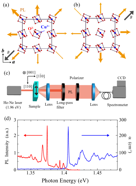
CuB2O4 crystallizes in a noncentrosymmetric tetragonal structure with a space group I2d crystal . Cu2+ ions occupy two inequivalent crystallographic sites denoted as and . Cu2+ ions at sites are surrounded by four O2- ions in planar square coordination with the site symmetry noncentrosymmetric . Cu2+ ions at B site are surrounded by six O2- ions. The electronic configuration of Cu2+ is (one hole) with . The material undergoes successive magnetic transitions at K and K. Below , magnetic moments at both and sites exhibit incommensurate helical order. Between and , magnetic moments of Cu2+ on sites exhibit commensurate canted antiferromagnetism, while magnetic moments of Cu2+ site remain disordered Petra2 ; Boehm1 ; Boehm2 . In the canted antiferromagnetic phase, the weak ferromagentic moment can be rotated in the plane with the application of a weak magnetic field of Oe Petra2 . Figures 1(a) and 1(b) show the magnetic structures in external magnetic fields in the and directions, respectively. The material shows ME effect explained by the modification of the metal-ligand hybridization with Cu2+ moments MetalLigand . The electric polarization is induced along the axis in an external magnetic field along the [110] axis, and unchanged with the reversal of the magnetic field Khanh . As a result, appears in the () direction in an external magnetic field in the () direction. Saito . reported gigantic NDD in this configuration for the near infrared light at 1.41 eV Saito1 , corresponding to the transition of a Cu2+ hole at sites from the ground state to the excited state SHG ; Pisarev . Here , , and denote the local coordinate axes at Cu sites, where is parallel to the crystallographic axis. The optical absorption coefficient changes by a factor of three with the reversal of a weak magnetic field of Oe. At a higher magnetic field, the material even shows one-way transparency of light, i.e., transparent for light propagating in one direction, while opaque for the light propagating in the opposite direction Oneway . Such a material may also show the gigantic DDL effect.
Single crystals of CuB2O4 and (Cu0.95Ni0.05)B2O4 were grown by a flux method PetraSupple . The crystals were oriented using Laue X-ray diffraction patterns. The thickness of each sample was 100 m with the widest faces . The sample was attached on a copper plate and cooled down with a closed-cycle refrigerator. We show in Fig. 1(c) the experimental setup for the PL measurement. The sample was excited with a 0.5 mW He-Ne laser of wavelength 633 nm polarized along the axis. The emitted light polarized along the [110] axis was chosen by an analyzing prism, and the PL spectrum was measured by using a grating-type optical spectrometer and a CCD detector.
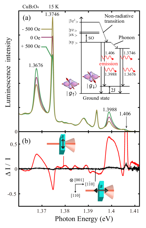
We show in Fig. 1(d) the optical spectra of absorption and luminescence for the light of and in zero magnetic field at K. The PL is observed below 1.406 eV, which corresponds to the zero-phonon absorption line at Cu sites, suggesting that the emitted light should originate from Cu sites. The zero phonon line at 1.406 eV is not strong for luminescence, because the emitted light is absorbed by the sample due to the large absorption peak. Figure 2(a) shows magnetic field dependence of the PL spectrum for the emitted light of and in an external magnetic field at K. The intensities of the luminescence peaks at 1.3988, 1.3746, and 1.3676 eV clearly change with the reversal of the magnetic field of Oe. We show in Fig. 2(b) the spectrum of the DDL signal at K. Here, and denote the luminescence intensity in zero magnetic field and the change in the luminescence intensity with the reversal of the magnetic field of Oe, respectively. The DDL signal appears in the Voigt configuration (), while it disappears in the Faraday configuration (), as expected from the group theory. The observed signal at 1.406 eV is not attributed to the DDL but the gigantic NDD effect. The other three peaks at 1.3988, 1.3746, and 1.3676 eV are attributed to the DDL, because the material does not show any optical absorption in this region. The energy shift of these peaks from the zero-phonon line at 1.406 eV are 7.2, 31.4, and 38.4 meV, respectively. The luminescence at 1.406 and 1.3988 eV can be assigned to the transitions to and , respectively. Here, and denote with the opposite spin direction, as shown in the inset in Fig. 2(a). The maximal energy gap between and is , where denotes the anitiferromagnetic exchange interaction. The observed energy shift of 7.2 meV well agrees with an inelastic neutron scattering study ( meV) Boehm3 . The spin-flopped state is however a linear combination of various one-magnon states. In fact, the luminescence peaks at 1.3988 and 1.3676 eV have a broad tail on the higher energy side. We assign the peaks at 1.3746 and 1.3676 eV to the transitions to and with one phonon, respectively, because the Raman scattering data suggests that there should be some lattice vibration modes around 30 meV PisarevRaman . We also measured magnetic field dependence of the optical absorption. The propagating direction of light with the smaller absorption at 1.406 eV coincide with the emission direction with the larger luminescence intensity at 1.3988 and 1.3676 eV, i.e., the direction with the smaller luminescence intensity at 1.3746 eV.
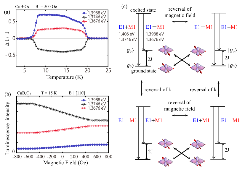
We show in Fig. 3(a) temperature dependence of the DDL signal at each peak position, measured in an external magnetic field of 500 Oe along the [110] axis. The gigantic DDL signal appears essentially in the canted antiferromagnetic phase. The signal disappears below K, corresponding to the transition from the canted antiferromagnetic phase to the helical phase. This evidently shows that the DDL should be ascribed to the magnetic order which breaks time reversal symmetry. Here one should note that the time reversal symmetry is revived in the low temperature helimagnetic phase. The DDL signal for the luminescence peak at 1.3988 eV is as large as at K, which is about 100 times stronger than the ever reported value in paramagnetic materials.
Next, we discuss the origin of the gigantic DDL signal. The DDL is understood in terms of the interference of the electric dipole (E1) and magnetic dipole (M1) transitions. According to Fermi’s golden rule, the intensities of the emission and for opposite propagating directions are written as
| (1) |
Here and represent the excited state and the ground state, respectively. and are the operators of the electric dipole and magnetic dipole transitions, respectively. Equation (1) explains that the interference of the E1 and M1 transitions results in the DDL. The previous research revealed that the excited state of Cu2+ ions at sites should be hybridized with and via the spin-orbit coupling Oneway . The transition from the ground state to is M1 allowed, while that to and are E1 allowed. The E1 and M1 transition interfere with each other for the emission process, in the same way as the absorption process.
We show in Fig. 3(b) magnetic field dependence of the PL intensity at K. Although the intensities of the luminescence peaks at 1.3988 and 1.3676 eV increase with magnetic field, that at 1.3746 eV decreases. The result suggests that the E1 transition constructively (destructively) interfere with the M1 transition for the transitions to () for the emission propagating in direction, while they destructively (constructively) interfere for the emission propagating in the opposite direction. The luminescence intensities for the transition to for the two propagation vectors are written as
| (2) |
while those to are given by
where and denote the excited states with the magnetic moment parallel and antiparallel to the magnetic field direction, respectively. is time-reversal operator. Equations (2) and (3) explain the experimental result, where the M1 and E1 transitions constructively (destructively) interfere for the transition to , when they destructively (constructively) interfere for that to . By the reversal of , the relative relation between the E1 and M1 transitions is flipped, as shown in Fig. 3(c).
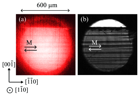
We have performed measurements of both PL image and optical transmission image in (Cu0.95NiB2O4. We have chosen this material, because the magnetic domain size is much larger than CuB2O4, which is an advantage for the optical imaging. Figure 4(a) displays the PL image taken at K after zero field cooling. The PL image was gained by using the luminescence peak around 1.3988 eV. Other luminescence lights were cut by short-pass filter. The magnetic domain structure is resolved as the contrast of the luminescence intensity. Figure 4(b) shows the transmission image obtained by the absorption at 1.406 eV, where the gigantic NDD is observed. We have confirmed that the PL image agrees with the transmission image. We note that there is no domain structure observed above nor below , as expected. This result confirms that the observed structure arises from the magnetic domain.
In conclusion, we have observed the gigantic DDL in CuB2O4. We succeeded in explaining the large DDL signal in terms of the interference between the electric dipole and magnetic dipole transitions. We have demonstrated that such nonreciprocal emission can be applied to the visualization of the magnetic domain structure. Since the NDD is reported in a number of materials, the DDL is not limited to CuB2O4, but may be also found in other multiferroic materials. The technique gives a novel tool to study magnetic domain structures of multiferroic materials which have large impacts in the field of spintronics.
This work was supported by Grant-in-Aid for JSPS Fellows (14J06840) and a Grant-in-Aid for Scientific Research from JSPS, JAPAN (24244045). S.T. acknowledges the financial support by JSPS through Program for Leading Graduate Schools (MERIT) and a research fellowship for young scientists.
References
- (1) For example, see M. Fiebig, J. Phys. D 38, R123 (2005); Y. Tokura, Science 312, 1481 (2006); N. Mazur and J. Scott, Nature (London) 442, 759 (2006); T. Arima, J. Phys. Soc. Japan 80, 052001 (2011).
- (2) M. Saito, K. Taniguchi, and T. Arima, J. Phys. Soc. Japan 77, 013705 (2008).
- (3) M. Saito, K. Ishikawa, K. Taniguchi, and T. Arima, Phys. Rev. Lett. 101, 117402 (2008).
- (4) M. Saito, K. Ishikawa, K. Taniguchi, and T. Arima, Appl. Phys. Ex. 1, 121302 (2008).
- (5) M. Saito, K. Ishikawa, S. Konno, K. Taniguchi, and T. Arima, Nat. Mater. 8, 634-638 (2009).
- (6) T. Arima, J. Phys. Condens. Matter 20, 434211 (2008).
- (7) I. Kezsmarki, N. Kida, H. Murakawa, S. Bordacs, Y. Onose, and Y. Tokura, Phys. Rev. Lett. 106, 057403 (2011).
- (8) Y. Takahashi, R. Shimano, Y. Kaneko, H. Murakawa, and Y. Tokura, Nat. Phys. 8, 121-125 (2012).
- (9) S. Bordcs, I. Kzsmrki, D. Szaller, L. Demk, N. Kida, H. Murakawa, Y. Onose, R. Shimano, T. Rm, U. Nagel, S. Miyahara, N. Furukawa, and Y. Tokura, Nat. Phys. 8, 734-738 (2012).
- (10) Y. Okamura, F. Kagawa, M. Mochizuki, M. Kubota, S. Seki, S. Ishiwata, M. Kawasaki, Y. Onose, and Y. Tokura, Nat. Commun. 4, 2391 (2013).
- (11) Y. Takahashi, Y. Yamasaki, and Y. Tokura, Phys. Rev. Lett. 111, 037204 (2013).
- (12) I. Kzsmrki, D. Szaller, S. Bordcs, V. Kocsis, Y. Tokunaga, Y. Taguchi, H. Murakawa, Y. Tokura, H. Engelkamp, T. Rm, and U. Nagel, Nat. Commun. 5, 3203 (2014).
- (13) S. Kibayashi, Y. Takahashi, S. Seki, and Y. Tokura, Nat. Commun. 5, 4583 (2014).
- (14) I. Kezsmarki, U. Nagel, S. Bordacs, R. S. Fishman, J. H. Lee, Hee Taek Yi, S.-W. Cheong, and T. Room, Phys. Rev. Lett. 115, 127203 (2015).
- (15) S. Toyoda, N. Abe, S. Kimura, Y. H. Matsuda, T. Nomura, A. Ikeda, S. Takeyama, and T. Arima, Phys. Rev. Lett. 115, 267207 (2015).
- (16) G. L. J. A. Rikken, E. Raupach, Nature (London) 390, 493-494 (1997).
- (17) Y. Shimada, M. Matsubara, Y. Kaneko, J. P. He, and Y. Tokura, Appl. Phys. Lett. 89, 101112 (2006).
- (18) Y. Shimada, H. Kiyama, and Y. Tokura, Phys. Rev. B 75, 245125 (2007).
- (19) M. Martinez-Ripoll, S. Martinez-Carrera, and S. Garcia-Blanco, Acta Cryst. B 27, 677 (1970).
- (20) G. A. Petrakovskii, D. Velikanov, A. Vorotinov, A. Balaev, K. Sablina, A. Amato, B. Roessli, J. Schefer, and U. Staub, J. Magn. Magn. Mater. 205, 105-109 (1999).
- (21) M. Boehm, B. Roessali, J. Schefer, B. Ouladdiaf, A. Amato, C. Baines, U. Staub, and G. A. Petrakovskii, Physica B 318, 277-281 (2002).
- (22) M. Boehm, B. Roessli, J. Schefer, A. S. Wills, B. Ouladdiaf, E. Lelievre-Berna, U. Staub, and G. A. Petrakovskii, Phys. Rev. B 68, 024405 (2003).
- (23) T. Arima, J. Phys. Soc. Jpn. 76, 073702 (2007).
- (24) N. D. Khanh, N. Abe, K. Kubo, M. Akaki, M. Tokunaga, T. Sasaki, and T. Arima, Phys. Rev. B 87, 184416 (2013).
- (25) R. V. Pisarev, I. Sanger, G. A. Petrakovskii, and M. Fiebig, Phys. Rev. Lett. 93, 037204 (2004).
- (26) R. V. Pisarev, A. M. Kalashnikova, O. Schps, and L. N. Bezmaternykh, Phys. Rev. B 84, 075160 (2011).
- (27) G. A. Petrakovskii, K. A. Sablina, D. A. Velikanov, A. M. Vorotynov, N. V. Volkov, and A. F. Bovina, Crystallogr. Rep. 45, 853-856 (2000).
- (28) M. Boehm, S. Martynov, B. Roessli, G. Petrakovskii, and J. Kulda, J. Magn. Magn. Mater. 250, 313-318 (2002).
- (29) R. V. Pisarev, K. N. Boldyrev, M. N. Popova, A. N. Smirnov, V. Y. Davydov, L. N. Bezmaternykh, M. B. Smirnov, and V. Y. Kazimirov, Phys. Rev. B 88, 024301 (2013).