Perpendicular laser cooling with a rotating wall potential in a Penning trap
Abstract
We investigate the impact of a rotating wall potential on perpendicular laser cooling in a Penning ion trap. By including energy exchange with the rotating wall, we extend previous Doppler laser cooling theory and show that low perpendicular temperatures are more readily achieved with a rotating wall than without. Detailed numerical studies determine optimal operating parameters for producing low temperature, stable 2-dimensional crystals, important for quantum information processing experiments employing Penning traps.
pacs:
37.10.Rs, 37.10.Ty, 52.27.JtI Introduction
Ion crystals confined in Penning traps provide opportunities for interesting studies in atomic physics Tan et al. (1995); Gruber et al. (2001); Shiga et al. (2011); Andelkovic et al. (2013), quantum information Biercuk et al. (2009); Britton et al. (2012); Wang et al. (2013); Mavadia et al. (2013); Bohnet et al. (2016), and plasma physics Anderegg et al. (2009); Jensen et al. (2005); Sawyer et al. (2012). Doppler laser cooling is the principle cooling technique used to generate the crystals. When the thermal energy of the ions is small compared to their Coulomb potential energy, ion crystals naturally form in order to minimize the ion Coulomb potential energy. Stable, low-temperature crystals are crucial for some applications. For example, simulations of quantum magnetism require stable single-plane crystals for single-ion detection. Low ion temperatures improve both the crystal stability and the fidelity of the simulations Britton et al. (2012); Sawyer et al. (2014); Bohnet et al. (2016).
Doppler laser cooling in a Penning trap is complicated by the fact that the ion crystals rotate, producing large, coherent Doppler shifts Itano and Wineland (1982); Itano et al. (1988); Hendricks et al. (2008); Asprusten et al. (2014). A theoretical treatment of this complication for a many-ion crystal (or a cold non-neutral plasma) and the resulting minimum attainable temperatures were discussed more than two decades ago Itano et al. (1988). Here we update this theory, taking into account an important experimental advance. Specifically, current experiments routinely apply sinusoidal potentials to azimuthally segmented trap electrodes to generate a rotating potential Huang et al. (1997, 1998); Mitchell et al. (1998); Bharadia et al. (2012). This rotating potential, frequently called a rotating wall, sets the rotation frequency and applies a torque that balances the torque imparted by the perpendicular laser cooling beam. We update previous theory Itano et al. (1988) by accounting for the work done by the rotating wall in applying a torque, and investigate in some detail the conditions that minimize the temperature. In addition we investigate the dependence of the Doppler cooling laser-beam torque on laser parameters and crystal rotation frequency. Conditions for minimal torque minimize shear stress, and may help in achieving stable crystals.
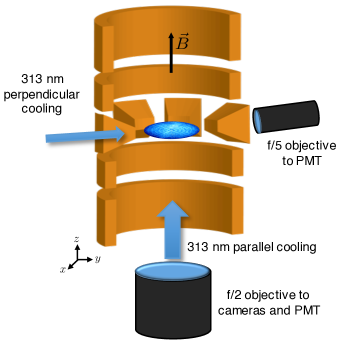
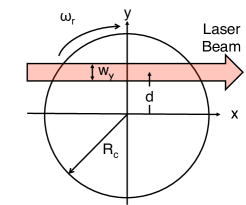
We study the single-plane crystal geometry sketched in Fig. 1 that is used in current National Institute of Standards and Technology (NIST) quantum simulation experiments Britton et al. (2012); Sawyer et al. (2014); Bohnet et al. (2016). In this work, Doppler laser cooling is provided by laser beams directed parallel and perpendicular to the magnetic field, which is oriented in the direction. We neglect any coupling between the in-plane (radial) and out-of-plane (axial) degrees of freedom, which should be weak for this single-plane geometry. We also initially neglect recoil heating of the in-plane degrees of freedom by the parallel laser beam. In this case the temperature of the in-plane degrees of freedom will be determined by the perpendicular laser and the problem is reduced to the 2-dimensional geometry diagrammed in Fig. 2. After analyzing this problem we add in the effects of scattering recoil from the parallel Doppler cooling laser beam.
A main conclusion of this manuscript is that low in-plane temperatures are more readily achieved with a rotating wall than without. Itano Itano et al. (1988) provided a careful theoretical and experimental study of perpendicular laser cooling in a Penning trap without a rotating wall and noted that, for a wide range of operating parameters, the minimum perpendicular temperature was two orders of magnitude larger than the normal single-ion Doppler cooling limit ( mK for the laser cooling transition in 9Be+). These higher temperatures are due to work done by the perpendicular laser in applying a torque that is necessary, in equilibrium, to balance ambient torques due to static field errors and asymmetries.
In general, static field errors due to imperfect trap construction result in a torque that tends to slow the crystal rotation Dubin and O’Neil (1999). Without a rotating wall, equilibrium, which is characterized by a constant rotation frequency and constant crystal radius , occurs when the perpendicular laser beam applies a counterbalancing torque that has the same sign as the rotation . In applying this torque the laser beam performs work, increasing the energy of the crystal. For constant and this energy input must go into increasing the in-plane thermal energy of the ions. Although static field errors generate a torque, they can only convert ion potential energy to ion thermal energy, or vice versa Dubin and O’Neil (1999). Therefore, in equilibrium static field errors can not change the ion thermal energy. In contrast, the rotating wall is generated with time-dependent potentials and can perform work, entering into the overall energy balance. In equilibrium the torque due to the rotating wall opposes the laser beam torque. The rotating wall can therefore provide an energy sink for the work done by the laser beam torque, resulting in lower in-plane temperatures.
In Sec. II, we write down expressions for the perpendicular laser scatter rate and torque, and discuss a simple theory for the energy balance between perpendicular Doppler laser cooling and the work done by the rotating wall. We also discuss recoil heating from the parallel laser beam. In Sec. III, we present numerical studies that vary the perpendicular cooling laser beam offset and waist, as well as the rotation rate of the crystal. These studies suggest optimal operating parameters that result in low in-plane temperatures and low laser beam torques. In Sec. IV we present some concluding remarks.
II Simple Theory
In this section we adapt the formalism of Itano Itano et al. (1988) to the experimental context of a 2-dimensional Coulomb crystal and obtain expressions for the photon scatter rate, rate of energy exchange, and torque due to a perpendicular cooling laser. We then add in an energy exchange contribution due to the rotating wall, and finally a recoil heating term due to a parallel cooling laser beam. Although the perpendicular cooling laser and rotating wall provide localized heating or cooling, we assume the in-plane degrees of freedom equilibrate rapidly and can be characterized by thermal equilibrium at a temperature foo . We are interested in determining as a function of the parameters outlined in Fig. 2. We neglect any coupling between the in-plane degrees of freedom and the parallel (to the -axis) degrees of freedom, anticipated to be a good approximation for single plane crystals.
II.1 Scattering Rate
The expression for the photon scattering rate for an ion with mass , position , and velocity in the laser beam of Fig. 2 is Itano et al. (1988)
| (1) |
where is the laser intensity, is the scattering cross-section on resonance, is the angular frequency of the laser light, is the natural linewidth of the targeted transition, and is the linewidth adjusted for saturation. is the detuning of the laser from the atomic transition frequency , taking recoil into account. is the wave vector of the laser light, which we approximate as , the wave vector on resonance, throughout the manuscript. We assume the laser beam has a Gaussian beam profile and is directed parallel to , in which case is the Doppler shift. The saturation adjusted linewidth can be written in terms of the saturation parameter as . With denoting the saturation parameter at maximum laser beam intensity, Eq. (1) can be rewritten as
| (2) |
In the remainder of the manuscript we neglect the multiplicative factor as it is very close to unity for the detunings we consider.
For calculating the total torque and energy exchange with the perpendicular laser beam we approximate the ion crystal as a continuous medium with areal density
| (3) |
where is the areal density at the center of the crystal. Equation (3) assumes a quadratic trap potential and is valid for a single-plane non-neutral plasma with sufficiently low temperature that the Debye length is small compared to . It results from the projection of a uniform density spheroid onto Dubin and O’Neil (1999); Dubin (2013).
The scattering rate per unit area is obtained by averaging the product of Eqs. (2) and (3) with a thermal distribution of velocities . Thermal equilibrium is characterized by a Maxwell-Boltzmann velocity distribution super-imposed on rigid-body rotation at Dubin and O’Neil (1999). For the -component of the velocity, this reduces to
| (4) |
where
| (5) |
The expression
| (6) |
can be integrated over the crystal to obtain the total photon scattering rate by the crystal.
II.2 Torque and Energy Transfer
We are particularly interested in expressions for the torque and energy exchange rate produced by the perpendicular laser cooling beam. The change in an ion’s momentum per photon scattering event, averaged over many scattering events, is . If these scattering events occur at the position in the crystal, they impart an average angular momentum per scattering event of . This transfer of angular momentum results in a torque imparted by the laser beam on the crystal given by
| (7) |
Note that we implicitly use the convention that , in which case when the laser applies a torque that tends to increase the rotation frequency, obtained for like that shown in Fig. 2.
Let denote the average change in the in-plane kinetic energy of an ion for a photon scattering event in the perpendicular laser beam. We determine the rate of energy change of the ion crystal produced by the perpendicular laser by multiplying with , , and and integrating over velocities and spatial coordinates. In three dimensions, Itano et al. (1988), where the recoil heating term has equal contributions from photon absorption and emission. For simplicity we assume an isotropic distribution of the scattered photons, in which case on average of the emitted photon recoil gets shared with the in-plane degrees of freedom, and gets shared with the axial (or transverse) degrees of freedom Itano and Wineland (1982). Because we assume no coupling between the in-plane and transverse degrees of freedom, we have , resulting in a total rate of energy change due to the cooling laser of
| (8) |
II.3 Energy Exchange with a Rotating Wall
The rotating wall performs work in applying a torque that maintains a constant rotation frequency. Experimental observation of stable rotation frequencies implies that the net torque on the crystal must be balanced. We assume the rotating wall and the laser provide the largest contributions to the torque, and neglect other sources of torque, such as gas collisions or static field asymmetries. This assumption is supported for our set-up by the observation of very slow evolution (time scale minutes) of the ion cloud equilibrium in the absence of the perpendicular cooling laser and the rotating wall Jensen et al. (2004). Therefore, in equilibrium , and the work done by the rotating wall is
| (9) |
where the torque of the laser is obtained from Eq. (7). Note that for (configuration of Fig. 2) the rotating wall is an energy sink, producing lower .
Equations (7), (8), and (9) can be combined to give an expression for the total energy balance due to both the laser and the rotating wall,
| (10) |
For numerical calculation we make the substitution , which simplifies the Maxwell-Boltzmann distribution and the term for the energy change per scattering event, while adjusting the denominator of . Substituting for , we obtain,
| (11) |
Roots of as a function of determine the Doppler cooling limit through (Eq. 5).
II.4 Recoil Heating from a Parallel Cooling Beam
Our primary interest is in the roots of Eq. (11). However, our Penning trap features a parallel cooling laser beam (see Fig. 1) that Doppler cools ion motion parallel to (the magnetic field direction) but, through photon recoil, heats the in-plane motion. We approximately model this recoil heating to determine under what conditions it can significantly elevate the in-plane temperature.
We account for recoil heating with a parallel cooling laser by adding a constant term to the energy balance equation (Eq. (11)). We estimate this term with some simplifying assumptions. First, we assume the parallel laser beam waist is large compared to (typical for our set-up), so that the parallel laser beam intensity and saturation parameter can be treated as constants for all ions in the crystal. We assume the parallel laser beam frequency is, in general, different from the perpendicular laser beam frequency, and set half a linewidth below the atomic transition frequency, , where the Doppler laser cooling limit for is achieved Sawyer et al. (2012, 2014); Mavadia et al. (2014). At the Doppler cooling limit the thermal broadening of the natural Lorentzian line profile is small. We therefore neglect Doppler shifts and obtain a parallel laser scatter rate per ion of
| (12) |
With the assumption of isotropic scattering, on average of the emitted photon recoil gets shared with the in-plane degrees of freedom. Finally gets multiplied by the number of ions in the crystal, obtained by integrating Eq. (3). This provides the following estimate for the parallel laser recoil heating rate,
| (13) |
In our approximate treatment of recoil heating from the parallel cooling beam we have ignored the additional saturation of the cooling transition for ions that are interacting with both laser beams at the same time. Our treatment should be reasonably accurate for low parallel laser intensities.
II.5 Simplifications for
Equation (11) can be simplified in the limit , conditions typically employed in experiments. This enables a more transparent determination of the dependence of the Doppler cooling limits on combinations of parameters. For , contributions to the integral in Eq. (11) occur predominantly for . Over this range we separate the 2-d density into a product of terms that separately depend on and ,
| (14) |
The region where this approximation fails is small, and also characterized by low areal density, therefore not significantly contributing to the integral. The term can be factored outside the and integrals, and with the assumption , the limits of the integral can be extended to ,
| (15) |
The bottom line of Eq. (15) no longer depends on . It is clear that roots to Eq. (15) must be roots of the bottom line involving integrals only over and . For now we approximate and write the bottom line in terms of dimensionless parameters and variables,
| (16) |
Here is an effective recoil velocity, , and we neglect any multiplicative constants. Roots of Eq. (16) for depend on the single-ion parameters and , and on two parameters that depend on properties of the crystal and the laser beam. They are the detuning of the laser from the Doppler-shifted atomic resonance at the center of the laser beam,
| (17) |
and the dispersion in the Doppler shift across the laser beam waist,
| (18) |
Both of these parameters are normalized to the half linewidth of the atomic transition. The equilibrium temperatures predicted by Eq. (16) are independent of the crystal radius .
We can include the lowest order correction to the dependence of the density on , . This term can be combined with the multiplicative term in Eq. (15). After adding the exponents, expanding, and completing the square, we obtain, up to a constant multiplicative factor, another Gaussian beam profile with a rescaled position and waist ,
| (19) | ||||
| (20) |
If the saturation parameter is sufficiently small so that the term in the denominator of Eq. (15) can be neglected, then the Doppler laser cooling limits will depend on the same combination of parameters as Eqs. (17) and (18) but with and replaced by and .
III Numerical Studies
We use the theory of the previous section to conduct a numerical study of the Doppler laser cooling limit and laser beam torque as a function of experimental parameters. We start by determining the Doppler laser cooling limits through the roots of the Eq. (16), valid for . We then present some examples of Doppler laser cooling limits obtained with the more general Eq. (11), and assess the region of validity of the simplifying assumption. Calculations of the laser torque from Eq. (7) are used to determine conditions that minimize shear stress on the crystal.
III.1 Doppler cooling limits for
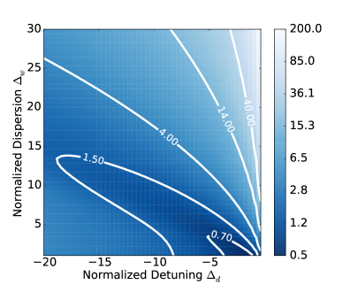
Figure 3 displays the Doppler laser cooling limits obtained from the values of that cause expression (16) to vanish. We use 9Be+ as an example, where, for the laser cooling transition, nm, MHz, and m/s. For a given , the equilibrium temperature goes through a minimum at a value of that is slightly larger than . This minimum grows with increasing . Low within a factor of two of the 0.44 mK single-ion Doppler laser cooling limit is obtained for a range of values for and satisfying and . For (upper right hand corner of Fig. 3) large values of are obtained, as this condition results in some ions scattering laser light that is blue detuned to the Doppler shifted atomic transition frequency.
III.2 General cooling limits and applied laser torque
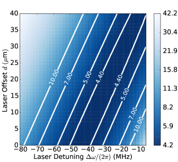
Roots of Eq. (11) provide Doppler laser cooling limits that do not require small laser waist and offset . Figure 4(a) displays contours of the equilibrium planar temperature obtained from Eq. (11), as a function of detuning of the laser beam from the atomic transition frequency and the offset of the laser beam from the center of the crystal. A rotation rate , beam waist , and crystal radius is assumed. For this plot is well satisfied, and we anticipate that the Doppler laser cooling limit should depend only on the combination (Eq. (17)). Indeed linear contour lines are observed, surrounding a low temperature “trough” where . The observed slope of the contour lines is , in good agreement with the predicted slope of . (Here we include the lowest order correction due to non-uniform density, given by Eq. (20).) The figure documents that, with the rotating wall, low Doppler cooling limits can be obtained over a wide range of laser detunings and offsets.
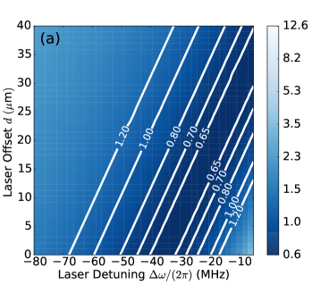
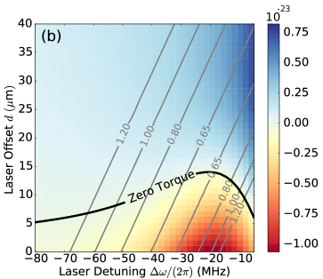
Figure 4(b) shows the same temperature contour lines superimposed on a calculation of the torque imparted by the perpendicular cooling laser beam. This torque is balanced by a torque of equal magnitude but opposite sign generated by the rotating wall. Because the rotating wall torque is applied on the boundary of the crystal while the laser torque is imparted in the crystal interior, conditions for zero laser torque should minimize shear stress, potentially important for producing stable crystals in which the ions do not move. Points of zero laser torque are indicated by the black curve in Fig. 4(b). Zero torque occurs for offsets . This is because the finite waist of the laser beam means a small part of the beam interacts with ions on the side of the crystal. Due to rotationally induced Doppler shifts, these ions scatter closer to resonance, leading to a balance with the torque generated by scattering. For the conditions of Fig. 4(b), the minimum with zero laser torque is obtained for a laser detuning ( half linewidths ) and an offset ( laser beam waist).
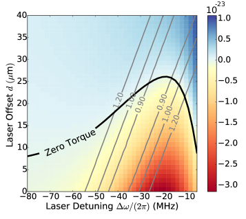
Figures 5 and 6 show numerical calculations similar to Fig. 4(b) of the equilibrium temperature contours and the laser torque for a larger beam waist (Fig. 5) and a higher rotation frequency (Fig. 6). Features similar to Figs. 4(a) and 4(b) are observed. In Fig. 5 the laser beam waist has been changed from in Fig. 4 to . The simplified analysis of Eq. (16) predicts temperature contours with the same slope as Fig. 4. Linear and approximately parallel contour lines surrounding a low temperature trough where are observed. The slope of these contour lines is , which differs from the contour line slope in Fig. 4, and also the predicted slope including the correction for the non-uniform density, . This indicates that the obtained with a 60 laser beam waist ( exhibits some deviations from the simplified analysis of Eqs. (16) to (20). The minimum with zero laser torque is obtained for a laser detuning ( half linewidths ) and an offset ( laser beam waist).
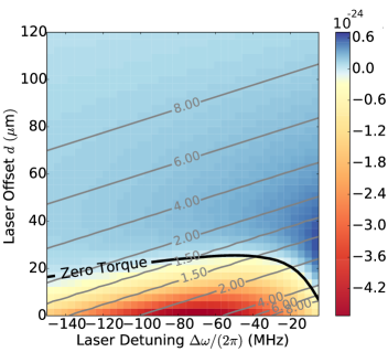
Recent NIST work uses an axial confinement (along the magnetic field) of MHz that results in rotation frequencies kHz Bohnet et al. (2016). Figure 6 shows the calculated for (same as Fig. 4) but with kHz. The measured slope of the contour lines, , agrees well with the predictions from the simplified analysis, . The larger rotation frequency produces a larger dispersion in the Doppler shift across the laser beam waist, resulting in an increase in the minimum temperature of . The detuning that results in both the minimum temperature and the zero laser torque is significantly increased to ( half linewidths). The laser beam offset for this condition is slightly increased from Fig. 4, ( laser beam waist). The greater sensitivity of to changes in the offset suggests that beam-pointing stability becomes a greater concern as the rotation frequency is increased.
III.3 Recoil Heating with the Parallel Beam
As discussed in Sec. II.4, experiments employ laser cooling with beams directed perpendicular and parallel to the magnetic field. Doppler laser cooling of the parallel degrees of freedom is straightforward. In contrast to the perpendicular motion, there is no coherent non-thermal motion and all ions scatter parallel laser light more or less equally. This means the parallel laser beam scatter rate can be significantly larger than the perpendicular laser beam scatter rate. Recoil heating of due to parallel laser light scattering is therefore a concern.
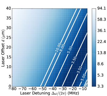
Figures 7 and 8 document that recoil heating from the parallel laser beam can be significant. These figures show a calculation of for parameters identical to those used in Figs. 4 and 5, but with recoil heating from a parallel laser beam with a saturation parameter of . The basic features of a low-temperature trough surrounded by approximately linear temperature contours is maintained, but in both figures the minimum perpendicular temperature has increased by a factor of five.
IV Conclusion
We updated existing theory for the laser cooling of 2-dimensional crystals of ions in a Penning trap to include energy exchange with a rotating wall potential. In contrast to theory and experimental measurements that did not use the rotating wall Itano et al. (1988), we find that low in-plane temperatures within a factor of two or three of the normal single-ion Doppler laser cooling limit can be obtained over a wide range of laser beam parameters and ion crystal rotation frequencies.
We also analyzed conditions for minimizing the torque imparted by the perpendicular laser-cooling beam. Low torque minimizes shear stress, which may increase the stability of the ion crystals. We find zero torque and the lowest are obtained with relatively large laser detunings that depend in detail on the ion crystal rotation frequency and laser beam waist. In general, optimization of the perpendicular laser beam cooling requires a different laser frequency and a set-up with greater flexibility than the parallel cooling. Finally, the relative strengths of the perpendicular and parallel laser beam scattering rates must be monitored to limit the impact of recoil heating from the parallel laser beam. This becomes particularly important as the crystal radius is increased, because for uniform parallel beam illumination, the recoil heating grows as .
The theory discussed here neglected any coupling between the in-plane degrees of freedom and the transverse (or parallel to the -axis) degrees of freedom. In addition it assumed that the in-plane degrees of freedom thermalize sufficiently rapidly that they can be described by thermal equilibrium characterized by a single temperature . It would be useful to test the validity of these assumptions, which could be pursued through a first-principles simulation of the ion dynamics and the laser beam scattering. A first-principles simulation could also investigate the level of torque required to produce shear-induced instabilities of the ion positions within the crystal.
V Acknowledgements
We acknowledge useful discussions with D. H. E. Dubin, R. C. Thompson, A. Keith, and D. Meiser. We thank K. Gilmore and R. Fox for their comments on the manuscript. SBT was supported by Summer Undergraduate Research Fellowship funding through NIST. JGB was supported by a NIST NRC postdoctoral fellowship. This manuscript is a contribution of NIST and not subject to U.S. copyright.
References
- Tan et al. (1995) J. N. Tan, J. J. Bollinger, B. Jelenković, and D. J. Wineland, Phys. Rev. Lett. 75, 4198 (1995).
- Gruber et al. (2001) L. Gruber, J. P. Holder, J. Steiger, B. R. Beck, H. E. DeWitt, J. Glassman, J. W. McDonald, D. A. Church, and D. Schneider, Phys. Rev. Lett. 86, 636 (2001).
- Shiga et al. (2011) N. Shiga, W. M. Itano, and J. J. Bollinger, Phys. Rev. A 84, 012510 (2011).
- Andelkovic et al. (2013) Z. Andelkovic, R. Cazan, W. Nortershauser, S. Bharadia, D. M. Segal, R. C. Thompson, R. Johren, J. Vollbrecht, V. Hannen, and M. Vogel, Phys. Rev. A 87, 033423 (2013).
- Biercuk et al. (2009) M. J. Biercuk, H. Uys, A. P. V. Devender, N. Shiga, W. M. Itano, and J. J. Bollinger, Quan. Inf. Comp. 9, 920 (2009).
- Britton et al. (2012) J. W. Britton, B. C. Sawyer, A. Keith, C.-C. J. Wang, J. K. Freericks, H. Uys, M. J. Biercuk, and J. Bollinger, Nature 484, 489 (2012).
- Wang et al. (2013) C.-C. Wang, A. C. Keith, and J. K. Freericks, Phys. Rev. A 87, 013422 (2013).
- Mavadia et al. (2013) S. Mavadia, J. F. Goodwin, G. Stutter, S. Bharadia, D. R. Crick, D. M. Segal, and R. C. Thompson, Nature Comm. 4, 2571 (2013).
- Bohnet et al. (2016) J. G. Bohnet, B. C. Sawyer, J. W. Britton, M. L. Wall, A. M. Rey, M. Foss-Feig, and J. J. Bollinger, arXiv:1512.03756 (2016).
- Anderegg et al. (2009) F. Anderegg, D. H. E. Dubin, T. M. O’Neil, and C. F. Driscoll, Phys. Rev. Lett. 102, 185001 (2009).
- Jensen et al. (2005) M. J. Jensen, T. Hasegawa, J. J. Bollinger, and D. H. E. Dubin, Phys. Rev. Lett. 94, 025001 (2005).
- Sawyer et al. (2012) B. C. Sawyer, J. W. Britton, A. C. Keith, C.-C. J. Wang, J. K. Freericks, H. Uys, M. J. Biercuk, and J. J. Bollinger, Phys. Rev. Lett. 108, 213003 (2012).
- Sawyer et al. (2014) B. C. Sawyer, J. W. Britton, and J. J. Bollinger, Phys. Rev. A 89, 033408 (2014).
- Itano and Wineland (1982) W. M. Itano and D. J. Wineland, Phys. Rev. A 25, 35 (1982).
- Itano et al. (1988) W. M. Itano, L. R. Brewer, D. J. Larson, and D. J. Wineland, Phys. Rev. A 38, 5698 (1988).
- Hendricks et al. (2008) R. J. Hendricks, E. Phillips, D. M. Segal, and R. C. Thompson, J. Phys. B 41, 035301 (2008).
- Asprusten et al. (2014) M. Asprusten, S. Worthington, and R. C. Thompson, Appl. Phys. B 114, 157 (2014).
- Huang et al. (1997) X.-P. Huang, F. Anderegg, E. M. Hollmann, C. F. Driscoll, and T. M. O’Neil, Phys. Rev. Lett. 78, 875 (1997).
- Huang et al. (1998) X.-P. Huang, J. J. Bollinger, T. B. Mitchell, W. M. Itano, and D. H. E. Dubin, Phys. Plasmas 5, 1656 (1998).
- Mitchell et al. (1998) T. B. Mitchell, J. J. Bollinger, D. H. E. Dubin, X.-P. Huang, W. M. Itano, and R. H. Baughman, Science 282, 1290 (1998).
- Bharadia et al. (2012) S. Bharadia, M. Vogel, D. M. Segal, and R. C. Thompson, Appl. Phys. B 107, 1105 (2012).
- Dubin and O’Neil (1999) D. H. E. Dubin and T. M. O’Neil, Rev. Mod. Phys. 71, 87 (1999).
- (23) We note that for a quadratic trap potential thermal equilibration of the magnetron and cyclotron center-of-mass modes may not be a reasonable assumption.
- Dubin (2013) D. H. E. Dubin, Phys. Rev. A 88, 013403 (2013).
- Jensen et al. (2004) M. J. Jensen, T. Hasegawa, and J. J. Bollinger, Phys. Rev. A 70, 033401 (2004).
- Mavadia et al. (2014) S. Mavadia, G. Stutter, J. F. Goodwin, D. R. Crick, R. C. Thompson, and D. M. Segal, Phys. Rev. A 89, 032502 (2014).