Providing Dynamic TXOP for QoS Support of Video Transmission in IEEE 802.11e WLANs
Abstract
The IEEE 802.11e standard introduced by IEEE 802.11 Task Group E (TGe) enhances the Quality of Service (QoS) by means of HCF Controlled Channel Access (HCCA). The scheduler of HCCA allocates Transmission Opportunitys (TXOPs) to QoS-enabled Station (QSTA) based on their TS Specifications (TSPECs) negotiated at the traffic setup time so that it is only efficient for Constant Bit Rate (CBR) applications. However, Variable Bit Rate (VBR) traffics are not efficiently supported as they exhibit non-deterministic profile during the time. In this paper, we present a dynamic TXOP assignment Scheduling Algorithm for supporting the video traffics transmission over IEEE 802.11e wireless networks. This algorithm uses a piggybacked information about the size of the subsequent video frames of the uplink traffic to assist the Hybrid Coordinator accurately assign the TXOP according to the fast changes in the VBR profile. The proposed scheduling algorithm has been evaluated using simulation with different variability level video streams. The simulation results show that the proposed algorithm reduces the delay experienced by VBR traffic streams comparable to HCCA scheduler due to the accurate assignment of the TXOP which preserve the channel time for transmission.
1 Introduction
Due to the wide spread of ubiquitous applications in the internet and the rapid growth of multimedia streams, providing differentiated QoS for such applications in Wireless Local Area Networks (WLANs) has become a very challenging task. The IEEE802.11 [1] has become the most deployed technology in WLANs due to some of its key features like deployment flexibility, infrastructure simplicity and cost effectiveness. IEEE802.11 introduces two channel access modes, namely Distributed Coordination Function (DCF) and Point Coordination Function (PCF). The former is the mandatory medium access method which is appropriate to serve best effort applications such as Hypertext Transfer Protocol (HTTP), File Transfer Protocol (FTP) and Simple Mail Transfer Protocol (SMTP). Multimedia streams that require a certain QoS level are served during the controlled mode (i.e. PCF) since it provides a contention-free polling-based access to the channel to provide the demanded QoS. However, it is not efficient enough to support high QoS requirement applications due to the fact that PCF only operates on the Free-Contention period, which may noticeably cause an increase in the transmission delay especially with high bursty traffics. Consequently, IEEE 802.11 TGe has presented IEEE 802.11e protocol [2] and revised version [3] with new technical enhancements on Medium Access Control (MAC) and Physical layer.
IEEE 802.11e introduces Hybrid Coordination Function (HCF) which extends the MAC of IEEE 802.11 standard. Enhanced Distributed Channel Access (EDCA) function is an extension to DCF, which operates in a distributed manner to provide prioritized QoS. HCCA is an extension of PCF that introduces a polling mechanism to provide parameterized QoS for applications that require rigorous QoS requirements. EDCA introduces a random access to the wireless medium by means of access categories (ACs). The traffics are mapped to ACs according to their priority. Every Access Categorie (AC) will be associated with a backoff timer so that the highest priority ACs will go through a shorter backoff process. Despite EDCA provides QoS support, it is still not efficient for application with rigid QoS requirements. Delay-sensitive multimedia streams are more adequate to be transmitted throughout HCCA since it was designated to minimize the overhead of messaging caused by the distributed approach of EDCA and thus guarantee the required better QoS. In HCCA, the Hybrid Coordinator (HC) polls wireless stations periodically and allocates TXOP to them. And yet, HCCA schedules traffics upon their QoS requirements negotiated in the first place, it is only suitable for CBR applications such as G.711 [4], audio streams, and (H.261/MPEG-1) video [5]. The allocation of the TXOP based on the mean characteristics negotiated at the traffic setup is not accurate, because of the deviation of VBR traffics from its mean characteristics. By 2014, about 91% of web traffic will be video streams [6]. For this reason several researches have been carried out to improve the performance of WLANs in terms of provisioning QoS for such streams. Motion Picture Experts Group type 4 (MPEG–4/H.264) has become a prominent video the internet due to its scalability, error robustness and network-friendly features. HCCA is not convenient to deal with the fluctuation of the VBR traffic such as MPEG–4 streams, where the packet size shows high variability during the time. This consequently leads to a remarkable increase in the end-to-end delay of the delivered traffics and degradation in the channel utilization.
With the increase of Internet web applications in the wireless mobile devices, the User-Generated Content (UGC) such as pre-recorded video streams has become more prominent nowadays. To the best of our knowledge, the scheduling of uplink pre-recorded continuous media in HCCA has not been addressed efficiently despite the fast growth of uplink streams of the UGC in the Internet such as pre-recorded video streams. In this paper, we present an enhancement on the HCCA scheduling algorithm aiming to adapt to the fast fluctuation of VBR video traffics profile. Basically, the proposed scheduling algorithm makes use of the fact that in the video applications that use prerecorded streams, the video traffic can be analyzed prior to the call setup. This fact has been highlighted in Feed Forward Bandwidth Indication .It computes the TXOP for a traffic based on knowledge about the actual frame size instead of assigning TXOP according to mean characteristics of the traffic which is unable to reflect the actual traffic. This algorithm uses the Queue Size (QS) of IEEE 802.11e MAC header to carry this information to the HC.
The rest of the paper is organized as follows. Section 2 illustrates the reference HCCA mechanism and its deficiency in supporting VBR Video streams and demonstrates some of the HCCA related works. Section 3 illustrates the proposed dynamic assignment algorithm. The performance evaluation and results discussion is shown in Section 4. Section 5 concludes the work presented in this paper.
2 Background and Related Works
This section describes IEEE 802.11e HCCA scheduler and some characteristics of MPEG–4 VBR video traffic. The deficiency of HCCA in supporting VBR is illustrated and some related works in enhancing its performance are also discussed.
2.1 IEEE 802.11e HCCA Mechanism
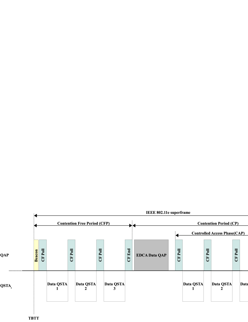
In IEEE 802.11e, a parameterized QoS is supported during HCCA using polling access method. A beacon is transmitted every Target Beacon Transmission Time (TBTT) comprising a superframe which in turn includes Contention Free Period (CFP) followed by Contention Period (CP). The HC shall initiate a CFP, to deliver its data traffics, or allocate a TXOP to a QSTA in CP to allow uplink traffics to be transmitted. In both cases the HC senses the Wireless Medium (WM). When the WM is found idle for a PCF Inter Frame Space (PIFS) period, the HC shall transmit its data during CFP period or permit a QSTA to start a frame exchange sequence with HC to cover the allocated TXOP duration. The HC may begin a Controlled Access Phase (CAP) at any time during the CP if the medium remains idle for a time equals to PCF PIFS. HCCA outperforms PCF of legacy IEEE802.11, in that it can be initiated in both CFP and CP in contrary to its ancestor, PCF, which only operates during CFP. When a station intends to initiate a data traffic, it issues a QoS reservation through a special QoS management action frame called ADDTS-Request contains a set of parameters that define the characteristics of the Traffic Stream (TS) (TSPEC). The fields of the TSPEC and how the HC exploits them in the scheduling process is discussed in details in the next section. Figure 1 demonstrates an example of HCCA transmission during CFP and CP periods.
2.2 HCCA Scheduler
As mentioned earlier, in order to initiate an uplink traffic, the QSTA issues a QoS reservation through transmitting an ADDTS-Request frame. This frame carries information about the TSPEC which is required by HC for scheduling purpose. The mandatory fields of the TSPEC are described as follows:
-
•
Mean Data Rate(): average data packet rate measured in units of (bits / seconds).
-
•
Nominal MSDU length(): mean size of MAC packets in units of bytes.
-
•
Maximum MSDU Size(): maximum allowable size of the MAC packet in the TS in units of bytes.
-
•
Delay Bound(): maximum allowable delay for a packet to be transmitted through the wireless medium in units of milliseconds.
-
•
Service Interval(): time period between a station’s Transmission Opportunities (TXOPs) measured in units of milliseconds.
-
•
Physical Rate(): the assumed wireless physical bit rate, measured in of (bits/second).
The HC which usually resides in the QoS-enabled Acces Point (QAP) maintains the TSPECs of all TSs in the so-called polling list. Accordingly, HC computes the duration of the time to be granted to each QSTA for the transmission of their traffics (TXOP). The admission of the TSs is governed by HC, using the Admission Control Unit (ACU). HC reserves the right to accept or reject any TS so as to preserve the QoS of the previously admitted TSs. If HC accepts the traffic it will respond by an ADDTS-Response or a rejection message otherwise.
Upon receiving an ADDTS-Request from a QSTA, the HCCA scheduler of the HC goes through the following steps to schedule the uplink traffics:
-
1.
SI Assignment
The scheduler calculates as the minimum of all Maximum Service Intervals () of all admitted traffic streams which is a submultiple of the beacon interval. The minimum for each QSTA is obtained from Equation (1).
(1) where is the number of admitted TSs and is the maximum of the stream. The is computed so that it satisfies the condition in Equation (2).
(2) where the denominator, , is an integer number that divides the beacon interval into the largest number that is equal or less than the .
-
2.
TXOP Allocation
HC allocates a TXOP to each admitted QSTA so as to enable it to transmit its data with regards to the negotiated QoS parameters of the TSPEC.
For the QSTA, the scheduler computes the number of MSDUs arrived at as in Equation (3).
(3) where is the nominal MAC Service Data Unit (MSDU) length for the QSTA. Then the TXOP duration of the particular station, , is calculated as the maximum of the time required to transmit MSDU or the time to transmit one maximum MSDU at the physical rate , as stated in Equation (4).
(4) Where is the maximum MSDU and denotes the overhead, including MAC and Physical Layer mode (PHY) headers, Interframe Spaces (IFSs), and the acknowledgment and poll frames overheads.
-
3.
Admission Control
The ACU manages the TSs admission while maintaining the QoS of the already admitted ones. When a new TS demands an admission, the ACU First obtains a new as shown in the previous step and computes number of MSDUs arrived at the new using Equation (3). Next, it calculates the for the particular TS using Equation (4). Finally, ACU admits only the TS if the following inequality is satisfied.
(5) where is the number of currently admitted TSs, so that () represents the incoming TS, is the time interval between two consecutive TBTTs periods, beacon interval and is the duration reserved for EDCA. The HC sends an acceptance message (ADDTS-Response) to the requested QSTA if the condition in Equation (5) is true or send a rejection message otherwise. The accepted TS will be added to the polling list of the HC.
2.3 Variable Bit Rate MPEG–4 Video Traffic
MPEG–4 is an efficient video encoding covering a wide domain of bit rate coding ranging from low-bit-rate for wireless transmission up to higher quality beyond High Definition TV (HDTV) [7]. For this reason, MPEG–4 video coding has become from among the prominent videos in the internet nowadays.
In fact, MPEG–4 videos are encoded using different compression ratios which produce different levels of quality. Higher compression level generates lower-quality video with smaller mean frame sizes and smaller mean bit rate and vice versa. This variability in the compression level is adequate to transmit the video packets over the limited wireless network resources such as low bit rate. Table 1 displays excerpt of video trace file of Jurassic Park 1 movie [8] encoded using MPEG–4 at high quality. In MPEG–4 video coding, successive pictures of the coded video stream compose a Group of Picture (GoP) which identifies how the intra- (I-frame) and inter-frames (P- and B- frames) are ordered, we refer the reader to [9, 10, 11] for more details about MPEG–4 videos. In this excerpt, we display one GoP of encoded video which consists the pattern IBBPBBPBBPBB. One can notice that the frame are not sequenced chronologically, yet it is ordered according to the display time instead.
| Frame sequence | Frame type | Frame period (ms) | Frame size (byte) |
|---|---|---|---|
| 527 | I | 21120 | 8124 |
| 528 | B | 21040 | 6442 |
| 529 | B | 21080 | 6237 |
| 530 | P | 21240 | 7581 |
| 531 | B | 21160 | 6184 |
| 532 | B | 21200 | 6173 |
| 533 | P | 21360 | 7482 |
| 534 | B | 21280 | 6331 |
| 535 | B | 21320 | 6567 |
| 536 | P | 21480 | 7130 |
| 537 | B | 21400 | 6410 |
| 538 | B | 21440 | 6223 |
As it is mentioned above, HC schedules QSTAs with respect to their negotiated TSPEC parameters which represent the mean characteristics of the traffics. Basically, the weakness of HCCA in supporting VBR traffic is because of the lack of information about the abrupt changes of the traffic profile during the time, more particular the traffic burstiness issue. In the case of the transmission of prerecorded uplink video traffics, it will be beneficial to inform the HC about the changing in the video profile to accommodate the fast fluctuation of the traffic.
Several approaches such as [12, 13, 14, 15, 16] have been presented in the literature attempting to remedy the deficiency of the HCCA reference scheduler in supporting QoS for VBR traffics. However, these enhancements are still not sufficient to cope with the fast fluctuating nature of highly compressed video applications since the QSTAs are scheduled according to an estimation about the uplink TSs characteristic which may be far from the real traffics.
2.4 Transmission of MPEG–4 video in HCCA
Although HCCA guarantees a QoS for video traffic based on the required TSPEC parameters, there is a probability to have frames smaller than the mean negotiated MSDU size. Consequently, a larger TXOP than needed will be assigned to a QSTA causing wasting in wireless channel time and remarkable increase in the end-to-end delay. Figure 2 illustrates the effect of assigning TXOPs for VBR traffics based on the mean TSPEC parameters on increasing the packet delay and on the poor wireless channel utilization. Suppose there are three stations sending uplink video traffics to QAP. HC will accordingly assign , and to , and respectively. Assume that in any some or all the frames sent is considerably smaller than the negotiated MSDU for the TS, in this case the QSTA will only utilize a portion of the scheduled TXOP for sending its data as explained in the and . The next scheduled TXOP will initiate according to its scheduled time regardless the actual exploited time in the previous TXOP causing increases in the delay and wasting the channel time as well. This issue may be noticeably severe when the number of QSTA with VBR traffics increase. Moreover, in the transmission of the prerecorded video, the traffic behavior is known prior to the traffic setup. These observations motivate us to present an enhancement to HCCA scheduler in which HC exploits information sent by QSTA about the changes in the traffic profile so as to accurately assign TXOP to QSTA and advance the consecutive TXOPs to minimize the delay and add the residual wireless channel time to EDCA period. The proposed scheduling algorithm is presented in details in the next section.

3 Dynamic TXOP Assignment Scheduling Algorithm
HCCA scheduler computes the TXOP duration by estimating the amount of data expected to be transmitted by the QSTA during Service Interval (SI). This estimation is based on the TSPEC negotiated with HC which considers the mean characteristics of the traffic, Equation (4). The proposed scheduling algorithm described in this section is referred to as Dynamic Transmission Opportunity because it adapts TXOP duration based on the feedback of the next frame packet size reported by QSTAs. The proposed algorithm gives an actual TXOP needed by stations and ensures that the delay is minimized without jeopardizing the channel bandwidth. The delay experienced by the proceeding unused(wasted) TXOPs is minimized using this algorithm as illustrated in Figure 3. The scheduling parameters along with the scheduling operation are described below.

3.1 Scheduling Parameters
As the proposed scheduler operates based on the feedback, the HCCA scheduler will change some scheduling parameters in Equation (4) upon receiving a feedback from QSTA. Herein a description of these parameters:
3.1.1 Number of MSDUs Received in SI ()
Using Equation (3), the reference scheduler calculates the expected number of the received packets every SI based on the mean TSPEC parameters at the traffic setup phase. In our algorithm, this parameter is set to 1 as only one packet is expected to be received every SI.
3.1.2 Mean Size of MSDU ()
The HC updates in Equation (4) with regards to the information piggybacked with each packet received from a QSTA. In fact, this is the major part of the proposed algorithm in which the TXOP duration given to a QSTA is calculated dynamically to accommodate the actual packet size to be received at the QAP from an uplink TS.
3.2 The Mechanism of Dynamic TXOP assignment
In this algorithm, the exact MSDU size of the next frame of the uplink stream is obtained from the application layer through cross layering. This information is transmitted with each packet to the QAP carrying the next frame size. Upon a data frame reception, the HC recalculates the TXOP duration to be granted for a particular station in the next SI so as to adapt to the fast varying in VBR video traffic. Consequently, it minimizes the packet end-to-end delay and conserve the channel bandwidth. In this section, we present the description of TXOP operation at both QSTAs and the QAP.
3.2.1 Operation at the station
At the QSTA, information about the next MSDU frame size is obtained from the application layer via cross-layering. This information is carried in the QS field introduced by IEEE 802.11 standard [3] which is a part of the QoS Control field of the QoS data frame. The QS field is exploited in this approach for sending information about the next MSDU frame size to the QAP.
3.2.2 Operation at the access point
After the traffic setup phase, the QAP transmits the first poll frame granting the QSTA a TXOP duration. The station will accordingly transmit the first packet of its traffic to the QAP. Note that the inter-arrival time between encoded video traffic frames is a multiple of a fixed interval (typically 40 ms) depends on the encoding parameters. That is to say, it is expected to receive only one packet at a multiple of a designated interval. Details about the operation of our approach at QAP is reported in Fig. 4.
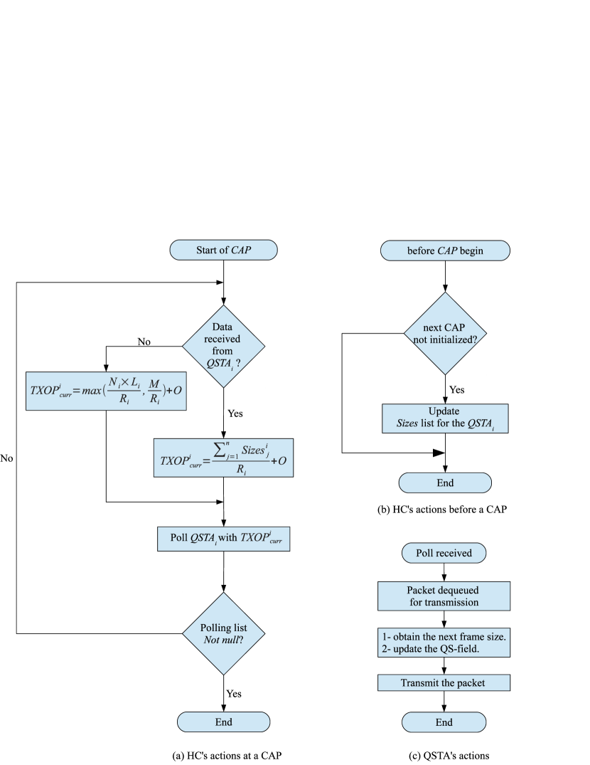
At the beginning of each CAP, HC goes through the list and computes for the according to one the these cases: first case is when a data packet is received from the in the previous CAP/SI period, the MSDU size () of the next frame is obtained from the QS field of IEEE 802.11e MAC header. Then, a of is calculated using Equation (6). In other words, the TXOP in is scheduled based on the information received by QAP/HC during , as depicted in Figure 3.
| (6) |
The other case is when no data packet is received due to loss, the QAP will use the Equation (4) of HCCA scheduler to compute the . It is worth noting that at the first CAP of any TS, the TXOP is calculated based on Equation (4) because no information about the next packet size has been reported yet.
4 Performance Evaluation
In order to evaluate the performance of the proposed scheduler, we have used a network simulation tool. The simulation environment setup, and video traffic used as uplink traffics is described in details in this section. The performance of our scheduler is compared against the HCCA. The results of end-to-end delay and throughput are also discussed.
4.1 Simulation Setup
The proposed scheduler has been implemented in the well-known network simulator (ns-2) [17] version 2.27. The HCCA implementation framework ns2hcca [18] has been patched to provide the controlled access mode of IEEE 802.11e functions, HCCA. The ns-2 Traffic Trace [19] agent is used for video stream generation.
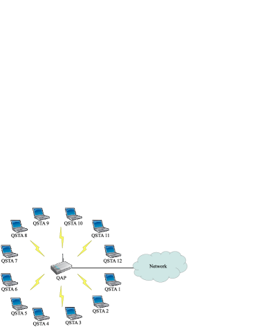
A star topology has been used for constructing the simulation scenario to form an infrastructure network with one QAP surrounded by varying number of the QSTAs ranging from 1 to 12. All QSTAs were distributed uniformly around the QAP with a radius of 10 meters as shown in Figure 5. The stations were placed within the QAP coverage area, in the same basic service set The Basic Service Set (BSS), and the wireless channel is assumed to be ideal. Since we focus on HCCA performance measurement, all the stations operate only on the contention-free mode by setting in Equation (5) to zero.
QAP is the sink receiver, while all stations are the video sources. Each send only an uplink video traffic as only one flow per station is supported in ns2hcca patch. Therefore, for simulating concurrent video streams multiple stations are added each with one flow. In order to leave an ample time for initialization, stations start their transmission after 20 (sec) from the start of the simulation time and last until the simulation end. Wireless channel assumed to be an error-free, and no admission control used for the sake of investigating the maximum scheduling capability of each examined algorithm under heavy traffic conditions. Simulation parameters are summarized in Table 2.
| Parameter | Value |
|---|---|
| Simulation time | 500 (sec) |
| Physical layer | IEEE 802.11b |
| MAC layer | IEEE 802.11e |
| SIFS | 10 |
| PIFS | 30 |
| Slot time | 20 |
| Physical preamble length | 18 (bytes) |
| PLCP header length | 6 (bytes) |
| PLCP data rate | 1 (Mbps) |
| MAC header size | 36 (bytes) |
| Data rate | 11 (Mbps) |
| Basic physical rate | 1 (Mbps) |
For evaluating the performance of our scheduling algorithm against the reference scheduler of HCCA, Jurassic Park 1 video sequence trace encoded using MPEG–4 was chosen from a publicly available library for video traces [7]. We tested the proposed scheduler on Jurassic Park 1 and Formula 1 trace files which can be classified into movie and sport, respectively, which show different variability level. Table 3 demonstrates some statistics of the examined traces. The selected video is encoded using different Compression ratio, which results in varying quality.
| Video Quality | |||
| Video | Parameter | Low quality | High quality |
| Jurassic Park 1 | Comp. ratio (YUV:MP4) | 49.46 | 9.92 |
| Mean size (byte) | 7.7e+02 | 3.8e+03 | |
| CoV of frame size | 1.39 | 0.59 | |
| Mean bit rate (bit/sec) | 1.5e+05 | 7.7e+05 | |
| Peak bit rate (bit/sec) | 1.6e+06 | 3.3e+06 | |
| Peak/Mean of bit rate | 10.61 | 4.37 | |
| Formula 1 | Comp. ratio (YUV:MP4) | 43.51 | 9.92 |
| Mean size (byte) | 8.7e+02 | 4.2e+03 | |
| CoV of frame size | 1.12 | 0.42 | |
| Mean bit rate (bit/sec) | 1.7e+05 | 8.4e+05 | |
| Peak bit rate (bit/sec) | 1.4e+06 | 2.9e+06 | |
| Peak/Mean of bit rate | 8.05 | 3.45 | |
In this paper, we have tested the schedulers with low and high quality video trace. It is worth noting that the variability of the selected videos is measured by the Coefficient of Variation (CoV), which is the standard deviation of the frame size divided by the average frame size. TSPEC parameters used for each video traffic is shown in Table 4 with regards to video QoS requirements.
| Video Quality | |||
| Video | Parameter | Low quality | High quality |
| Jurassic Park 1 | (bytes) | 7.7e+02 | 3.8e+03 |
| (bytes) | 8154 | 16745 | |
| (bit/sec) | 1.5e+05 | 7.7e+05 | |
| (sec) | 0.08 | 0.08 | |
| (Mbps) | 11 | 11 | |
| (sec) | 0.04 | 0.04 | |
| Formula 1 | (bytes) | 8.7e+02 | 4.2e+03 |
| (bytes) | 7032 | 14431 | |
| (bit/sec) | 1.7e+05 | 8.4e+05 | |
| (sec) | 0.08 | 0.08 | |
| (Mbps) | 11 | 11 | |
| (sec) | 0.04 | 0.04 | |
4.2 Results and Discussion
Simulations have been carried out to exhibit the performance of the examined schedulers using a different variability level of the same videos. Since the main objective is to achieve superior QoS support by accurately granting TXOP to the station to fit its need, packet end-to-end delay of the uplink traffics has been measured which considered as one of the significant metrics to evaluate a QoS support of video streams. To validate the behavior of the examined schedulers, the measurements are done for an increasing number of TSs. The system throughput was also investigated to verify that the improvement in the delay is achieved without jeopardizing the channel bandwidth.
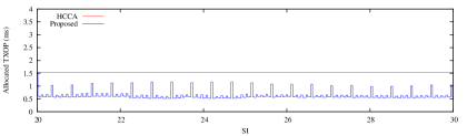
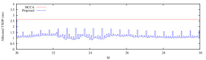
The behavior of the examined schedulers in terms of allocating TXOP in each SI is illustrated in Figure 6 for the Formula 1 video sequence. The allocated TXOP for one flow is shown against number of SIs for a duration of 10 seconds. The results reveal the fact of assigning fixed TXOP in HCCA for all SIs of the flow with accordance to Equation (4). In this case, the HCCA computes TXOP duration based on the maximum MSDU size of the flow, namely 7032 bytes and 14431 bytes for low and high quality video respectively. Nevertheless, the proposed scheduler adaptively allocates a TXOPs for each SI based on the actual frame size obtained from the feedback information which show that in some SIs the allocated TXOP duration in HCCA is much higher than the actual need of the flow which considered as over-allocation cases. It is obvious that the TXOP duration given in 6(b) is higher than that in 6(a) as the mean bit rate of high quality encoded Formula 1 is considerably higher than that in low quality video sequence, refer to Table 3.
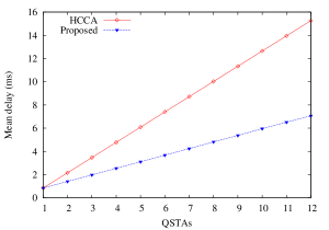
4.2.1 End-to-End Delay Analysis
The end-to-end delay is defined as the time elapsed from the generation of the packet at the source QSTA application layer until it has been received at the QAP and is expressed in Equation (7).
| (7) |
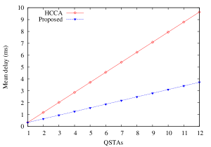
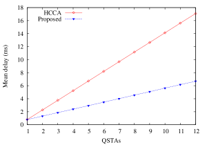
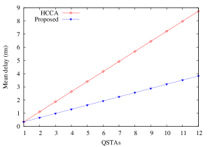
where is the generation time of packet at the source QSTA, is the receiving time of the particular packet at the MAC layer of the QAP, and is the total number of packets for all flows in the system. The end-to-end delay has been measured for the three video types to study the efficiency of both HCCA and our schedulers with different traffic variability. Figure 7(a), 7(b) and 7(c), 7(d) depict the delay experienced by data packets for the low, medium and high quality video, respectively. One can notice that the end-to-end delay boosts with the increase of the packet size, higher quality exhibit higher end-to-end delay and vice versa. The increase of the delay in higher quality videos can be justified by the large amount of the allocated to each TS, as in Equation (4), which leads to maximize the wasted TXOPs that keep the subsequent TSs awaiting in their transmission queue longer time. It is worth noting that the proposed scheduler achieved about 52% and 46% delay improvement over HCCA for Jurassic Park 1 and Formula 1 respectively. The reason of achieving better improvement in Jurassic Park 1 is the higher packet size comparable to that in Formula 1 thereby the granted TXOP obtained in HCCA is far from the needed TXOP which in turn causes higher packet delay. Furthermore, the delay improvement in our scheduler is justified by the accurate calculation of the TXOP. Unlike the HCCA scheduler that only relies on the mean traffic characteristic which is not reflecting the actual traffic behavior.
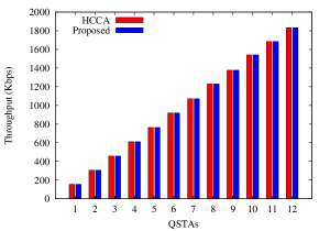
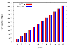
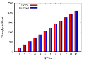
4.2.2 Throughput Analysis
The aggregate throughput of the examined schedulers has been investigated against the number of stations. This is to verify that our scheduler is efficient in supporting QoS for VBR traffics which maintaining the utilization of the channel bandwidth. The aggregate throughput is calculated using Equation (8).
| (8) |
where is the received packet size at the QAP, is the simulation time and is the total number of the received packets at QAP during the simulation time. Figure 8(a), 8(b), 8(c) and 8(d) depict the aggregate throughput with increasing the network load for the low-, medium- and high-quality Jurassic Park 1 videos, respectively. The results show that the throughput is the same as that achieved by the HCCA scheduling scheduler. This implies that our approach enhanced the end-to-delay without jeopardizing the channel bandwidth.

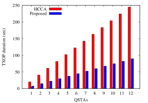
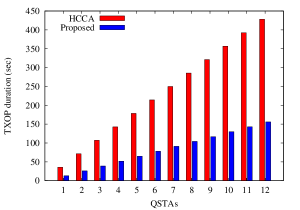
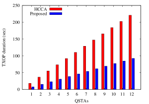
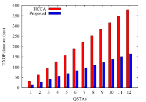
4.2.3 Aggregate TXOP Duration
To investigate the efficiency attained by the proposed scheduler in supporting prerecorded videos against HCCA, the aggregate TXOP duration is measured and can be defined as the total of TXOP duration granted to all QSTAs for the simulation time in units of seconds. In Figure 9, the aggregate TXOP is shown in the examined videos with increasing the network load. For Low-quality videos Figures 9(a) and 9(c) demonstrate that allocating fixed TXOP for all TS frames in HCCA might exceed the need of the traffic. In that case only a small portion of the granted TXOP is exploited resulting in what’s called wasted TXOPs. On the contrary, the proposed scheduler operates according to the actual information about frame size, the granted TXOP is considerably smaller than that in HCCA without jeopardizing the throughput. This fact is more obvious when transmitting High-quality videos (Figures 9(b) and 9(d)) where the wasted TXOP is much higher. It is worth mentioning that Jurassic Park 1 shows higher wasted TXOP than that in Formula 1 as the CoV is higher.
5 Conclusion
This study proposed a novel scheduling scheduler to support VBR video streams in IEEE 802.11e WLANs. This scheduler dynamically assigns TXOP to a QSTA based on piggybacked information about the next frame size with each packet sent of uplink traffic instead of assigning fixed TXOP of HCCA. Accordingly, HC is able to poll QSTAs with regard to their fast changing in the traffic profile so as to prevent QSTAs from receiving unnecessary large TXOP which produces a remarkable increase in the packet delay. The proposed scheduler has been evaluated over two video streams with varying quality level to verify the performance of supporting videos with low and high variability traffics. Simulation results reveal the efficiency of the proposed scheduler over HCCA in terms of minimizing the end-to-end delay while maintaining the system throughput and enhance the channel bandwidth utilization as well.
Acknowledgements
This research work was supported by the Malaysian Ministry of Education under the Fundamental Research Grant Scheme, FRGS/1/2014/ICT03/UPM/01/1
References
- [1] IEEE 802.11 standard. IEEE Standard for Information Technology- Telecommunications and Information Exchange Between Systems- Local and Metropolitan Area Networks- Specific Requirements- Part 11: Wireless LAN Medium Access Control (MAC) and Physical Layer (PHY) Specifications, 1999.
- [2] IEEE 802.11e standard. IEEE Standard for Information Technology - Telecommunications and Information Exchange Between Systems - Local and Metropolitan Area Networks - Specific Requirements - Part 11: Wireless LAN Medium Access Control (MAC) and Physical Layer (PHY) Specifications, 2007.
- [3] IEEE 802.11e standard. IEEE Standard for Information technology–Telecommunications and information exchange between systems local and metropolitan area networks–Specific requirements part 11: Wireless LAN Medium Access Control (MAC) and Physical Layer (PHY) Specifications. IEEE Std 802.11-2012 (Revision of IEEE Std 802.11-2007), pages 1–2793, March 2012.
- [4] ITU-T. ITU-T Recommendation G.711. Pulse Code Modulation (PCM) of Voice Frequencies, 1988.
- [5] T. Sikora. MPEG Digital Video-Coding Standards. IEEE Signal Processing Magazine, 14(5):82–100, 1997.
- [6] Nitin Narang. Digital Media Convergence: Are the Stakeholders Listening? IT Matters, page 21, 2012.
- [7] F.H.P. Fitzek and M. Reisslein. MPEG–4 and H.263 Video Traces for Network Performance Evaluation. IEEE Network, 15(6):40–54, 2001.
- [8] F. Fitzek. and M. Reisslein. MPEG-4 and H.263 Video Traces for Network Performance Evaluation. Technical Report TKN-00-006, Telecommunication Networks Group, Technische Universität Berlin, 2000.
- [9] Luis Ducla Soares and Fernando Pereira. MPEG-4: A Flexible Coding Standard for the Emerging Mobile Multimedia applications. In Personal, Indoor and Mobile Radio Communications, 1998. The Ninth IEEE International Symposium on, volume 3, pages 1335–1339, 1998.
- [10] Rob Koenen. MPEG-4 Multimedia for our Time. Spectrum, IEEE, 36(2):26–33, 1999.
- [11] Rob Koenen. Overview of the MPEG-4 Standard. ISO/IEC JTC1/SC29/WG11 N, 1730:11–13, 2002.
- [12] Dong-Yul Lee, Sung-Ryun Kim, and Chae-Woo Lee. An Enhanced EDD QoS Scheduler for IEEE 802.11e WLAN. In Advances in Computational Science and Engineering, volume 28 of Communications in Computer and Information Science, pages 45–59. Springer Berlin Heidelberg, 2009.
- [13] Aphirak Jansang and Anan Phonphoem. Adjustable TXOP mechanism for supporting video transmission in IEEE 802.11e HCCA. EURASIP Journal on Wireless Communications and Networking, 2011(1):1–16, 2011.
- [14] G. Cecchetti, A.L. Ruscelli, A. Mastropaolo, and G. Lipari. Providing Variable TXOP for IEEE 802.11e HCCA Real-Time Networks. In Wireless Communications and Networking Conference (WCNC), pages 1508–1513, 2012.
- [15] Gabriele Cecchetti, Anna Lina Ruscelli, Antonia Mastropaolo, and Giuseppe Lipari. Dynamic TXOP HCCA Reclaiming Scheduler with Transmission Time Estimation for IEEE 802.11e Real-Time Networks. In Proceedings of the 15th ACM international conference on Modeling, analysis and simulation of wireless and mobile systems, pages 239–246. ACM, 2012.
- [16] Anna Lina Ruscelli, Gabriele Cecchetti, Angelo Alifano, and Giuseppe Lipari. Enhancement of QoS support of HCCA schedulers using EDCA function in IEEE 802.11e networks. Ad Hoc Networks, 10(2):147 – 161, 2012.
- [17] Steven McCanne and Sally Floyd. NS network simulator, 1995.
- [18] Claudio Cicconetti, Luciano Lenzini, Enzo Mingozzi, and Giovanni Stea. A software architecture for simulating IEEE 802.11e HCCA. In IPS-MoMe05: Proceeding from the 3rd Workshop on Internet Performance, Simulation, Monitoring and Measurement, pages 97–104, 2005.
- [19] Teerawat Issariyakul and Ekram Hossain. Introduction to Network Simulator NS2. Springer, 2012.