Locally Rewritable Codes for Resistive Memories
Abstract
We propose locally rewritable codes (LWC) for resistive memories inspired by locally repairable codes (LRC) for distributed storage systems. Small values of repair locality of LRC enable fast repair of a single failed node since the lost data in the failed node can be recovered by accessing only a small fraction of other nodes. By using rewriting locality, LWC can improve endurance limit and power consumption which are major challenges for resistive memories. We point out the duality between LRC and LWC, which indicates that existing construction methods of LRC can be applied to construct LWC.
I Introduction
In the big data era, coding for storage systems has become more important than before. Recently, coding for distributed storage systems has become an attractive research area at the (higher) system level. In addition, coding for nonvolatile memories and hard disk drives (HDD) is also important to achieve high-density storage systems at the (lower) physical level.
An important group of codes for distributed storage system is locally repairable (or recoverable) codes (LRC) [1, 2]. An LRC is a code of length with information (message) length , minimum distance , and repair locality . If a symbol in the LRC-coded data is lost due to a node failure, its value can be repaired (i.e. reconstructed) by accessing at most other symbols [2, 3].
One way to ensure fast repair is to use low repair locality such that at the cost of minimum distance . The relation between and is given by [2]
| (1) |
It is worth mentioning that this bound is a generalization of the Singleton bound. The LRC achieving this bound with equality are called optimal. Constructions of the optimal LRC were proposed in [4, 3, 5]. Recently, several binary LRC constructions have been proposed [6, 7, 8, 9, 10].
At the lower (physical) level, coding for nonvolatile memories is an active research area since nonvolatile memories including flash memories and resistive memories are important parts of mobile devices and solid state drives (SSD).
In this paper, we investigate coding for resistive memories including phase change memories (PCM) and resistive random-access memories (RRAM). Resistive memory technologies are promising since they are expected to offer higher density than dynamic random-access memories (DRAM) and better speed performance than NAND flash memories [11].
The major challenges of resistive memories are endurance limit and power consumption [12, 13]. Endurance limit refers to the maximum number of writings that the memory can endure. In order to improve endurance and power consumption of such memories, we propose locally rewritable codes (LWC).111LWC instead of LRC is used as the acronym of locally rewritable codes in order to distinguish them from locally repairable codes (LRC). Inspired by the repair locality defined for distributed storage systems, we introduce the rewriting locality which improves power consumption and endurance limit. In addition, we show the duality between LRC and LWC, which indicates that existing construction methods of LRC can be used to construct LWC.
The rest of this paper is organized as follows. Section II explains the basics and challenges of resistive memories. Section III presents the notation and the defect channel model for resistive memories. In Section IV, we propose LWC and explain the duality of LRC and LWC. In Section V, we will discuss the future work and conclude the paper.
II Resistive Memories
PCM and RRAM are two major types of resistive memories. Both have attracted significant research interest due to their scalability, compactness, and simplicity. The main challenges that prevent their large-scale deployment are endurance limit and power consumption [12, 13]. The endurance limit refers to the maximum number of writes before the memory becomes unreliable. As explained in following subsections, the resistive memory cells have the limited endurance. Beyond this number, these cells can become stuck-at defects. In addition, the power consumption depends on the number of writes.
II-A Phase Change Memories (PCM)
PCM consists of chalcogenide materials like Ge-Sb-Te (GST), which are known to have two stable resistance states [12]. As shown in Fig. 1, the low resistance state (LRS) corresponds to a crystalline structure of the chalcogenide material, whereas the high resistance state (HRS) corresponds to an amorphous structure. The transition from HRS to LRS, known as SET, is brought about by applying a long and low-power heat pulse to the device by the means of a heating element. Similarly, the transition from LRS to HRS, or RESET, is brought about by pulsing the device with a short and high-power heat pulse that melts the chalcogenide, thus amorphizing it. Both operations can be done on the nanosecond time scale. However, the elapsed time for SET operation could be up to ten times of RESET operation [12, 14].

PCM has shown great promise as a storage-class memory due to its superior resistance ratio, scalability, low-energy switching, and high-speed [15, 14]. However, one of the main challenges for PCM is its endurance limit. From the point of view of the data, this corresponds to stuck-at defects (or stuck-at faults). Such defects may either appear in as-fabricated devices due to process variations or may be generated during the cycling process, i.e., rewriting.
The stuck-at defects in PCM are classified into: (1) stuck-at LRS defect which corresponds to the device in LRS being unable to RESET to HRS; and (2) stuck-at HRS defect which corresponds to the device in HRS incapable of being SET to LRS for the same operating conditions [16]. The stuck-at LRS defect is traditionally attributed to the formation of crystallites in the amorphous state that do not melt (during the amorphization pulse) due to local inhomogeneities [17]. This causes the HRS to gradually move towards the LRS with cycling. Similarly, the stuck-at HRS is attributed to the formation of voids in the materials and their eventual agglomeration [18]. This causes the material to experience an inhomogeneous and often insufficient heating during the SET operation.
II-B Resistive Random-Access Memories (RRAM)
RRAM is another resistance change memory that relies on microstructural change in the material that causes the cell to have two resistance states (LRS and HRS). As shown in Fig. 2, the RRAM cell consists of a metal-oxide-metal (MOM) stack in which the sub-oxide is typically , or . The devices do not start off as being resistive switching memories; they have to go through a one-time programming process known as forming. The forming process involves the application of a high voltage pulse that causes the oxide to breakdown and form a conductive filament that shunts the two metal electrodes, causing the resistance to decrease [19]. The LRS corresponds to the shunted conductive filament. This filament can be disconnected by applying a voltage of the opposite polarity. Once the conductive filament is disconnected, the device resistance increases, and the device is said to be in the HRS. The device can now be cycled between LRS and HRS by applying voltages of opposite polarity as shown in Fig. 2.
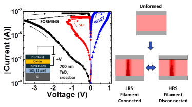
As the RRAM switching mechanism is filamentary in nature, the RRAM devices are highly scalable, operate at ultra-low powers, have good retention characteristics, and can be integrated into a compact crossbar array [13].
However, similar to PCM, RRAM also suffers from limited endurance, especially when operated at low power [20]. In RRAM, the stuck-at defects may be additionally introduced during the forming process due to poor power-limiting during the breakdown [19].
The stuck-at LRS defects in RRAM have been attributed to the widening of the conductive filament [21]. Once the filament widens, the device resistance drops and the RESET power is insufficient to disconnect the filament. This causes the cell to be permanently set to LRS. The widening of the filament is thought of as a stochastic increase in the number of oxygen vacancies in the filament during the SET and forming operation. It can be explained by an incomplete retraction of oxygen vacancies during the previous RESET [22]. Similarly, the devices can also suffer from a stuck-at-HRS defect if the devices undergo over-RESET [23]. In this process, the oxygen vacancies are retracted irreversibly, making the device stuck-at HRS defect.
Similar to PCM, once the device starts experiencing the over-SET or over-RESET which precedes endurance failure, the devices would undergo a positive feedback that would make the stuck-at defects imminent. Moreover, as the endurance failure is mediated by stochastic motion of oxygen vacancies during the SET or RESET processes [24], it is very difficult to prevent these stuck-at defects.
III Channel Model
In Section II, we explained that both PCM and RRAM suffer from stuck-at HRS or LRS defects. The resistance state can be sensed as either 0 or 1, depending on the sensing scheme of read operation (e.g., HRS 0, LRS 1 or vice versa). Thus, we can claim that the defect channel model by Kuznetsov and Tsybakov [25] is a proper mathematical model for resistive memories. After providing notation, we will explain the defect channel model.
III-A Notation
We use parentheses to construct column vectors from comma separated lists. For a -tuple column vector (where denotes the finite field with elements and denotes the set of all -tuple vectors over ), we have
| (2) |
where superscript denotes transpose. Note that represents the -th element of . For a binary vector , denotes the bit-wise complement of . For example, the -tuple all-ones vector is equal to where is the -tuple all-zero vector. Also, denotes the all-zero matrix.
In addition, denotes the Hamming weight of and denotes the support of . We use the notation of for and . Note that and .
III-B Channel Model: Defect Channel
We summarize the defect channel model in [25]. Define a variable that indicates whether the memory cell is defective or not and . Let “” denote the operator as in [26]
| (3) |
By using the operator , an -cell memory with defects is modeled by
| (4) |
where are the channel input and output vectors. Also, the channel state vector represents the defect information in the -cell memory. Note that is the vector component-wise operator.
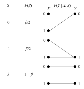
If , this -th cell is called normal. If the -th cell is defective (i.e., ), its output is stuck-at independent of the input . So, the -th cell is called stuck-at defect whose stuck-at value is . The probabilities of stuck-at defects and normal cells are given by
| (5) |
where the probability of stuck-at defects is . Fig. 3 shows the binary defect channel for .
IV Locally Rewritable Codes (LWC)
IV-A Motivation and Toy Example
As a toy example, suppose that -cell binary memory has a single stuck-at defect. It is easy to see that this stuck-at defect can be handled by the following simple technique [25].
| (6) |
where is a codeword and is an information (message) where and is a parity (redundant) bit.
Suppose that -th cell is a defect whose stuck-at value is . If and , or if and , then should be 0. Otherwise, . Thus, decides whether to flip or not. It is worth mentioning that this simple coding is optimal since it achieves the following upper bound in [25] with equality.
| (7) |
where is the number of codewords and is the number of stuck-at defects among cells. For linear codes, , i.e., .
If there is no stuck-at defect among cells, then we can store by writing (i.e., ). Now, consider the case when stored information needs to be updated causing to become . Usually, , which happens often due to the updates of files. Instead of storing into another group of cells, it is more efficient to store by rewriting only cells. For example, suppose that for an and for all other . Then, we can store -bit by rewriting only -th cell.
An interesting problem arises when a cell to be rewritten is defective. Suppose that -th cell is a stuck-at defect whose stuck-at value is . If , then we should write for storing . However, in order to store the updated information , we should write where . Thus, cells should be rewritten to update one bit data without stuck-at error. The same thing happens when . When considering endurance limit and power consumption, rewriting cells is a high price to pay for preventing one bit stuck-at error.
In order to relieve this burden, we change (6) by introducing an additional parity bit as follows.
| (8) | ||||
| (9) |
where . For simplicity’s sake, we assume that is even. Then, and are all-ones and all-zeros column vectors with elements. By introducing an additional parity bit, we can reduce the number of rewriting cells from to .
This idea is similar to the concept of Pyramid codes which are the early LRC [1]. For disk nodes, single parity check codes can repair one node failure (i.e., single erasure) by
| (10) |
where represents the recovered codeword from disk node failures. Assuming that is erased due to a node failure, can be recovered by
| (11) |
For this recovery, we should access nodes which degrades the repair speed. For more efficient repair process, we can add a new parity as follows.
| (12) |
Then, a failed node can be repaired by accessing only nodes. Note that the repair locality of (12) is whereas the repair locality of (10) is which is a simple but effecitve idea of Pyramid codes.
IV-B Locally Rewritable Codes
In this subsection, we propose LWC by generalizing the idea of the toy example in the previous subsection. A traditional coding scheme for defect channel is additive encoding which masks defects by adding a carefully selected vector. The goal of masking stuck-at defects is to make a codeword whose values at the locations of defects match the stuck-at values of corresponding defects [25, 28]. The additive encoding can be formulated as
| (13) |
where . By adding a vector , we can mask stuck-at defects among cells. For the systematic codes, is given by [26]
| (14) |
where and is the -dimensional identity matrix. Note that the identity matrix is located in the parity part unlike the conventional error-control codes.
The decoding can be given by
| (15) |
where represents the recovered message of . Note that the parity check matrix of is given by and . Note that (15) is equivalent to the equation of coset codes.
The minimum distance of additive encoding is given by
| (16) |
which means that any rows of are linearly independent. Thus, additive encoding guarantees masking up to stuck-at defects [28, 26].
Now we investigate rewriting locality of additive encoding. As repair locality of LRC is meaningful only for single disk failure, rewriting locality is valid when there is one stuck-at defect among cells. In distributed storage systems, the most common case is a single node failure among nodes [1]. Similarly, for a proper defect probability , we can claim that the most common scenario of resistive memories is that there is a single stuck-at defect among cells.
We define initial writing cost and rewriting cost which are related to write endurance and power consumption.
Definition 1 (Initial Writing Cost)
Suppose that was stored by its codeword in the initial stage of cells where all the normal cells are set to zeros. The writing cost is given by
| (17) |
where denotes the number of stuck-at defects whose stuck-at values are nonzero.
In (17), we assume that there are stuck-at defects among cells and masks these stuck-at defects successfully. So, we do not need to write stuck-at defects since their stuck-at values are the same as corresponding elements of .
Definition 2 (Rewriting Cost)
Suppose that was stored by its codeword in cells. If is rewritten to these cells to store the updated , the rewriting cost is given by
| (18) |
where we assume that both and mask stuck-at defects.
High rewriting cost implies that the states of lots of cells should be changed, which is harmful to write endurance and increases power consumption.
It is worth mentioning that, in general, the rewriting cost is more important than the initial writing cost since most of write operations will be rewriting. If a device offers write endurance of 10000 cycles, the write operations of 9999 will be rewriting whereas only one among 10000 writing is the initial write operation (i.e., 0.01%). However, there may be some storage applications (such as for archival storage), where the number of initial writings and rewritings may be similar.
Now, we introduce the rewriting locality which affects initial writing cost and rewriting cost.
Definition 3 (Information Rewriting Locality)
Suppose that for , i.e., information (message) part, should be updated to and the corresponding -th cell is a stuck-at defect. If can be updated to by rewriting other cells, then the -th coordinate has information rewriting locality .
Lemma 4
If the -th coordinate for has information rewriting locality , then there exists such that and .
Proof:
For and , suppose that for an and for all other . Note that -th cell is a stuck-at defect whose stuck-at value is . We should consider the following cases:
-
1.
.
-
2.
.
-
3.
, and .
For , it is obvious that and where by (13). For the information rewriting locality , should satisfy to mask the stuck-at defect by writing cells. Note that we do not need to write the stuck-at defect since its stuck-at value is . For , the proof is similar.
For , and , and . We can pick and such that (where ) and . For the information rewriting locality , and should satisfy . ∎
Definition 5 (Parity Rewriting Locality)
Suppose that only one nonzero symbol should be stored to the initial stage of cells. Note that there is a stuck-at defect in the parity location for (i.e., parity part) and . If can be stored by writing at most cells, then the -th coordinate has parity rewriting locality .
Lemma 6
If the -th coordinate for has parity rewriting locality , then there exists such that and .
Proof:
Suppose that should be stored to the initial stage of cells where for and for . By (13), such that where the -th cell is a stuck-at defect for . For the parity rewriting locality , should satisfy . If , then it is possible to store without stuck-at error by writing cells since we do not need to write . Otherwise, we should write both and , i.e., cells. ∎
Definition 7 (Locally Rewritable Codes)
If any -th coordinate for has (information or parity) rewriting locality at most , then this code is called locally rewritable code (LWC) with rewriting locality . LWC code is a code of length with information length , minimum distance , and rewriting locality .
Now, we show in the following theorem that rewriting locality is an important parameter for rewriting cost.
Theorem 8
Suppose that is updated to by LWC with rewriting locality . If there is a single stuck-at defect in cells, then the rewriting cost is given by
| (19) |
Proof:
First, suppose that the single defect’s coordinate is and its stuck-at value is . If , then since and where .
If , then and where . In order to mask the stuck-at defect, . Then,
| (20) | ||||
| (21) | ||||
| (22) | ||||
| (23) |
where (22) follows from the where is the -th element of . Also, (23) follows from Lemma 4. By supposing for and for , i.e., , we confirm that the RHS of (23) is , which coincides with Definition 3. For , we can show (19) by a similar method.
Next, suppse that the single defect’s coordinate is . Since and , the rewriting cost is . ∎
Corollary 9
If is stored in the initial stage of cells with a single stuck-at defect, then the writing cost is given by
| (24) |
Proof:
First suppose that the single defect’s coordinate is and its stuck-at value is . If , then . The writing cost .
Next suppose that the single defect’s coordinate is . If , then . If , then where . By Lemma 6, we can claim that . ∎
IV-C Duality of LRC and LWC
In this subsection, we investigate the duality of LRC and LWC. We show that existing construction methods of LRC can be used to construct LWC based on this duality. First, the relation between minimum distance and rewriting locality is observed.
Definition 10
If is cyclic, then the LWC is called cyclic.
Lemma 11
Let denote a cyclic code whose minimum distance is . Then, corresponding cyclic LWC’s rewriting locality is .
Proof:
Due to the property of cyclic codes, we can claim that there exists such that and for any . Since is the minimum distance of , we can claim that the rewriting locality is . ∎
From the definition of in (16), which is the minimum distance of , namely, dual code of . Thus, the parameters of cyclic LWC is given by
| (28) |
In [8, 9], an equivalent relation for cyclic LRC was given by
| (29) |
By comparing (28) and (29), we observed the duality between LRC and LWC. This duality is important since it indicates that we can construct LWC using existing construction methods of LRC as shown in the following theorem.
Theorem 12
Suppose that is the parity check matrix of cyclic LRC with . By setting , we can construct cyclic LWC with
| (30) |
Proof:
Remark 13 (Optimal Cyclic LWC)
Theorem 12 shows that the optimal cyclic LRC can be used to construct the optimal cylic LWC such that
| (32) |
Hence, the optimal LWC can be constructed from the optimal LRC.
Remark 14 (Bound of LWC)
| LRC | LWC | |
|---|---|---|
| Application | Distributed storage systems | Resistive memories |
| (system level) | (physical level) | |
| Channel | Erasure channel | Defect channel |
| Encoding | ||
| Decoding | ||
| Bound | ||
| Trade-off | (reliability) vs. | (reliability) vs. |
| (repair efficiency) | (rewriting cost) |
In Table I, the duality properties of LRC and LWC are summarized. In the decoding of LRC, denotes a recovered codeword from node failures. In addition, in the decoding of LWC represents the recovered message. It is worth mentioning that this duality can be connected to the duality between erasures and defects [29].
V Conclusion and Future Work
Inspired by LRC for distributed storage systems, we proposed LWC to improve endurance limit and power consumption of resistive memories. We showed the relation between rewriting cost and rewriting locality of LWC. Also, we investigated the duality between LRC and LWC, which makes it possible to construct LWC by using existing construction methods of LRC.
As part of our future work, we plan to evaluate the performance of LWC. Although some recent works have investigated the characteristics of endurance limit [20, 24], a proper channel model is not available.222Fig. 4 in [20] shows that the relation between the endurance and the probability of stuck-at defects might be modeled by the lognormal distribution. However, only 25 cells were observed, which would not be enough to characterize the channel model. Hence, the performance evaluation would need to be based on the experiments with real resistive memory chips.
References
- [1] C. Huang, M. Chen, and J. Li, “Pyramid codes: Flexible schemes to trade space for access efficiency in reliable data storage systems,” in Proc. IEEE Int. Symp. Netw. Comput. Appl. (NCA), Jul. 2007, pp. 79–86.
- [2] P. Gopalan, C. Huang, H. Simitci, and S. Yekhanin, “On the locality of codeword symbols,” IEEE Trans. Inf. Theory, vol. 58, no. 11, pp. 6925–6934, Nov. 2012.
- [3] I. Tamo and A. Barg, “A family of optimal locally recoverable codes,” IEEE Trans. Inf. Theory, vol. 60, no. 8, pp. 4661–4676, Aug. 2014.
- [4] N. Silberstein, A. S. Rawat, O. O. Koyluoglu, and S. Vishwanath, “Optimal locally repairable codes via rank-metric codes,” in Proc. IEEE Int. Symp. Inf. Theory (ISIT), Jul. 2013, pp. 1819–1823.
- [5] I. Tamo, D. S. Papailiopoulos, and A. G. Dimakis, “Optimal locally repairable codes and connections to matroid theory,” in Proc. IEEE Int. Symp. Inf. Theory (ISIT), Jul. 2013, pp. 1814–1818.
- [6] S. Goparaju and R. Calderbank, “Binary cyclic codes that are locally repairable,” in Proc. IEEE Int. Symp. Inf. Theory (ISIT), Jul. 2014, pp. 676–680.
- [7] M. Shahabinejad, M. Khabbazian, and M. Ardakani, “An efficient binary locally repairable code for hadoop distributed file system,” IEEE Commun. Lett., vol. 18, no. 8, pp. 1287–1290, Aug. 2014.
- [8] P. Huang, E. Yaakobi, H. Uchikawa, and P. H. Siegel, “Cyclic linear binary locally repairable codes,” in Proc. IEEE Inf. Theory Workshop (ITW), Apr. 2015, pp. 1–5.
- [9] I. Tamo and A. Barg, “Cyclic LRC codes and their subfield subcodes,” in Proc. IEEE Int. Symp. Inf. Theory (ISIT), Jul. 2015, pp. 1262–1266.
- [10] N. Silberstein and A. Zeh, “Optimal binary locally repairable codes via anticodes,” in Proc. IEEE Int. Symp. Inf. Theory (ISIT), Jun. 2015, pp. 1247–1251.
- [11] Intel and Micron, “3D XPoint Technology,” 2015. [Online]. Available: https://www.micron.com/about/innovations/3d-xpoint-technology
- [12] H.-S. P. Wong, S. Raoux, S. Kim, J. Liang, J. P. Reifenberg, B. Rajendran, M. Asheghi, and K. E. Goodson, “Phase change memory,” Proc. IEEE, vol. 98, no. 12, pp. 2201–2227, Dec. 2010.
- [13] H.-S. P. Wong, H.-Y. Lee, S. Yu, Y.-S. Chen, Y. Wu, P.-S. Chen, B. Lee, F. T. Chen, and M.-J. Tsai, “Metal–Oxide RRAM,” Proc. IEEE, vol. 100, no. 6, pp. 1951–1970, Jun. 2012.
- [14] S. Raoux, F. Xiong, M. Wuttig, and E. Pop, “Phase change materials and phase change memory,” MRS Bulletin, vol. 39, pp. 703–710, Aug. 2014.
- [15] S. Raoux, G. W. Burr, M. J. Breitwisch, C. T. Rettner, Y. C. Chen, R. M. Shelby, M. Salinga, D. Krebs, S.-H. Chen, H. L. Lung, and C. H. Lam, “Phase-change random access memory: A scalable technology,” IBM Journal of Research and Development, vol. 52, no. 4.5, pp. 465–479, Jul. 2008.
- [16] S. Kim, P. Y. Du, J. Li, M. Breitwisch, Y. Zhu, S. Mittal, R. Cheek, T.-H. Hsu, M. H. Lee, A. Schrott, S. Raoux, H. Y. Cheng, S.-C. Lai, J. Y. Wu, T. Y. Wang, E. A. Joseph, E. K. Lai, A. Ray, H.-L. Lung, and C. Lam, “Optimization of programming current on endurance of phase change memory,” in Proc. Int. Symp. VLSI Technol., Syst., Appl. (VLSI-TSA), Apr. 2012, pp. 1–2.
- [17] S. Lee, G. Kim, S. Hong, S. J. Baik, H. Hori, and D.-h. Ahn, “Enhanced cycling endurance in phase change memory via electrical control of switching induced atomic migration,” in Proc. 14th Annu. Non-Volatile Memory Techn. Symp. (NVMTS), Oct. 2014, pp. 1–3.
- [18] C.-F. Chen, A. Schrott, M. H. Lee, S. Raoux, Y. H. Shih, M. Breitwisch, F. H. Baumann, E. K. Lai, T. M. Shaw, P. Flaitz, R. Cheek, E. A. Joseph, S.-H. Chen, B. Rajendran, H. L. Lung, and C. Lam, “Endurance improvement of Ge2Sb2Te5-based phase change memory,” in Proc. IEEE Int. Memory Workshop (IMW), May 2009, pp. 1–2.
- [19] A. A. Sharma, M. Noman, M. Abdelmoula, M. Skowronski, and J. A. Bain, “Electronic instabilities leading to electroformation of binary metal oxide-based resistive switches,” Adv. Functional Mater., vol. 24, no. 35, pp. 5522–5529, Jul. 2014.
- [20] Y. Y. Chen, L. Goux, S. Clima, B. Govoreanu, R. Degraeve, G. S. Kar, A. Fantini, G. Groeseneken, D. J. Wouters, and M. Jurczak, “Endurance/retention trade-off on /metal cap 1T1R bipolar RRAM,” IEEE Trans. Electron Devices, vol. 60, no. 3, pp. 1114–1121, Mar. 2013.
- [21] E. Yalon, A. A. Sharma, M. Skowronski, J. A. Bain, D. Ritter, and I. V. Karpov, “Thermometry of filamentary RRAM devices,” IEEE Trans. Electron Devices, vol. 62, no. 9, pp. 2972–2977, Sep. 2015.
- [22] J. Kwon, A. A. Sharma, J. A. Bain, Y. N. Picard, and M. Skowronski, “Oxygen vacancy creation, drift, and aggregation in TiO2-based resistive switches at low temperature and voltage,” Adv. Functional Mater., vol. 25, no. 19, pp. 2876–2883, 2015.
- [23] H. Y. Lee, Y. S. Chen, P. S. Chen, P. Y. Gu, Y. Y. Hsu, S. M. Wang, W. H. Liu, C. H. Tsai, S. S. Sheu, P.-C. Chiang, W. P. Lin, C. H. Lin, W. S. Chen, F. T. Chen, C. H. Lien, and M. Tsai, “Evidence and solution of over-RESET problem for HfO based resistive memory with sub-ns switching speed and high endurance,” in Proc. IEEE Int. Electron Devices Meeting (IEDM), Dec. 2010, pp. 19.7.1–19.7.4.
- [24] C. Y. Chen, L. Goux, A. Fantini, S. Clima, R. Degraeve, A. Redolfi, Y. Y. Chen, G. Groeseneken, and M. Jurczak, “Endurance degradation mechanisms in TiNTa2O5Ta resistive random-access memory cells,” Applied Physics Letters, vol. 106, no. 5, pp. 053 501–1–3, 2015.
- [25] A. V. Kuznetsov and B. S. Tsybakov, “Coding in a memory with defective cells,” Probl. Peredachi Inf., vol. 10, no. 2, pp. 52–60, Apr.–Jun. 1974.
- [26] C. Heegard, “Partitioned linear block codes for computer memory with “stuck-at” defects,” IEEE Trans. Inf. Theory, vol. 29, no. 6, pp. 831–842, Nov. 1983.
- [27] S. I. Gelfand and M. S. Pinsker, “Coding for channel with random parameters,” Probl. Contr. and Inf. Theory, vol. 9, no. 1, pp. 19–31, 1980.
- [28] B. S. Tsybakov, “Additive group codes for defect correction,” Probl. Peredachi Inf., vol. 11, no. 1, pp. 111–113, Jan.–Mar. 1975.
- [29] Y. Kim and B. V. K. Vijaya Kumar, “On the duality of erasures and defects,” arXiv preprint arXiv:1403.1897, vol. abs/1403.1897, 2014. [Online]. Available: http://arxiv.org/abs/1403.1897