Simple fluidic digital half-adder
Abstract
A fluidic one-bit half-adder is made of five channels which intersect at a junction. Two channels are inputs, two channels are outputs and one channel is the drain. The channels direct fluid from input fragments to output fragments and the streams of fluid interact at the junctions. Binary signals are represented by water droplets introduced in the input channels: presence of a droplet in an input or output segments symbolises logical True, absence — False. The droplets travel along channels by following a path of least resistance unless deflected at the junction. We demonstrate the function of the half-adder in both computer modelling and laboratory experiments, and propose a design of a one-bit full adder based on simulation.
a Cardiff School of Engineering, Cardiff University, Cardiff, Wales, UK
b Unconventional Computing Centre, UWE, Bristol, UK
c Laboratory of Artificial Biology, Centre for Integrative Biology, University of Trento, Italy
1 Introduction
Microfluidics provides an ideal environment to precisely control the input parameters of flowing liquids. In this way one can work out in detail the experimental conditions required for the implementation of many different preferred outcomes, including computational logic gates as explored here. Once the ”rules” for computational implementation have been explored in controlled fluidic environments, the droplet technology can then be developed in more complex and real world environments. The implementation of computation with input parameters coming from the natural environment may have impact on future theranostic applications where programmed delivery and controlled release of targeted chemistries would provide a great advance in medical therapies.
Fluids have been used as information carriers and computing substrates since the early 1960s, and this quickly developed into a strong field of science and engineering including a range of high-profile conferences [33, 35]. The advantages of fluidic computing and actuating devices are reliability, tolerances to shock, vibration, radiation, as well as low costs [7, 24]. Fluidic devices, and their modern reincarnations — microfluidic devices, have disseminated through the applied sciences and engineering: aircraft control and actuation, stimuli-responsive gels, cell biology, hydraulics, colloid science, lab-on-a-chip and organ-on-a-chip, enzymatic reactions, non-silicon memory devices, capillary electrophoresis, fuel cells, DNA microarrays, nano-technology, high-throughput biochemical assays [27, 19, 10, 31, 32, 14, 9, 11, 26]. Fluidic devices also found an application in photonics as optofluidic devices and sub-systems [41]: self-assembly techniques and micro fabrication, synthesis of photonics crystals, and optical lab-on-a-chip devices.
Computational fluidic devices must be controlled either by an external computer or through embedded control units. The former is inefficient and the latter requires structural, or physical, programming. The structural programming means encoding of logical values into intensities of fluid pressure or velocity and implementation of logical operations and binary arithmetical circuits at the cascaded junctions where the streams collide. In first five years, since the first ever fluidic logic device was created at the Harry Diamond Lab [7], a number of fluid-based logic elements have been designed. The early logic gates were based on jet/stream attachment, e.g. threshold logic devices [12], and comprised of complex systems of channels with variable width, branching and expansion outlets [22, 17, 40, 30]. With the resurrection of fluidics in the late 1990s, a range of non-trivial devices were implemented including devices for sequential routing of a certain number of droplets to a specified location [37], and addition of droplet volumes via fusion, [36], logic via bubbles in microfluidic channels [34], memory devices with viscous polymer fluids [15], and fluidic transistors that explore the relation between a channel and the electrostatic interactions within the channel [21].
In parallel, and apparently independent to fluidics, the field of collision-based computing [1] emerged in early 1980s. This type of computation is based on the reflection of travelling localisations, which represent values of logical variables. It started with the implementation of functionally complete set (and thus universal computation) with gliders colliding in Conway’s Game of Life cellular automaton [5], conservative logic [13] and billiard ball model [28]. These ideas were further developed into prototypes of collision-based logical gates and circuits implemented with excitation wave-fragments in Belousov-Zhabotinsky medium [2, 8], growing slime mould [3], swarms of soldier crabs [16] and intra-cellular vesicles [29].
Aspiring to merge the above concepts, paradigms and implementations in a very simple, minimalist circuit, we designed, modelled and experimentally implemented a binary micro-fluidic half-adder which implements two logical gates at one junction; namely exclusive disjunction and conjunction.
1.1 Design Concept
The half-adder presented here is based on the principle of fluidic resistance. The flow of fluids through a tube or channel is analogous to that of current along a wire and, as such, there is an equivalent to Ohm’s law. In electronics, Ohm’s law states that voltage is equal to current multiplied by resistance. Similarly in fluidics, the pressure differential along the channel, P, is equal to the volumetric flow rate, Q, multiplied by the fluidic resistance, R.
| (1) |
When considering continuous laminar flow of incompressible liquids in a rectangular channel, the Hagen-Poiseiulle equation can be adapted to give:
| (2) |
where is the average flow velocity of the fluid, is the fluid viscosity, is the channel length and is the hydraulic diameter given by:
| (3) |
with being the cross-sectional area of the channel and the wetting perimeter of the channel. Using these equations, it is possible to calculate the fluidic resistance as:
| (4) |
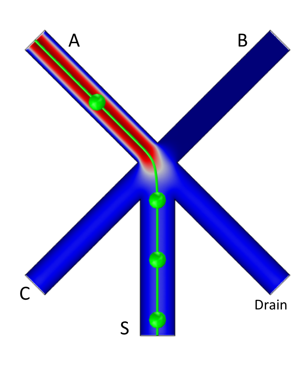
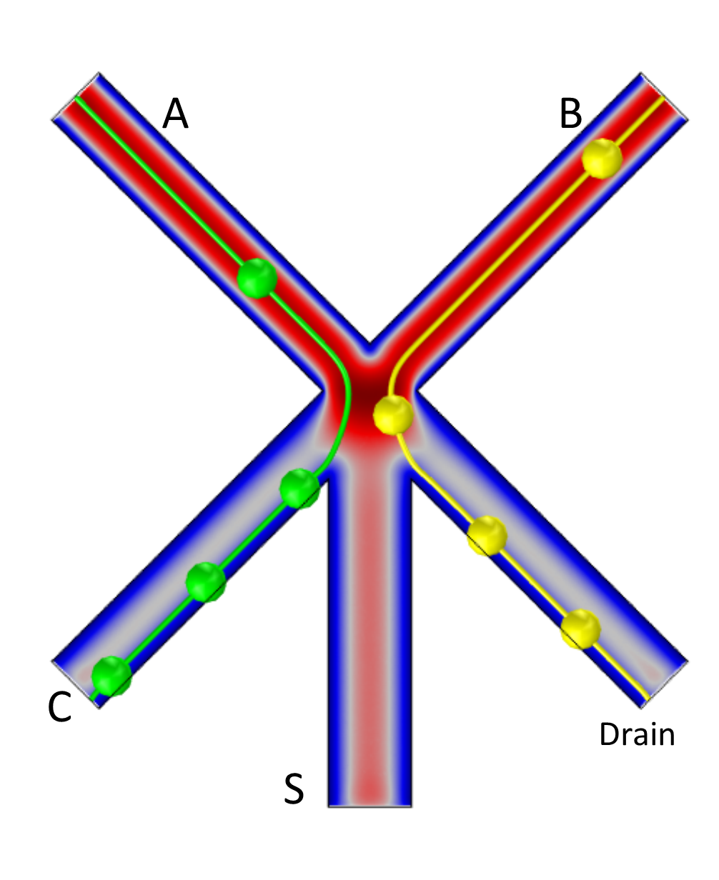
By designing channels of appropriate lengths and diameters it is possible to predict the path a droplet will take through a network of fluidic channels, that being the path of least resistance. The half-adder presented here uses this principle to direct droplets to a given outlet, either by allowing them to travel through the path of least resistance or by actively deflecting them to a different path. The design of the half-adder can be seen in Fig. 1. The droplets arriving at the junction from one of the inputs will preferentially travel down the central channel, representing the sum channel, unless there is also flow from the other input channel. In this case the droplets will travel down the side channels; the carry and drain channels. Droplets that go to the drain outlet are ignored.
2 Materials and Methods
2.1 Microfluidic Device
Microfluidic devices were fabricated by machining 50mm diameter PTFE discs using CNC milling (30,000 rpm, 8mm/s). The PTFE discs were placed within a metal manifold beneath a 100m thick FEP film and a glass window. Finger tight connectors were used to attach tubing to the underside of the manifold and 12 screws were used to apply a compressive force across the glass window to ensure that the fluidic channels were sealed. All channels were milled to a depth of 0.8mm. The sum channel was 1mm wide whilst all other channels were 0.8mm wide. Olive Oil and water were delivered to the device via tubing connected to syringes and driven by syringe pumps. Food colouring was used to dye the water and Oil Red O to dye the oil for illustrative purposes. A True or ’1’ state was created by turning on flow at an input; a False or ’0’ state given by no flow at the input. Droplets were created at a T-junction prior to entering the half-adder junction as indicators of the state.
2.2 Analysis
Flow simulations were performed using COMSOL Multiphysics® using the ’Creeping Flow’ physics module, which solves the Navier Stokes equations for conservation of momentum. Due to the complexity of simulating droplets, requiring large amounts of time or computing power for even simple analysis, the flow was simulated without droplets and streamlines were used to determine the expected path of a droplet. A True (or ’1’) input was represented by an input pressure of 500Pa whilst a False (or ’0’) was simulated as a dead end due to the incompressible nature of fluids. The ’Particle Tracing for Fluid Flow’ module was used to illustrate droplets moving through the device.
3 Results
3.1 Analysis
Initial simulations were undertaken to confirm that flow would be redirected such that the junction would behave as a half adder. The results of these simulations can be seen in Fig. 1, with a single streamline used to represent the path a droplet would take through the junction. If only one of the inputs is True then droplets propagate into the central output channel (Fig. 1a). If both inputs are True then droplets travelling along the input channels are deflected at the junction (Fig. 1b). One droplet enters the left branch and another droplet enters the drain (right branch). These simulations show that output channel implements exclusive disjunction of input variables: and output channel implements conjunction of input variables . That is, the architecture (Fig. 1) implements a binary one-bit half-adder.
3.2 Experimental
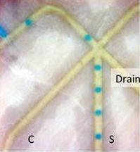

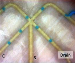
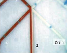
The half adder was tested at a number of different flow rates. The oil flow rate was tested at 8ml/hr and 16ml/hr and the water flow rate was 0.4ml/hr and 1ml/hr (8:0.4, 16:0.4 and 16:1). The junction was found to work for all three flow rate profiles. The results for 16:1 flow rates can be seen in Fig. 2.
4 Discussion
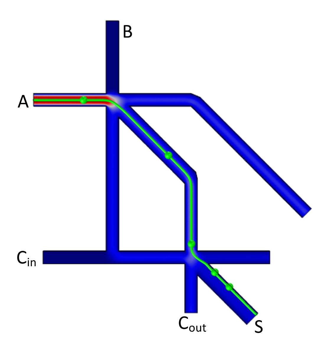
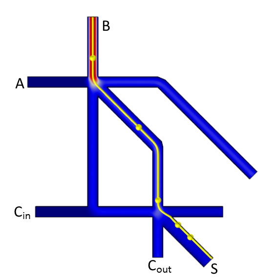
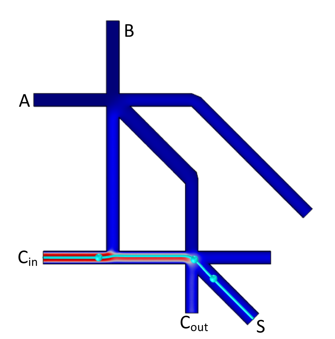
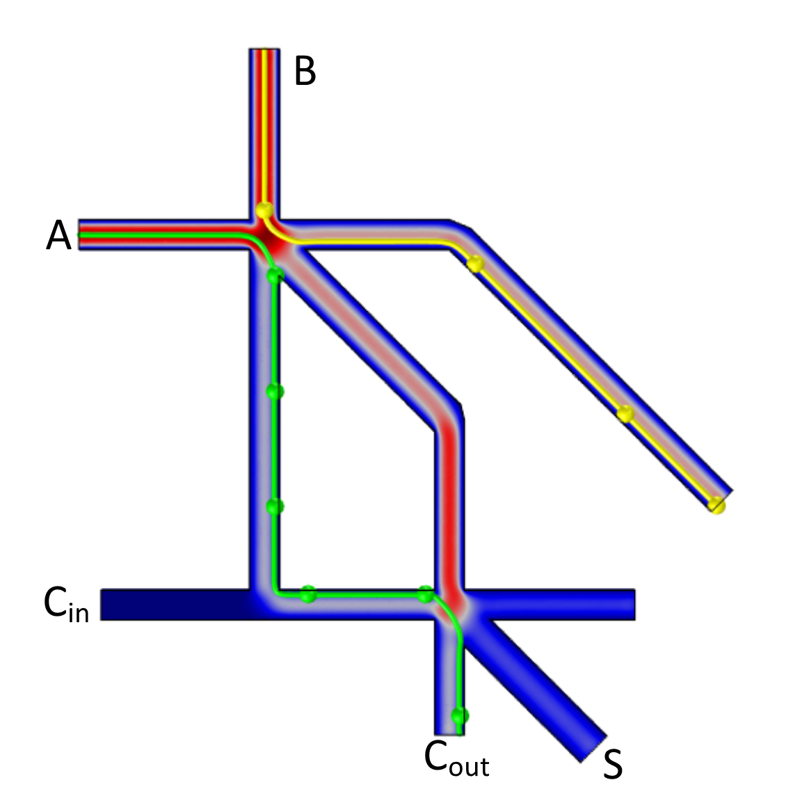
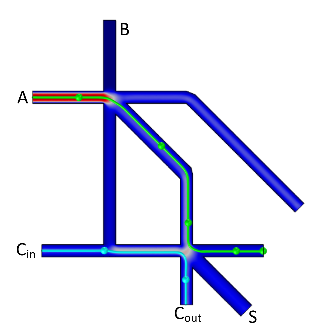
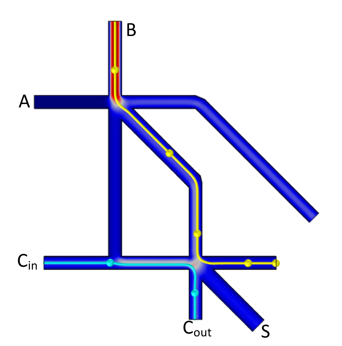
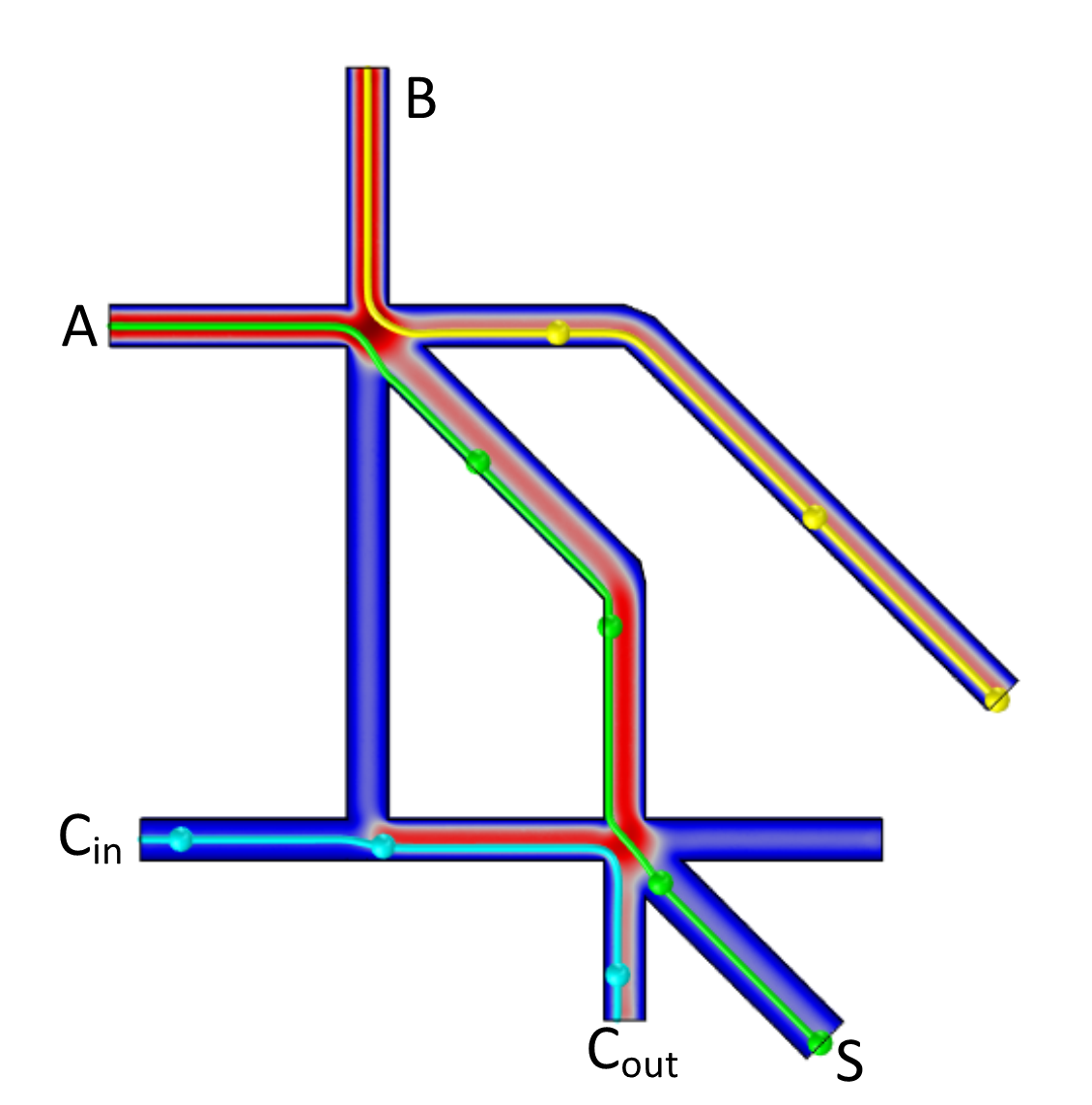
With regard to the functional expansions of the proposed design, the half-adder described above can be cascaded to a full one-bit adder. The function of the full adder is shown in simulation in Fig. 3, where the trajectories of droplets, representing True, are also indicated. When only one of the inputs , or is True, and other inputs are False, a pressure is applied to the fluid in corresponding input channel and the droplet moves along the path of least resistance towards an output channel (Fig. 3abc). If both inputs and are True but is False, the droplets originating in deflect into the drain channel (rightmost output channel in Fig. 3d), and the droplets from move towards the left channel before entering the second half adder junction where it is then deflected into the channel. To ensure that exits through this channel must be short enough for the fluidic resistance of and to be approximately equal. Droplet () deflects to the drain channel when only one of or is True and is True (Fig. 3ef). The fluid streams behave similarly at sequential half adder junctions as in the independent half-adder junctions. () exit through the central junction at the first adder before interacting with fluid stream at the second junction deflecting to and () to drain. When all three inputs are True (Fig. 3g) the presence of flow at is sufficient to deflect through the central channel at the first junction. This then causes droplets from and to exit through and respectively. Thus the output channel implements and the output channel implements . Note, that droplets exit via one of two drain channels (rightmost outputs in Fig. 3) for the following combinations of inputs : 110 (Fig. 3d), 101 (Fig. 3e), 011 (Fig. 3f), 111 (Fig. 3g). This means that the drain output implements disjunction of pairwise conjunctions of input variables . The ability to cascade the junction to form a full adder presents a key potential advantage over similarly simple existing fluidic logic systems such as the one presented by Vestad et al [39].
With regard to practical implementation, our designs suffer from lack of ’autonomy’, as external forces are used to generate and control streams and the overall system behavior. An improvement of the design includes ‘passivisation’ of the device, for example, by using capillary action to move fluids without any external force applied [23]. Another direction of experimental studies will be realisation of many-valued logical gates using divergent droplets labelled with chemical or physical identity, e.g. electrical charges [18, 25], that may selectively influence the interaction of droplets at junctions, e.g. droplets with similar charge will repel and droplets with differing charge will attract at short distances. Use of self-propulsion droplets [20], or chemotactic droplets [6], interacting with fluid flows [38] and with other droplets at longer distances might lead to development of hierarchical architectures of programmable fluidic-droplet systems. Alternative mechanism, e.g. fusion of droplets, by analogy with excitation wave fusion gates [4], could also be explored.
5 Conclusion
A simple microfluidic half-adder junction based on fluidic resistance has been demonstrated both through simulation and experimentation. The input and output states were indicated by the presence of droplets. It has been shown that the same outputs are achieved across a range of flow rates. Simulations were carried out to demonstrate potential for cascading the simple half adder junction to produce a full adder.
Acknowledgments
The research was partially supported by the Leverhulme Trust Visiting Professorship to Martin Hanczyc.
References
- [1] Andrew Adamatzky, editor. Collision Based Computing. Springer, 2002.
- [2] Andrew Adamatzky. Collision-based computing in belousov–zhabotinsky medium. Chaos, Solitons & Fractals, 21(5):1259–1264, 2004.
- [3] Andrew Adamatzky. Slime mould logical gates: exploring ballistic approach. arXiv preprint arXiv:1005.2301, 2010.
- [4] Andrew Adamatzky. Binary full adder, made of fusion gates, in a subexcitable belousov-zhabotinsky system. Physical Review E, 92(3):032811, 2015.
- [5] E.R. Berlekamp, J.H. Conway, and R.K. Guy. Winning ways, vols.1-2. AK Peters, 1982.
- [6] Jitka Cejkova, Matej Novak, Frantisek Stepanek, and Martin M Hanczyc. Dynamics of chemotactic droplets in salt concentration gradients. Langmuir, 30(40):11937–11944, 2014.
- [7] Arthur Conway, editor. Guide to Fluidics. Macdonald, 1971.
- [8] Ben De Lacy Costello, Andy Adamatzky, Ishrat Jahan, and Liang Zhang. Towards constructing one-bit binary adder in excitable chemical medium. Chemical Physics, 381(1):88–99, 2011.
- [9] Joshua Benno Edel and Andrew De Mello. Nanofluidics: nanoscience and nanotechnology. Number 6. Royal Society of Chemistry, 2009.
- [10] David Erickson and Dongqing Li. Integrated microfluidic devices. Analytica Chimica Acta, 507(1):11–26, 2004.
- [11] Mark J Feldstein, Joel P Golden, Chris A Rowe, Brian D MacCraith, and Frances S Ligler. Array biosensor: optical and fluidics systems. Biomedical microdevices, 1(2):139–153, 1999.
- [12] Simion Florea and Ion Dumitrache. Fluidic devices with threshold logic. Automatica, 9(1):47–52, 1973.
- [13] Edward Fredkin and Tommaso Toffoli. Conservative logic. International Journal of Theoretical Physics, 21:219–253, 1982.
- [14] Frank A Gomez. Biological applications of microfluidics. John Wiley & Sons, 2008.
- [15] Alex Groisman, Markus Enzelberger, and Stephen R Quake. Microfluidic memory and control devices. Science, 300(5621):955–958, 2003.
- [16] Yukio-Pegio Gunji, Yuta Nishiyama, Andrew Adamatzky, Theodore E Simos, George Psihoyios, Ch Tsitouras, and Zacharias Anastassi. Robust soldier crab ball gate. Complex systems, 20(2):93, 2011.
- [17] A Healey. Fluidic half-adder, January 23 1973. US Patent 3,712,323.
- [18] Charles D Hendricks. Charged droplet experiments. Journal of Colloid Science, 17(3):249–259, 1962.
- [19] Tsung-Yi Ho. Design automation for digital microfluidic biochips: From fluidic-level toward chip-level. In Solid-State and Integrated Circuit Technology (ICSICT), 2012 IEEE 11th International Conference on, pages 1–4. IEEE, 2012.
- [20] Naoto Horibe, Martin M Hanczyc, and Takashi Ikegami. Mode switching and collective behavior in chemical oil droplets. Entropy, 13(3):709–719, 2011.
- [21] Rohit Karnik, Kenneth Castelino, and Arun Majumdar. Field-effect control of protein transport in a nanofluidic transistor circuit. Applied Physics Letters, 88(12):123114, 2006.
- [22] RO Keefe. Discovery in a fluidic computer, June 28 1974. US Patent 3,821,537.
- [23] Sung-Jin Kim, Yong Taik Lim, Haesik Yang, Yong Beom Shin, Kyuwon Kim, Dae-Sik Lee, Se Ho Park, and Youn Tae Kim. Passive microfluidic control of two merging streams by capillarity and relative flow resistance. Analytical chemistry, 77(19):6494–6499, 2005.
- [24] Clement Kleinstreuer. Modern Fluid Dynamics: Basic Theory and Selected Applications in Macro-and Micro-fluidics, volume 87. Springer Science & Business Media, 2009.
- [25] Victor E Krohn Jr. Glycerol droplets for electrostatic propulsion. Progress in Astronautics and Aeronautics, 9, 1963.
- [26] C.S.S.R. Kumar. Microfluidic Devices in Nanotechnology: Applications. Wiley, 2010.
- [27] Marc J Madou. Solid-State Physics, Fluidics, and Analytical Techniques in Micro-and Nanotechnology, volume 1. CRC Press, 2011.
- [28] Norman Margolus. Physics-like models of computation. Physica D: Nonlinear Phenomena, 10(1):81–95, 1984.
- [29] Richard Mayne and Andrew Adamatzky. On the computing potential of intracellular vesicles. PloS one, 10(10):e0139617, 2015.
- [30] Horton Billy Mitchusson and Warren Raymond Wilbur. Fluid logic components, October22 1963. US Patent 3,107,850.
- [31] Shashi K Murthy, H Zeringue, S Khan, and V Ugaz. Materials and strategies for lab-on-a-chip–biological analysis, cell-material interfaces, and fluidic assembly of nanostructures: symposium held April 14-17, 2009, San Francisco, California, USA, volume 1191. Cambridge University Press, 2009.
- [32] Edwin Oosterbroek and Albert Van den Berg. Lab-on-a-chip: miniaturized systems for (bio) chemical analysis and synthesis. Elsevier, 2003.
- [33] Cyrille Pavlin, WS Griffin, TW Bermel, Norman A Eisenberg, PA Orner, and Charles K Taft, editors. Proceedings of the Fluid Amplification Symposium, 26–28 October 1965, vol. 3. 1965.
- [34] Manu Prakash and Neil Gershenfeld. Microfluidic bubble logic. Science, 315(5813):832–835, 2007.
- [35] Herbert Simon Stephens and Thomas Ephraim Brock, editors. Proceedings of the Cranfield Fluidics Conference, volume 2. British Hydromechanics Research Association, 1968.
- [36] Eujin Um and Je-Kyun Park. Microfluidic droplet adder in micro-channels. 2008.
- [37] Eujin Um and Je-Kyun Park. A microfluidic abacus channel for controlling the addition of droplets. Lab on a Chip, 9(2):207–212, 2009.
- [38] Manuel G Velarde. Drops, liquid layers and the marangoni effect. Philosophical Transactions — Royal Society of London. Series A: Mathematical, Physical and Engineering Sciences, pages 829–842, 1998.
- [39] Tor Vestad, David WM Marr, and Toshinori Munakata. Flow resistance for microfluidic logic operations. Applied Physics Letters, 84(25):5074–5075, 2004.
- [40] J Volcik. Fluidic binary adders. i. Fluidika, 13:14–29, 1975.
- [41] F Yeshaiahu, LP Lee, D Psaltis, and C Yang. Optofluidics fundamentals, devices, and application, 2010.