Sensing Dispersive and Dissipative Forces by an Optomechanical Cavity
Abstract
We experimentally study an optomechanical cavity that is formed between a mechanical resonator, which serves as a movable mirror, and a stationary on-fiber dielectric mirror. A significant change in the behavior of the system is observed when the distance between the fiber’s tip and the mechanical resonator is made smaller than about 1 . The observed effects are attributed to the combined influence of Casimir force, Coulomb interaction due to trapped charges, and optomechanical coupling. The comparison between experimental results and theory yields a partial agreement.
pacs:
46.40.- f, 05.45.- a, 65.40.De, 62.40.+ iThe study of the interaction between a mechanical resonator and nearby bodies is of great importance for the fields of micro electromechanical systems and scanning probe microscopy. For sufficiently short distances the interaction is expected to be dominated by the Casimir force, Lamoreaux (1997); Mohideen and Roy (1998); Chan et al. (2001), which originates from the dependence of the ground state energy of the electromagnetic field upon boundary conditions Casimir (1948); Lifshitz (1956); Milonni (1994); Bordag et al. (2001); Lamoreaux (1999, 2005). For larger distances, however, other mechanisms such as Coulomb interaction between trapped charges and their image charges Denk and Pohl (1991) and local variations in the work function Burnham et al. (1992) commonly dominate the interaction.
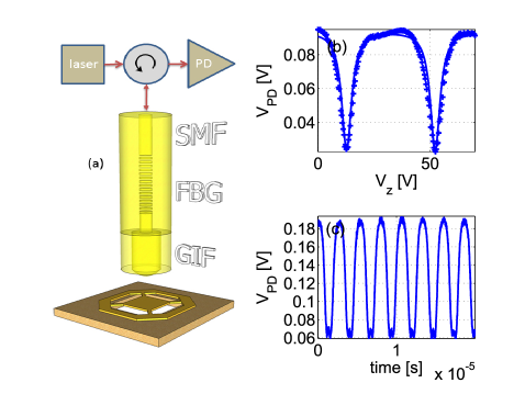
In this study we investigate the effect of interaction between nearby bodies on the dynamics of an optomechanical cavity Braginsky and Manukin (1967); Hane and Suzuki (1996); Gigan et al. (2006); Metzger and K.Karrai (2004); Kippenberg and Vahala (2008); I. Favero et al. (2007); Marquardt and Girvin (2009). In our setup the optomechanical cavity is formed between two mirrors, a stationary fiber Bragg grating (FBG) mirror and a movable mirror made of aluminum in the shape of a trampoline supported by 4 beams [see Fig 1(a)]. The tip of the fiber is blown into a dome shape. Piezoelectric motors are employed for positioning the center of the dome above the center of the trampoline and for controlling the distance between them. The observed response of the optomechanical cavity in the range exhibits rich dynamics resulting from the interplay between back-reaction optomechanical effects and the nonlinear coupling between the interacting bodies. In general, such coupling may result in both a static force due to dispersive interaction, and a friction force due to dissipative (or retarded) interaction Volokitin and Persson (1999). Contrary to some other previously employed techniques, in which only the static force can be measured, we find that the observed response of the optomechanical cavity allows the extraction of both static and friction forces Stipe et al. (2001); Dorofeyev et al. (1999); Gotsmann and Fuchs (2001).
A photo-lithography process is used to pattern a thick aluminum on a high resistivity silicon wafer, into a mechanical resonator in the shape of a trampoline Zaitsev et al. (2011) [see Fig. 1(a)]. Details of the fabrication process can be found elsewhere Suchoi et al. (2014). Measurements are performed at a temperature of and a pressure well below . A graded index fiber (GIF) of pitch is spliced to the end of the single mode fiber (SMF), and its tip is blown into a dome shape of radius . A cryogenic piezoelectric three-axis positioning system having sub-nanometer resolution is employed for manipulating the position of the optical fiber. A tunable laser operating near the Bragg wavelength of the FBG together with an external attenuator are employed to excite the optical cavity. The optical power reflected off the cavity is measured by a photodetector (PD), which is connected to both a spectrum analyzer and to an oscilloscope. Two neighboring optical cavity resonances are seen in panel (b) of Fig. 1, in which the reflected optical power is plotted as a function of the voltage that is applied to the piezoelectric motor, which is employed for controlling the vertical distance between the dome and the trampoline. A time trace in the region of self-excited oscillation (SEO) is shown in panel (c).
The technique of resonance sensing allows measuring both static and friction forces acting on the trampoline mirror. The linear response of the decoupled fundamental mechanical mode of the trampoline is characterized by a complex angular frequency , where is the intrinsic angular resonance frequency of the mode and is its intrinsic damping rate. In general, interaction between the mechanical mode and a given ancilla system may give rise to an external force acting on the mechanical resonator. For a fixed mechanical displacement the force is characterized by its static value, which is denoted by . For simplicity, it is assumed that the time evolution of the ancilla system is governed by a first order equation of motion, which is characterized by a decay rate . To lowest nonvanishing order in the coupling strength between the mechanical resonator and the ancilla system the effect of the interaction effectively modifies the value of the complex angular resonance frequency, which becomes , where the contribution due to back-reaction is give by Zaitsev et al. (2012)
| (1) |
where is the effective mass of the fundamental mechanical mode, is the displacement of the mechanical resonator corresponding to a stationary solution of the equations of motion, and it is assumed that .
In the discussion below, the contribution to due to Casimir force is denoted by , the one due to Coulomb interaction induced by trapped charges by , and the one due to optomechanical coupling by . Both contributions and become negligibly small when the dome-trampoline distance is sufficiently large, whereas the contribution of the optomechanical term can be suppressed by reducing the laser power .
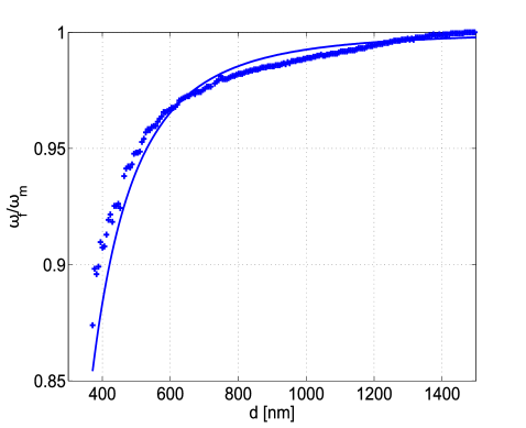
The normalized mechanical resonance frequency is plotted in Fig. 2 as a function of the dome-trampoline distance . The measured values, which are obtained with laser power of and laser wavelength of (the laser is tuned away from the Bragg band of high reflectivity), are labelled by crosses. For these laser parameters optomechanical back-reaction effects are experimentally found to be negligibly small, allowing thus isolating the combined contributions of and . To theoretically estimate these contributions, both the Casimir force and the Coulomb force due to trapped charges are evaluated below as a function of the distance between the dome and the trampoline.
The Casimir force per unit area between a metal plate having plasma frequency and a dielectric plate having a relative dielectric constant separated by a vacuum gap of width can be evaluated using the Lifshitz formula Lifshitz (1956); Milonni (1994); Bordag et al. (2001); Chen et al. (2005); Buhmann and Welsch (2007)
| (2) |
where , the function is given by
| (3) | ||||
where
| (4) | ||||
| (5) |
and where
| (6) | ||||
| (7) |
Note that in the limit and . In Eq. (2) the effect of absorption in the dielectric material has been disregarded and the correction due to finite temperature has been neglected. These approximations are expected to be valid provided that , where is the energy gap of the dielectric material. For the parameters of the current experiment the validity condition reads .
When the distance between the metallic trampoline and the dielectric dome is much smaller than the radius of the dome the mutual force, which is labeled by , can be evaluated using the Derjaguin approximation Derjaguin and Abrikosova (1957) [see Eq. (2)]
| (8) |
Finite metal conductivity may give rise to a friction force associated with the Casimir interaction Volokitin and Persson (1999). The effect of Casimir friction on the mechanical resonator can be characterized by a damping rate, which is denoted by . For the parameters of our device the theoretical expression given in Ref. Volokitin and Persson (1999) yields a value , which is about 7 orders of magnitude smaller than the intrinsic mechanical quality factor, and thus the Casimir friction is not expected to play any significant role in the current experiment Stipe et al. (2001); Dorofeyev et al. (1999); Gotsmann and Fuchs (2001).
Coulomb interaction between trapped charges and their images may give rise to an additional force acting on the mechanical resonator Stipe et al. (2001). In general the force depends on the unknown distribution of trapped charges. In what follows, it is assumed that the force can be expressed in terms of an effective total trapped charge as Marchi et al. (2008)
| (9) |
where is the permittivity constant. Note that for the case where all trapped charges are located on the surface of the dome at the point closest to the trampoline Eq. (9) becomes exact provided that polarizability can be disregarded.
In general, trapped charges can give rise to both, a shift in the effective value of the angular frequency of the mechanical resonator, which is denoted by , and to an added damping rate, which is denoted by . The added damping rate can be evaluated by calculating the damping power generated by dissipative currents on the surface of the metal due to relative motion of trapped charges Stowe et al. (1999); Chumak et al. (2004). The ratio is found to be roughly given by , where is the Debye length ( for aluminum) and where is the conductivity ( for aluminum at ). For the entire range of values of the distance that has been explored in the current experiment , and thus the added damping due to trapped charges is expected to be negligibly small. Moreover, retardation in the redistribution of charges on the surface of the metal due to mechanical motion can be safely disregarded since .
The complex frequency shift induced by the combined effect of Casimir interaction and trapped charges can be evaluated using Eq. (1). As was discussed above, the imaginary part of both and can be safely disregarded. The fixed point value of the displacement of the mechanical resonator, which is denoted by , is found by solving the force balance equation . The normalized measured (crosses) and calculated (solid line) values of the mechanical angular resonance frequency are plotted in Fig. 2 as a function of the distance . The assumed values of experimental parameters that have been used in the calculation are listed in the caption of Fig. 2.
As can be seen from Fig. 2, the smallest measured value of prior to pull-in is about . As was previously pointed out in Ref. Buks and Roukes (2001), pull-in due to thermal activation (which is estimated to be much more efficient than quantum tunneling for the parameters of the current experiment) is theoretically expected to occur at significantly smaller values of the ratio .
In the above-discussed measurements back-reaction effects originating from coupling between the optical cavity and the mechanical resonator have been suppressed by keeping the injected optical power at a relatively low level. Such effects, however, can significantly modify the dynamics at higher values of . In general, the effect of radiation pressure typically governs the optomechanical coupling when the finesse of the optical cavity is sufficiently high Kippenberg et al. (2005); Rokhsari et al. (2005); Arcizet et al. (2006a); Gigan et al. (2006); Kleckner and Bouwmeester (2006); Kippenberg and Vahala (2008), whereas, bolometric effects can contribute to the optomechanical coupling when optical absorption by the vibrating mirror is significant Metzger and K.Karrai (2004); Jourdan et al. (2008); Marino and Marin (2011); Metzger et al. (2008); Restrepo et al. (2011); Liberato et al. (2010); Marquardt et al. (2006); Paternostro et al. (2006); Yuvaraj et al. (2013), and when the thermal relaxation rate is comparable to the mechanical resonance frequency Aubin et al. (2004); Marquardt et al. (2006); Paternostro et al. (2006); De Liberato et al. (2011). Bolometric optomechanical coupling Metzger et al. (2008); Metzger and K.Karrai (2004); Aubin et al. (2004); Jourdan et al. (2008); Zaitsev et al. (2011, 2012) may result in many intriguing phenomena such as mode cooling and SEO Hane and Suzuki (1996); Kim and Lee (2002); Aubin et al. (2004); Carmon et al. (2005); Marquardt et al. (2006); Corbitt et al. (2006); Carmon and Vahala (2007); Metzger et al. (2008); Bagheri et al. (2011); Rugar et al. (1989); Arcizet et al. (2006b); Forstner et al. (2012); Stapfner et al. (2013).
In the device under study in the current experiment the dominant underlying mechanism responsible for the optomechanical coupling is optical absorption by the suspended mirror Zaitsev et al. (2011). Such absorption gives rise to heating, which in-turn causes thermal deformation of the suspended structure due to mismatch between thermal expansion coefficients of the suspended mirror made of aluminum and the supporting silicon substrate Yuvaraj et al. (2013). Thermal deformation Metzger et al. (2008) gives rise to a thermal force, which is expressed as , where is assumed to be a constant, and where is the offset between the temperature of the suspended mirror and the temperature of the supporting substrate . In the static limit the force, which is denoted for this case by , can be evaluated by simultaneously solving the force balance equation , where denotes the mechanical displacement, and the thermal balance equation , where is the heating power divided by the thermal heat capacity of the trampoline and where is the thermal decay rate.
Optical interference in the cavity gives rise to displacement dependence of the term , which is given by , where is the heating coefficient due to optical absorption and where is the intra-cavity optical power incident on the suspended mirror. The function depends on the properties of the optical cavity. The finesse of the optical cavity is limited by loss mechanisms that give rise to optical energy leaking out of the cavity. The main escape routes are through the on-fiber static reflector, through absorption by the metallic mirror, and through radiation. The corresponding transmission probabilities are respectively denoted by , and . In terms of these parameters, the function is given by Zaitsev et al. (2011)
| (10) |
where is the displacement of the mirror relative to a point , at which the energy stored in the optical cavity in steady state obtains a local maximum, and where is the cavity finesse. The reflection probability is given in steady state by Yurke and Buks (2006); Zaitsev et al. (2011).
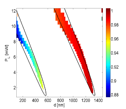
With sufficiently high laser power the system can be driven into SEO. The color-coded plot seen in Fig. 3 exhibits the measured normalized value of SEO frequency vs. dome-trampoline distance and laser power . No SEO is observed in the white regions. The two colored regions in Fig. 3 represent SEO occurring near two optical resonances (OR). The one seen on the left is the first OR of the cavity, which occurs with the smallest value of , and the one seen on the right is the second one. As can be seen from Fig. 3, the SEO frequency measured near the first OR is significantly smaller. Moreover, the lowest input laser power value for which SEO occurs near the first OR is significantly higher (the value is times larger than the value corresponding to the second OR).
The black solid lines in Fig. 3 represent the theoretically calculated bifurcation lines, which are found from solving the equation , where , and , which is given by Eq. (1), is calculated for the case of the above-discussed bolometric coupling between the mechanical resonator and the optical cavity. In spite of the fact that the contribution of both Casimir and Coulomb interactions to the effective mechanical damping rate is theoretically expected to be negligibly small, the experimental results clearly indicate that the damping rate is significantly larger near the first OR, as can be seen from the significantly higher observed value of laser power threshold . Further study is needed in order to identify the underlying mechanism responsible for this contactless friction that is observed at relatively short distances.
In summary, sensitive detection of both dispersive and dissipative forces is demonstrated using an optomechanical cavity. The combined effect of Casimir force, Coulomb interaction due to trapped charges and bolometric optomechanical coupling on the mechanical resonator is theoretically estimated. Partial agreement is found in the comparison between theory and experimental findings.
This work was supported by the Israel Science Foundation, the Binational Science Foundation, the Security Research Foundation at Technion and the Russell Berrie Nanotechnology Institute.
References
- Lamoreaux (1997) S. K. Lamoreaux, Physical Review Letters 78, 5 (1997).
- Mohideen and Roy (1998) U. Mohideen and A. Roy, Physical Review Letters 81, 4549 (1998).
- Chan et al. (2001) H. Chan, V. Aksyuk, R. Kleiman, D. Bishop, and F. Capasso, Physical Review Letters 87, 211801 (2001).
- Casimir (1948) H. B. Casimir, Proc. K. Ned. Akad. Wet. 51, 793 (1948).
- Lifshitz (1956) E. Lifshitz, Sov. Phys. 2, 73 (1956).
- Milonni (1994) P. W. Milonni, The Quantum Vacuum (Academic Press, San Diego, 1994).
- Bordag et al. (2001) M. Bordag, U. Mohideen, and V. M. Mostepanenko, Physics Reports 353, 1 (2001).
- Lamoreaux (1999) S. K. Lamoreaux, American Journal of Physics 67, 850 (1999).
- Lamoreaux (2005) S. K. Lamoreaux, Reports on Progress in Physics 68, 201 (2005).
- Denk and Pohl (1991) W. Denk and D. W. Pohl, Applied physics letters 59, 2171 (1991).
- Burnham et al. (1992) N. Burnham, R. Colton, and H. Pollock, Physical Review Letters 69, 144 (1992).
- Braginsky and Manukin (1967) V. Braginsky and A. Manukin, Soviet Physics JETP 25, 653 (1967).
- Hane and Suzuki (1996) K. Hane and K. Suzuki, Sensors and Actuators A: Physical 51, 179 (1996).
- Gigan et al. (2006) S. Gigan, H. R. Böhm, M. Paternostro, F. Blaser, J. B. Hertzberg, K. C. Schwab, D. Bauerle, M. Aspelmeyer, and A.Zeilinger, Nature 444, 67 (2006).
- Metzger and K.Karrai (2004) C. H. Metzger and K.Karrai, Nature 432, 1002 (2004).
- Kippenberg and Vahala (2008) T. J. Kippenberg and K. J. Vahala, Science 321, 1172 (2008).
- I. Favero et al. (2007) C. M. I. Favero, S. Camerer, D. Konig, H. Lorenz, J. P. Kotthaus, and K. Karrai, Appl. Phys. Lett. 90, 104101 (2007).
- Marquardt and Girvin (2009) F. Marquardt and S. M. Girvin, Physics 2, 40 (2009).
- Volokitin and Persson (1999) A. Volokitin and B. Persson, Journal of Physics: Condensed Matter 11, 345 (1999).
- Stipe et al. (2001) B. Stipe, H. Mamin, T. Stowe, T. Kenny, and D. Rugar, Physical Review Letters 87, 096801 (2001).
- Dorofeyev et al. (1999) I. Dorofeyev, H. Fuchs, G. Wenning, and B. Gotsmann, Physical review letters 83, 2402 (1999).
- Gotsmann and Fuchs (2001) B. Gotsmann and H. Fuchs, Physical Review Letters 86, 2597 (2001).
- Zaitsev et al. (2011) S. Zaitsev, A. K. Pandey, O. Shtempluck, and E. Buks, Phys. Rev. E 84, 046605 (2011).
- Suchoi et al. (2014) O. Suchoi, L. Ella, O. Shtempluk, and E. Buks, Physical Review A 90, 033818 (2014).
- Zaitsev et al. (2012) S. Zaitsev, O. Gottlieb, and E. Buks, Nonlinear Dyn. 69, 1589 (2012).
- Chen et al. (2005) F. Chen, U. Mohideen, G. Klimchitskaya, and V. Mostepanenko, Physical Review A 72, 020101 (2005).
- Buhmann and Welsch (2007) S. Y. Buhmann and D.-G. Welsch, Progress in Quantum Electronics 31, 51 (2007).
- Derjaguin and Abrikosova (1957) B. Derjaguin and I. Abrikosova, Sov. Phys. JETP 3, 819 (1957).
- Marchi et al. (2008) F. Marchi, R. Dianoux, H. Smilde, P. Mur, F. Comin, and J. Chevrier, Journal of electrostatics 66, 538 (2008).
- Stowe et al. (1999) T. Stowe, T. Kenny, D. Thomson, and D. Rugar, Applied Physics Letters 75, 2785 (1999).
- Chumak et al. (2004) A. Chumak, P. Milonni, and G. Berman, Physical Review B 70, 085407 (2004).
- Buks and Roukes (2001) E. Buks and M. L. Roukes, EuroPhys. Lett. 54, 220 (2001).
- Kippenberg et al. (2005) T. J. Kippenberg, H. Rokhsari, T. Carmon, A. Scherer, and K. J. Vahala, Phys. Rev. Lett. 95, 033901 (2005).
- Rokhsari et al. (2005) H. Rokhsari, T. Kippenberg, T. Carmon, and K. Vahala, Opt. Express 13, 5293 (2005).
- Arcizet et al. (2006a) O. Arcizet, P. F.Cohadon, T. Briant, M. Pinard, and A. Heidmann, Nature 444, 71 (2006a).
- Kleckner and Bouwmeester (2006) D. Kleckner and D. Bouwmeester, Nature 444, 75 (2006).
- Jourdan et al. (2008) G. Jourdan, F. Comin, and J. Chevrier, Phys. Rev. Lett. 101, 133904 (2008).
- Marino and Marin (2011) F. Marino and F. Marin, Phys. Rev. E 83, 015202 (2011).
- Metzger et al. (2008) C. Metzger, M. Ludwig, C. Neuenhahn, A. Ortlieb, I. Favero, K. Karrai, and F. Marquardt, Phys. Rev. Lett. 101, 133903 (2008), eprint 0711.2661.
- Restrepo et al. (2011) J. Restrepo, J. Gabelli, C. Ciuti, and I. Favero, Comptes Rendus Physique 12, 1011.3911 (2011).
- Liberato et al. (2010) S. D. Liberato, N. Lambert, and F. Nori, arXiv:1011.6295 (2010), eprint 1011.6295.
- Marquardt et al. (2006) F. Marquardt, J. G. E. Harris, and S. M. Girvin, Phys. Rev. Lett. 96, 103901 (2006).
- Paternostro et al. (2006) M. Paternostro, S. Gigan, M. S. Kim, F. Blaser, H. R. Böhm, and M. Aspelmeyer, New J. Phys. 8, 107 (2006).
- Yuvaraj et al. (2013) D. Yuvaraj, M. B. Kadam, O. Shtempluck, and E. Buks, JMEMS 22, 430 (2013).
- Aubin et al. (2004) K. Aubin, M. Zalalutdinov, T. Alan, R. Reichenbach, R. Rand, A. Zehnder, J. Parpia, and H. Craighead, J. MEMS 13, 1018 (2004).
- De Liberato et al. (2011) S. De Liberato, N. Lambert, and F. Nori, Phys. Rev. A 83, 033809 (2011).
- Kim and Lee (2002) K. Kim and S. Lee, J. Appl. Phys. 91, 4715 (2002).
- Carmon et al. (2005) T. Carmon, H. Rokhsari, L. Yang, T. J. Kippenberg, and K. J. Vahala, Phys. Rev. Lett. 94, 223902 (2005).
- Corbitt et al. (2006) T. Corbitt, D. Ottaway, E. Innerhofer, J. Pelc, and N. Mavalvala, Phys. Rev. A 74, 21802 (2006).
- Carmon and Vahala (2007) T. Carmon and K. J. Vahala, Phys. Rev. Lett. 98, 123901 (2007).
- Bagheri et al. (2011) M. Bagheri, M. Poot, M. Li, W. P. H. Pernice, and H. X. Tang, Nature Nanotechnology 6, 726 (2011).
- Rugar et al. (1989) D. Rugar, H. J. Mamin, and P. Guethner, Applied Physics Letters 55, 2588 (1989).
- Arcizet et al. (2006b) O. Arcizet, P.-F. Cohadon, T. Briant, M. Pinard, A. Heidmann, J.-M. Mackowski, C. Michel, L. Pinard, O. Français, and L. Rousseau, Phys Rev Lett 97, 133601 (2006b).
- Forstner et al. (2012) S. Forstner, S. Prams, J. Knittel, E. D. van Ooijen, J. D. Swaim, G. I. Harris, A. Szorkovszky, W. P. Bowen, and H. Rubinsztein-Dunlop, Phys. Rev. Lett. 108, 120801 (2012).
- Stapfner et al. (2013) S. Stapfner, L. Ost, D. Hunger, J. Reichel, I. Favero, and E. M. Weig, Applied Physics Letters 102, 151910 (pages 5) (2013).
- Yurke and Buks (2006) B. Yurke and E. Buks, J. Lightwave Tech. 24, 5054 (2006).