Superharmonic Resonances in a Strongly Coupled Cavity-Atom System
Abstract
We study a system consisting of a superconducting flux qubit strongly coupled to a microwave cavity. The fundamental cavity mode is externally driven and the response is investigated in the weak nonlinear regime. We find that near the crossing point, at which the resonance frequencies of the cavity mode and qubit coincide, the sign of the Kerr coefficient changes, and consequently the type of nonlinear response changes from softening to hardening. Furthermore, the cavity response exhibits superharmonic resonances when the ratio between the qubit frequency and the cavity fundamental mode frequency is tuned close to an integer value. The nonlinear response is characterized by the method of intermodulation and both signal and idler gains are measured. The experimental results are compared with theoretical predictions and good qualitative agreement is obtained. The superharmonic resonances have potential for applications in quantum amplification and generation of entangled states of light.
pacs:
85.25.Cp, 03.65.Ge, 42.50.PqCavity quantum electrodynamics (CQED) Haroche and Kleppner (1989) is the study of the interaction between photons confined in a cavity and atoms (natural or artificial). The interaction is commonly described by the Rabi or Jaynes-Cummings Hamiltonians Shore and Knight (1993), and it has been the subject of numerous theoretical and experimental investigations. An on-chip CQED system can be realized by integrating a Josephson qubit Clarke and Wilhelm (2008); Devoret and Schoelkopf (2013); You and Nori (2011) (playing the role of an artificial atom) with a superconducting microwave resonator (cavity) Blais et al. (2004); Wallraff et al. (2004); Schoelkopf and Girvin (2008). Superconducting CQED systems have generated a fast growing interest due to the possibility to reach the strong Wallraff et al. (2004) and ultra-strong Niemczyk et al. (2010); Forn-Díaz et al. (2010) coupling regimes, and due to potential applications in quantum information processing Devoret and Schoelkopf (2013); Barends et al. (2014); Chow et al. (2014); Ristè et al. (2015).
In this study we investigate the driven dynamics of a strongly interacting system composed of a superconducting flux qubit Mooij et al. (1999); Orlando et al. (1999) and a coplanar waveguide (CPW) microwave cavity Niemczyk et al. (2010); Abdumalikov Jr et al. (2008); Bal et al. (2012); Orgiazzi et al. (2014); Jerger et al. (2012); Oelsner et al. (2010); Inomata et al. (2012). The nonlinear cavity response Serban et al. (2010); Laflamme and Clerk (2011); Siddiqi et al. (2004); Lupaşcu et al. (2006); Boaknin et al. (2007); Mallet et al. (2009); Boissonneault et al. (2008, 2010, 2014, 2012, 2009); Reed et al. (2010); Ong et al. (2013, 2011); Bishop et al. (2009) is measured as a function of the magnetic flux that is applied to the qubit. At weak driving and when the ratio between the qubit frequency and the cavity fundamental mode frequency is tuned close to the value the common Jaynes-Cummings resonance, which henceforth is referred to as the primary resonance, is observed. With stronger driving, however, and when the ratio is tuned close to integer values larger than unity, superharmonic resonances appear in the measured response. Intermodulation (IMD) measurements are employed to characterize the nonlinear response Castellanos-Beltran and Lehnert (2007); Vijay et al. (2011); Yurke and Buks (2006). The results are compared with the predictions of a theoretical model, which is based on linearization of the equations of motion that govern the dynamics of the CQED system under study.
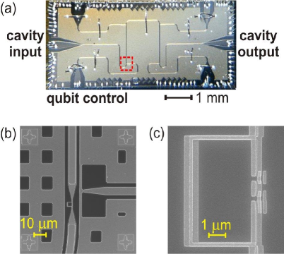
The investigated device contains a CPW cavity weakly coupled to two ports that are used for performing microwave transmission measurements [see Fig. 1(a)]. Two persistent current flux qubits Mooij et al. (1999), consisting of a superconducting loop interrupted by four Josephson junctions [see Fig. 1(c)], are inductively coupled to the CPW resonator [see Fig. 1(b)]. In the current experiment, however, only one qubit significantly affects the cavity mode response, whereas the other one is made effectively decoupled by detuning its energy gap away from the mode frequency. A CPW line terminated by a low inductance shunt is used to send microwave pulses for coherent qubit control [see Fig. 1(b)]. The device is fabricated on a high resistivity silicon substrate, in a two-step process. In the first step, the resonator and the control lines are defined using optical lithography, evaporation of a thick aluminum layer and liftoff. In the second step, a bilayer resist is patterned by electron-beam lithography. Subsequently, shadow evaporation of two aluminum layers, and thick respectively, followed by liftoff define the qubit junctions.
The chip is enclosed inside a copper package, which is cooled by a dilution refrigerator to a temperature of . Both passive and active shielding methods are employed to suppress magnetic field noise. While passive shielding is performed using a three-layer high permeability metal, an active magnetic field compensation system placed outside the cryostat is used to actively reduce low-frequency magnetic field noise. A set of superconducting coils is used to apply DC magnetic flux. Qubit state control is performed using shaped microwave pulses. Attenuators and filters are installed at different cooling stages along the transmission lines for qubit control and readout. A detailed description of sample fabrication and experimental setup can be found in Orgiazzi et al. (2014); Bal et al. (2012).
The main theoretical results needed for analyzing the experimental findings are briefly described below [derivations are given in the supplemental material (SM)]. The circulating current states of the qubit are labeled as and . The coupling between the cavity mode and the qubit is described by the term in the system Hamiltonian, where () is a cavity mode annihilation (creation) operator, and is the coupling coefficient. In the presence of an externally applied magnetic flux, the energy gap between the qubit ground state and first excited state is taken to be given by (see SM section I.A), where
| (1) |
() is the circulating current associated with the state (), is the flux quantum, is the externally applied magnetic flux and is the qubit energy gap for the case where .
The decoupled cavity mode is characterized by an angular resonance frequency , Kerr coefficient , linear damping rate and cubic damping (two-photon absorption) rate . The response of the decoupled cavity in the weak nonlinear regime (in which, nonlinearity is taken into account to lowest non-vanishing order) can be described by introducing the complex and mode amplitude dependent cavity angular resonance frequency , which is given by
| (2) |
where is the averaged number of photons occupying the cavity mode. The imaginary part of represents the effect of damping and the terms proportional to determine the weak nonlinear response. The effect of the flux qubit on the cavity response in the weak nonlinear regime is theoretically evaluated in sections I and II of the SM for the case where . The coupling between the cavity mode and the qubit gives rise to a resonance splitting. The steady state cavity mode response for the case where the qubit mainly occupies the state (ground and first excited states) is found to be equivalent to the response of a mode having effective complex cavity angular resonance frequency given by
| (3) |
where is the Bloch-Siegert shift Forn-Díaz et al. (2010) (see SM section II). The term is given by (see SM section I.I)
| (4) |
is the flux dependent effective coupling coefficient, where the coefficient is given by
| (5) |
is the detuning between the angular frequency of the externally injected pump tone and the qubit angular resonance frequency , and () is the qubit longitudinal (transverse) relaxation time. Note that when and when the qubit mainly occupies the state the term gives rise to a shift in the mode angular frequency approximately given by and a shift in the value of the Kerr coefficient approximately given by . Similar theoretical results have been obtained in Ref. Boissonneault et al. (2008), in which the unitary transformation that diagonalizes the Hamiltonian of the closed system has been applied to the system’s master equation.
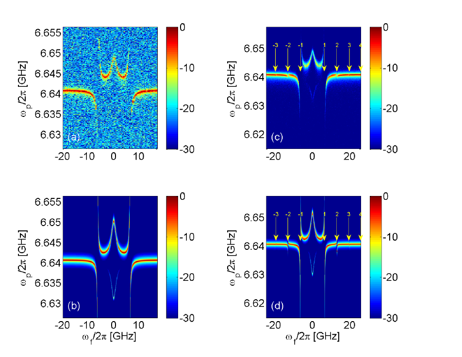
The effect of the qubit on cavity response is experimentally investigated using transmission measurements. The color coded plots in Fig. 2 exhibit the measured (panels a and c) and calculated (panels b and d) cavity transmission (in dB units) vs. , for the case where the power injected into the cavity is dBm (panels a and b) and dBm (panels c and d). In the first step of the theoretical calculation, which has generated the theoretical predictions plotted in panels b and d, fixed points are found by calculating steady state solutions of the equations of motion that govern the dynamics of the system (see SM section I.I). Then in the second step input-output relations are employed in order to calculate the cavity transmission (see SM section I.E) Gardiner and Collett (1985). The assumed device parameters are listed in the caption of Fig. 2.
While the cavity response seen in panels a and b of Fig. 2 is nearly linear, nonlinearity is observed in the results depicted in panels c and d, which are obtained at higher input power. The measured response exhibits hardening (softening) when (), for the case where the qubit mainly occupies its ground state. The opposite behavior is obtained when the qubit mainly occupies the first excited state. The probability for this to happen, which depends on the ratio between thermal energy and qubit energy gap, is non-negligible in the current experiment. The comparison between the experimental results (panels a and c) and the theoretical predictions (panels b and d, respectively) yields an acceptable agreement.
It is well known that the flux qubit is expected to strongly affect the response of the cavity mode near the primary resonance, i.e. when the ratio is tuned close to unity (see the points labeled by in panels c and d of Fig. 2). With sufficiently large driving amplitude, however, higher order nonlinear processes may give rise to superharmonic resonances, which occur near the points at which the ratio is an integer larger than unity (see the points labeled by , and in panels c and d of Fig. 2). The cavity response near a superharmonic resonance is theoretically evaluated in section III of the SM. It is found that the same Eq. (4) can be used to describe the effect of the flux qubit on cavity response near a superharmonic resonance, provided that the coupling coefficient is replaced by , which is given by (see SM section III)
| (6) |
where is the ’th Bessel function of the first kind, and the detuning is replaced by , where at the superharmonic resonance . As can be seen by comparing panels c and d of Fig. 2, the calculated and measured cavity response near the superharmonic resonances exhibit an acceptable agreement.
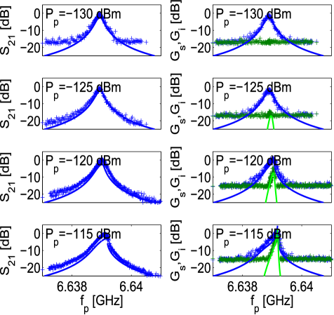
In general, nonlinear cavity response is commonly employed for frequency mixing, which in turn can be used for signal amplification Castellanos-Beltran and Lehnert (2007); Vijay et al. (2011); Castellanos-Beltran et al. (2008); Bergeal et al. (2010); Hatridge et al. (2011) and noise squeezing Castellanos-Beltran et al. (2008); Yurke and Buks (2006). An amplifier based on flux qubits has been recently demonstrated in Ref. Rehák et al. (2014). Here we employ the method of IMD to characterize frequency mixing. In this method, two monochromatic tones are combined and injected into the cavity: an intense pump tone at angular frequency and amplitude , and a weaker signal tone at angular frequency and amplitude . The cavity transmission is measured and the spectral amplitude of the output signal tone at frequency , which is labeled by , and the spectral amplitude of the so-called idler tone at frequency , which is labeled by , are recorded. The corresponding signal gain and idler gain are determined, and the experimental findings are compared with the theoretical predictions, which are based on the linearized equations of motion of the system (see SM section I.L).
The results are exhibited in Fig. 3, in which the cavity transmission (left panels) and the signal and idler gains (right panels) are plotted vs. pump frequency for different values of the pump input power . The magnetic flux for these measurements is set to a value for which and . Relatively good agreement between data and theory (see SM section I.L) is found for the results seen in Fig. 3, however, the deviation between data and theory becomes larger at higher powers. Further study is needed in order to identify the sources of discrepancy, and to improve the accuracy of the theoretical predictions accordingly.
In summary, superharmonic resonances in the device under study have been experimentally observed. We theoretically show that a relatively simple CQED model of a system composed of two coupled elements, a single cavity mode having no intrinsic nonlinearity and a two-level system, can account for the main experimental findings. Further study will aim at expanding the range of validity of the theoretical predictions in order to account for the experimental results at higher levels of input power. Future experiments will explore the possibility of exploiting nonlinearity for improving the fidelity of qubit readout and employ superharmonic resonances for generating highly correlated states of the microwave cavity field (e.g. the creation of entangled pairs of microwave photons near the superharmonic resonance via two-photon stimulated emission events).
We thank Feyruz Kitapli and Pol Forn-Díaz for useful discussions. This research is supported by the Gerald Schwartz and Heather Reisman Foundation, NSERC, Industry Canada, CMC, CFI, Ontario MRI and the Israeli Science Foundation.
References
- Haroche and Kleppner (1989) S. Haroche and D. Kleppner, Phys. Today 42, 24 (1989).
- Shore and Knight (1993) B. W. Shore and P. L. Knight, Journal of Modern Optics 40, 1195 (1993).
- Clarke and Wilhelm (2008) J. Clarke and F. K. Wilhelm, Nature 453, 1031 (2008).
- Devoret and Schoelkopf (2013) M. Devoret and R. Schoelkopf, Science 339, 1169 (2013).
- You and Nori (2011) J. You and F. Nori, Nature 474, 589 (2011).
- Blais et al. (2004) A. Blais, R.-S. Huang, A. Wallraff, S. Girvin, and R. J. Schoelkopf, Physical Review A 69, 062320 (2004).
- Wallraff et al. (2004) A. Wallraff, D. I. Schuster, A. Blais, L. Frunzio, R.-S. Huang, J. Majer, S. Kumar, S. M. Girvin, and R. J. Schoelkopf, Nature 431, 162 (2004).
- Schoelkopf and Girvin (2008) R. Schoelkopf and S. Girvin, Nature 451, 664 (2008).
- Niemczyk et al. (2010) T. Niemczyk, F. Deppe, H. Huebl, E. Menzel, F. Hocke, M. Schwarz, J. Garcia-Ripoll, D. Zueco, T. Hümmer, E. Solano, et al., Nature Physics 6, 772 (2010).
- Forn-Díaz et al. (2010) P. Forn-Díaz, J. Lisenfeld, D. Marcos, J. J. García-Ripoll, E. Solano, C. Harmans, and J. Mooij, Physical Review Letters 105, 237001 (2010).
- Barends et al. (2014) R. Barends, J. Kelly, A. Megrant, A. Veitia, D. Sank, E. Jeffrey, T. White, J. Mutus, A. Fowler, B. Campbell, et al., Nature 508, 500 (2014).
- Chow et al. (2014) J. M. Chow, J. M. Gambetta, E. Magesan, D. W. Abraham, A. W. Cross, B. Johnson, N. A. Masluk, C. A. Ryan, J. A. Smolin, S. J. Srinivasan, et al., Nature communications 5, 1 (2014).
- Ristè et al. (2015) D. Ristè, S. Poletto, M.-Z. Huang, A. Bruno, V. Vesterinen, O.-P. Saira, and L. DiCarlo, Nature communications 6, 1 (2015).
- Orgiazzi et al. (2014) J.-L. Orgiazzi, C. Deng, D. Layden, R. Marchildon, F. Kitapli, F. Shen, M. Bal, F. Ong, and A. Lupascu, arXiv:1407.1346 (2014).
- Mooij et al. (1999) J. E. Mooij, T. P. Orlando, L. Levitov, L. Tian, C. H. V. der Wal, and S. Lloyd, Science 285, 1036 (1999).
- Orlando et al. (1999) T. P. Orlando, J. E. Mooij, L. Tian, C. H. van der Wal, L. S. Levitov, S. Lloyd, and J. J. Mazo, Phys. Rev. B 60, 15398 (1999).
- Abdumalikov Jr et al. (2008) A. A. Abdumalikov Jr, O. Astafiev, Y. Nakamura, Y. A. Pashkin, and J. Tsai, Physical review b 78, 180502 (2008).
- Bal et al. (2012) M. Bal, C. Deng, J.-L. Orgiazzi, F. Ong, and A. Lupascu, Nature communications 3, 1324 (2012).
- Jerger et al. (2012) M. Jerger, S. Poletto, P. Macha, U. Hübner, E. Il ichev, and A. V. Ustinov, Applied Physics Letters 101, 042604 (2012).
- Oelsner et al. (2010) G. Oelsner, S. H. W. van der Ploeg, P. Macha, U. Hübner, D. Born, S. Anders, E. Il’ichev, H.-G. Meyer, M. Grajcar, S. Wünsch, et al., Phys. Rev. B 81, 172505 (2010), URL http://link.aps.org/doi/10.1103/PhysRevB.81.172505.
- Inomata et al. (2012) K. Inomata, T. Yamamoto, P.-M. Billangeon, Y. Nakamura, and J. Tsai, Physical Review B 86, 140508 (2012).
- Serban et al. (2010) I. Serban, M. Dykman, and F. Wilhelm, Physical Review A 81, 022305 (2010).
- Laflamme and Clerk (2011) C. Laflamme and A. A. Clerk, Physical Review A 83, 033803 (2011).
- Siddiqi et al. (2004) I. Siddiqi, R. Vijay, F. Pierre, C. Wilson, M. Metcalfe, C. Rigetti, L. Frunzio, and M. Devoret, Physical review letters 93, 207002 (2004).
- Lupaşcu et al. (2006) A. Lupaşcu, E. Driessen, L. Roschier, C. Harmans, and J. Mooij, Physical review letters 96, 127003 (2006).
- Boaknin et al. (2007) E. Boaknin, V. Manucharyan, S. Fissette, M. Metcalfe, L. Frunzio, R. Vijay, I. Siddiqi, A. Wallraff, R. Schoelkopf, and M. Devoret, arXiv:0702445 (2007).
- Mallet et al. (2009) F. Mallet, F. R. Ong, A. Palacios-Laloy, F. Nguyen, P. Bertet, D. Vion, and D. Esteve, Nature Physics 5, 791 (2009).
- Boissonneault et al. (2008) M. Boissonneault, J. Gambetta, and A. Blais, Physical Review A 77, 060305 (2008).
- Boissonneault et al. (2010) M. Boissonneault, J. Gambetta, and A. Blais, Physical review letters 105, 100504 (2010).
- Boissonneault et al. (2014) M. Boissonneault, A. Doherty, F. Ong, P. Bertet, D. Vion, D. Esteve, and A. Blais, Physical Review A 89, 022324 (2014).
- Boissonneault et al. (2012) M. Boissonneault, A. Doherty, F. Ong, P. Bertet, D. Vion, D. Esteve, and A. Blais, Physical Review A 85, 022305 (2012).
- Boissonneault et al. (2009) M. Boissonneault, J. M. Gambetta, and A. Blais, Physical Review A 79, 013819 (2009).
- Reed et al. (2010) M. Reed, L. DiCarlo, B. Johnson, L. Sun, D. Schuster, L. Frunzio, and R. Schoelkopf, Physical review letters 105, 173601 (2010).
- Ong et al. (2013) F. Ong, M. Boissonneault, F. Mallet, A. Doherty, A. Blais, D. Vion, D. Esteve, and P. Bertet, Physical Review Letters 110, 047001 (2013).
- Ong et al. (2011) F. R. Ong, M. Boissonneault, F. Mallet, A. Palacios-Laloy, A. Dewes, A. Doherty, A. Blais, P. Bertet, D. Vion, and D. Esteve, Physical review letters 106, 167002 (2011).
- Bishop et al. (2009) L. S. Bishop, J. Chow, J. Koch, A. Houck, M. Devoret, E. Thuneberg, S. Girvin, and R. Schoelkopf, Nature Physics 5, 105 (2009).
- Castellanos-Beltran and Lehnert (2007) M. Castellanos-Beltran and K. Lehnert, Applied Physics Letters 91, 083509 (2007).
- Vijay et al. (2011) R. Vijay, D. Slichter, and I. Siddiqi, Physical review letters 106, 110502 (2011).
- Yurke and Buks (2006) B. Yurke and E. Buks, J. Lightwave Tech. 24, 5054 (2006).
- Gardiner and Collett (1985) C. W. Gardiner and M. J. Collett, Phys. Rev. A 31, 3761 (1985).
- Castellanos-Beltran et al. (2008) M. Castellanos-Beltran, K. Irwin, G. Hilton, L. Vale, and K. Lehnert, Nature Physics 4, 929 (2008).
- Bergeal et al. (2010) N. Bergeal, F. Schackert, M. Metcalfe, R. Vijay, V. Manucharyan, L. Frunzio, D. Prober, R. Schoelkopf, S. Girvin, and M. Devoret, Nature 465, 64 (2010).
- Hatridge et al. (2011) M. Hatridge, R. Vijay, D. Slichter, J. Clarke, and I. Siddiqi, Physical Review B 83, 134501 (2011).
- Rehák et al. (2014) M. Rehák, P. Neilinger, M. Grajcar, G. Oelsner, U. Hübner, E. Il’ichev, and H.-G. Meyer, Applied Physics Letters 104, 162604 (2014).