Plasma optical modulators for intense lasers
Abstract
Optical modulators can be made nowadays with high modulation speed, broad bandwidth, while being compact, owing to the recent advance in material science and microfabrication technology. However, these optical modulators usually work for low intensity light beams. Here, we present an ultrafast, plasma-based optical modulator, which can directly modulate high power lasers with intensity up to W/cm2 level to produce an extremely broad spectrum with a fractional bandwidth over 100%, extending to the mid-infrared regime in the low-frequency side. This concept relies on two co-propagating laser beams in a sub-mm-scale underdense plasma, where a drive laser pulse first excites an electron plasma wave in its wake while a following carrier laser beam is modulated by the plasma wave. The laser and plasma parameters suitable for the modulator to work are presented. Such optical modulators may enable new applications in the high field physics.
Optical modulators are key components for manipulating optical signals, which are widely used in scientific and industrial applications. For example, high-speed compact electro-optic modulators (EOMs) are essential for data communications Liu15 ; Reed10 ; Liu11 ; Phare15 . EOMs can alter the fundamental characteristics (i.e., amplitude, frequency, phase and polarization) of a light beam in a controllable fashion, by making use of electro-optic effects to change the refractive index of a material when an external radio-frequency (RF) electric field driver is applied. Thanks to the rapid development of the field of RF photonics Seeds06 ; Capmany07 together with advanced material and microfabrication technologies Liu11 ; Phare15 ; Melikyan14 , the modulation speed of EOMs has dramatically increased from megahertz to 100 gigahertz Macario12 ; Chen97 ; Huang12 over the past decade. However, it is still very challenging to successfully achieve terahertz (THz) speed for EOMs using current technologies Liu15 . On the other hand, the rather low optical damage threshold Bryan84 ; Furukawa92 and low bulk laser damage threshold of EOMs Furukawa91 severely limit their applications in the high-intensity regime. For example, a state-of-the-art commercially available magnesium oxide doped LiNbO3 modulator can only handle input light power of mW level and corresponding light intensity at W/cm2 power .
Currently commercial high power laser systems can deliver peak powers up to petawatts, which can be focused to realize laser intensities from W/cm2 to W/cm2. The interaction of such high intensity laser beams with matter is not only of fundamental interest, but also show prospects of various applications, such as high harmonic generation Paul2003 , THz radiation generation Thomson07 ; ChenY2008 ; Cho2015 , plasma-based particle accelerators and light sources Esarey09 , laser fusions Glenzer10 , and laboratory astrophysics zhong10 , etc. With such high power lasers, it has been reported that plasma-based devices have unique advantages in manipulating intense lasers because they have no damage threshold. Typical plasma-based optical devices include plasma channels for the guided propagation of laser pulses over many Rayleigh lengths Leemans06b ; Leemans14 , plasma mirrors to improve the temporal contrast of the intense lasers Thaury07 ; Andreev09 , plasma gratings to compress intense laser pulsesWuHC2005 , plasma lens to focus intense lasers WangHY2011 , plasma Raman amplifiers to boost the laser power to the multipetawatt regime or higher Trines11 ; Mourou06 ; Yang2015 , and plasma polarization switching for modulating THz electromagnetic waves WenH2010 .
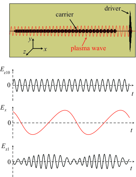
In this article, we show a novel ultrafast all-optical plasma-based modulator that can efficiently modulate the spectrum of intense laser pulses to extreme broad bandwidth. The concept is illustrated in Fig. 1: a linearly-polarized femtosecond intense laser propagates in a sub-mm-scale underdense plasma. The ponderomotive force of the laser pulse drives the plasma electrons out of its path. Because the plasma ions are much heavier (by a fact of at least 1836), they barely move and remain unshielded. The resultant pattern of alternating positive and negative charge-separation fields behind the laser driver is a plasma wave, which has been well-described theoretically Esarey09 and measured experimentally Matlis06 . The wave oscillates at the plasma frequency , where , with the ambient electron plasma density, the permittivity of free space, and and the electron rest mass and charge, respectively. For the purpose of optical modulation, the plasma wave is driven at a moderate amplitude. A picosecond carrier laser pulse (with arbitrary polarization direction) co-propagates behind the drive laser with a delay of several plasma wavelengths. The amplitude and frequency of the carrier are simultaneously modulated by the plasma wave during its propagation, generating a number of significant frequency sidebands spaced by the plasma frequency in the frequency domain. The modulation speed is determined by the plasma frequency , which can be estimated as , e.g., THz for cm-3, which is several orders of magnitude faster than the speed of an EOM. Particle-in-cell (PIC) simulations show that such plasma modulators can sustain a carrier intensity up to W/cm2, which is several orders of magnitude higher than what conventional EOMs can handle.
Because of the ultrafast modulation speed and ultrahigh damage threshold, the plasma optical modulator opens a way to efficiently modulate laser pulses in the high-intensity regime. Such highly modulated intense laser pulses may bring a few new physics and applications associated with intense laser-matter interactions. For example, it may be used to produce strong THz radiation via optical rectification as the laser pulses have bandwidth in the THz range Rice1994 . Another possibility is to produce ultra-bright X-ray sources via laser interaction with atoms Chang1997 , since the modulated spectrum by our plasma modulator has been well extended to the mid-infrared regime Popmin2012 . The highly modulated laser pulse exhibit ultrabroad bandwidth, which can suppress the growth rate of the stimulated Raman scattering (SRS) instability, highly important for laser fusion Thomson74 ; Zhao15 .
Results
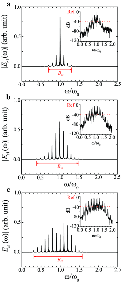
Figure 2 shows an example case to demonstrate the essential features of the modulation obtained from one-dimensional (1D) PIC simulations. For simplicity, the vacuum wavelengths of the two laser pulses are both 1 m in the simulations. In practice, an 800 nm Ti:sapphire femtosecond laser pulse can be used to excite the plasma waves, which does not lead to obvious changes of the results presented in the following. The normalized field amplitudes of the driver and the unmodulated carrier are and , respectively, where , and , with and the light speed and angular frequency in vacuum, respectively. For linear polarization, , with the peak laser intensity and the laser wavelength in vacuum. Thus, and correspond to the laser intensities of W/cm2 and W/cm2, respectively, for 1 m laser wavelength. Detailed parameters are given in the Methods. The modulated pulse can be well-described using the analytical model presented in the Methods. It can be expressed as , where and are the amplitude modulation index and the frequency modulation index, respectively. The mixed amplitude and frequency modulation of a sinusoidal carrier by a simple sinusoidal plasma wave yields a mass of sidebands including both Stokes and anti-Stokes components given by (with a nonzero integer and as a frequency interval). Note that in the quasi-linear () regime, i.e., where the relativistic-electron-mass increase associated with the motion of the plasma electrons can be neglected, the frequency can be calculated as , with the critical plasma density for the corresponding incident laser wavelength . The spectral bandwidth is defined as sideband , where depends upon the amplitude of driver pulse and the plasma density, in addition to the plasma length.
For high fidelity, we only count the significant sidebands with the amplitudes larger than 1 percent (-40 dB) of the amplitude of the unmodulated carrier sideband . Therefore, the spectral bandwidth of the modulated carrier can be calculated by estimating the number of significant sidebands. As shown in Fig. 2, the higher-order sidebands gradually grow with the laser-plasma interaction time. When the carrier beam completely passes through the plasma, the maximum significant sidebands for the anti-Stokes and Stokes components are and , respectively, giving a bandwidth of , accounting for the fact that for . It is also noted that the sideband spectrum of a mixed modulation is asymmetrical due to the superposition of the sideband components of both amplitude and frequency modulations. The simulation results are in good agreement with the prediction of the analytical model given in the Methods. In this example, the amplitude and frequency modulation indices can be estimated sideband as , and , respectively. Note that corresponds to broadband modulation. The energy transmission rate of the carrier through plasma is about 94.3% in this example.
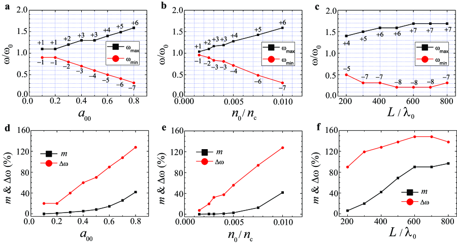
We find the modulation is effective for a wide range of laser-plasma parameters. Figure 3 shows the -40 dB cutoff sidebands, the corresponding fractional bandwidth (), and the amplitude modulation index , as a function of the driver intensity, plasma density and plasma length. When the driver amplitude is relatively small (e.g., ), the modulation is quite weak so that the spectrum only consists of the 1st-order sidebands. By increasing the driver amplitude, the field strength of the plasma wave is enhanced, and subsequently the modulation indices become larger, leading to higher-order sidebands and a wider bandwidth. The similar scaling law exists when increasing the plasma density. Therefore, by properly increasing the driving laser intensity and plasma density, one can extend the spectrum of the modulated carrier to the mid-infrared regime in the low frequency side (or the Stokes waves). We note that the growth of the bandwidth is relatively insensitive to the increase of the plasma length after certain distance, which implies a saturation of modulation. As shown in Fig. 3d-3f, the amplitude modulation index gradually grows with the increase of the driver intensity or the plasma density. When increasing the plasma length, first grows and then saturates at the 100% level, which indicates that the carrier breaks up into a train of short pulses, and each of these short pulses has a width on the order of the plasma wavelength. According to Fig. 3d-3f, and have similar dependence on the driver intensity, the plasma density, and the plasma length as .
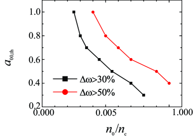
For certain applications, it is important to know the parameter range for broad bandwidth generation. Figure 4 illustrates the parameter range for generating ultrabroad bandwidths (for example, ), which presents a series of simulations where the threshold for the driver amplitude is scanned for a given plasma density . In general, a broader bandwidth can be achieved at a higher plasma density even if a lower driver intensity is adopted.
Discussion
So far we have discussed the spectrum development of the carrier laser pulse as a function of the drive laser amplitude, plasma density, and the plasma length. One question still to be answered is the maximum carrier laser intensity allowed in the plasma modulator. A previous study has shown that the resultant pulse train can amplify the field strength of the plasma wake to a wave breaking level if the initial amplitude of carrier laser intensity is high enough Sheng02 . We also find the remarkably enhanced plasma waves when the intensity of the pulse train is on the same order of the drive intensity (e.g., W/cm2 level). This can result in severe distortion of the plasma wave and considerable energy loss of the carrier laser to plasma wave excitation as well as electron trapping and acceleration (see Supplementary information). As a consequence, the frequency modulation of the carrier laser is suppressed. Therefore, the maximum intensity of the carrier laser should be well below W/cm2 (e.g., at W/cm2 level) in order to realize an excellent performance of the plasma optical modulator.
The maximum allowed pulse duration of the carrier laser for effective modulation may be interesting for some particular applications. This depends upon the life time of the electron plasma waves, which is determined by the collisional damping, Landau damping, and phase mixing Gupta99 ; HXu06 . Typically the initial electron plasma temperature is over 10 eV and the effective is over 100 eV when considering the electron quiver motion in the carrier laser with intensity about W/cm2, which leads to a time scale of over 10 ps for the collisional damping under the plasma electron density of . The Landau damping time is much longer than the collisional damping time in the present case when the plasma wave is driven at moderate amplitudes. The phase mixing due to the ion motion is the key responsibility for the plasma wave decay since it occurs on a much shorter time scale of ps Gupta99 when a high Z gas such as argon is used for the plasma wave generation, where is the normalized amplitude of the plasma wave, with and the ion mass. PIC simulations show that the plasma wave starts to decay around 1.65 ps due to the phase mixing, which is in good agreement with the analytical model. The maximum pulse duration for the effective modulation is around 3 ps for the laser-plasma parameters under consideration (see Supplementary information).
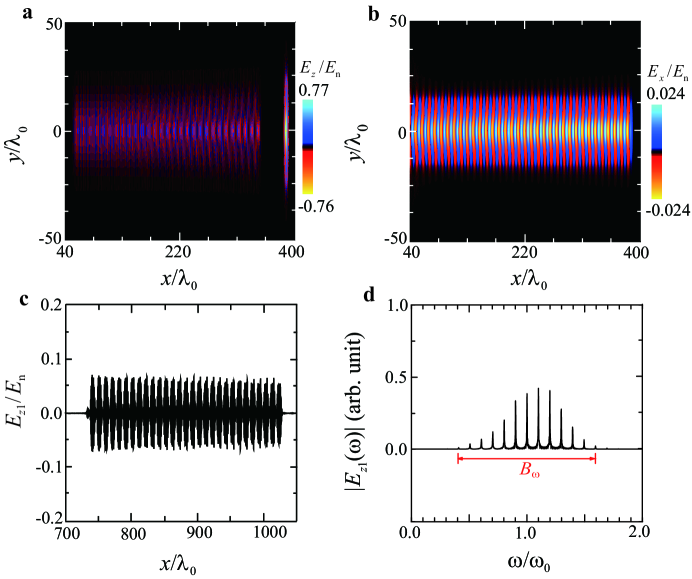
Another issue is the spot sizes of the laser pulses. As we have shown above, the laser pulses need to propagate over a distance about 1 mm without significant transverse spreading. One needs to take relatively large laser spot size so that the corresponding Rayleigh length is long enough. Meanwhile, self-focusing will occur when the driver power exceeds a critical power , with . For linear polarization, Esarey09 . To avoid strong self-focusing within 1 mm, the laser spot size also cannot be too large. Two-dimensional (2D) simulations show that the optimal modulation can be achieved for . An example of 2D simulation is given in Fig. 5. Detailed parameters are given in the Methods. In this example, the driver power is and weak self-focusing occurs during the propagation. As shown in Fig. 5a, the maximum amplitude of the driver increases by 10% (from to 0.77) at a propagation distance of . The excited plasma wave retains the quasi-1D structure, and keeps quite stable during propagation, which is advantageous for the modulation process. It is noted that the driver spot leads to transverse inhomogeneity of the plasma wave, resulting in transverse inhomogeneity of the modulation. By reducing the driver intensity, the corresponding spot size can be increased, and hence, the transverse uniformity of the modulation can be improved. A test experiment can be done with a carrier laser pulse [e.g., Nd:YVO4, 1 m, 15 mJ, 1 ps in the full width at half maximum (FWHM) of the intensity] delayed with respect to a drive laser pulse [e.g., Ti:sapphire, 0.8 m, 70 mJ, 20 fs (FWHM)], co-propagating in a 1-mm-long helium gas with a density of cm-3. The time delay between the two laser pulses, which is relatively flexible, can be controlled in a timescale of hundreds of femtoseconds. Therefore, the plasma optical modulator can be tested experimentally without significant technical difficulties.
In summary, we have illustrated a novel application of the plasma wave as a unique optical modulator for intense lasers. It relies on two co-propagating laser pulses in a short underdense plasma: A driver with a typical intensity W/cm2, which propagates in the plasma and excites a plasma wake, and a carrier, which propagates behind the driver by several plasma wavelengths. Both the amplitude and frequency of the carrier are modulated by the plasma wave, leading to an ultrabroad bandwidth in its spectrum which extends to the mid-infrared range. The modulation speed is in the THz regime. Compared with the low damage threshold of the conventional EOMs, the plasma modulator allows the carrier intensity as high as up to W/cm2. In addition, the plasma modulator offers excellent performance control by changing the driver intensity, the plasma density, and the plasma length. The required experimental conditions for such plasma modulators are within current technical capabilities.
Methods
.1 Mathematical model for mixed-modulation.
Physically, the modulation of the carrier laser pulse by an electron plasma wave is similar to that found for an intense laser propagation in plasma via stimulated Raman forward scattering (coupled with the self-modulation instability) mori1997 ; tzeng1999 . The latter leads to a spectrum of Stokes and anti-Stokes waves when the laser pulse has a duration longer than a plasma wavelength. The evolution of the amount of Stokes/anti-Stokes modes can be described by photon acceleration and deceleration wilks1989 ; esarey1990 ; sheng1993 . The dependence of the spectral modulation on the plasma wave amplitude, plasma density and interaction time discussed in the above section also qualitatively agrees with the previous theories. The difference between the spectral modulation described in the previous theories and here is that our plasma optical modulator enables the spectral modulation of the carrier laser to be well-controlled and to be developed much more efficiently. The frequency modulation due to stimulated Raman forward scattering and self-modulation instabilities can be ignored in our case.
The carrier pulse is modulated in the amplitude and frequency by the electron plasma wave, i.e., a mixed modulation. Its temporal structure can be written asOzimek87
assuming that the excited plasma wave is a simple sinusoidal oscillation, with the normalized axial electric field Esarey09 . Here is the normalized amplitude of the unmodulated carrier. For a linearly-polarized sinusoidal driver with optimal length for plasma wave excitation (i.e., the pulse length approximate to the plasma wavelength), , yielding the amplitude and frequency modulation indices and , respectively. These two parameters also depend upon the interaction time or the plasma length as shown in the simulation results given in Fig. 3. Using simple trigonometrical transformations and a lemma of Bessel functionKreh12 and , can be written as
It is obvious that the spectrum of primarily consists of three components: the central frequency that corresponds to the unmodulated carrier, and the two first-order sidebands resulting from the modulation process. The amplitudes of the frequency components can be characterized by the expansion in a series of th-order Bessel function . By taking Fourier transformation of , and considering the th-order frequency component with a positive integer, we can get the amplitudes of the upper sideband () and the lower sideband () in the spectrum as follows:
for . From the above equations, it is obvious that the amplitude of the lower sideband is not equal to the amplitude of the corresponding upper sideband, resulting in an asymmetrical sideband spectrum. For a weak frequency modulation (), the modulation index is so small that the spectrum essentially consists of and only one set of sidebands , with the amplitudes of , and . For a large modulation index (, there will be a number of significant sidebands spanning over a broad frequency range.
.2 PIC Simulations.
Simulations have been carried out using the code osiris Fonseca02 . In the 1D simulations (e.g., in Fig. 2), the temporal profile of the drive pulse is , with and . The carrier pulse, which is delayed by from the driver, has a duration of . It has a similar profile as the driver at its leading and trailing edges, and a plateau of in between. The amplitudes of the driver and the carrier are , , respectively. The trapezoid-shaped plasma has a length of with a plateau of , located between and . The initial plasma electron density in the plateau region is set to be . For laser-driven plasma waves, typically the initial (photoionized) electron plasma temperature is set to be 10 eV. The simulation box size is with 20 macro-particles per cell. The resolution of the computational grid is . At , the front of the driver enters the simulation box. In the 2D simulation (Fig. 5), the amplitude of the driver is and the spot sizes of the driver and the carrier are and , respectively. The trapezoid-shaped plasma has a length of . Other laser-plasma parameters are the same as the 1D simulations. The simulation box size is with 4 macro-particles per cell. The resolution of the computational grid is and .
References
References
- (1) Liu, K., Ye, C. R., Khan, S. Sorger, V. J. Review and perspective on ultrafast wavelength-size electro-optic modulators. Laser Photonics Rev. 9, 172-194 (2015).
- (2) Reed,G. T., Mashanovich, G., Gardes, F. Y. Thomson, D. J. Silicon optical modulators. Nat. Photon. 4, 518-526 (2010).
- (3) Liu, M. et al. A graphene-based broadband optical modulator. Nature 474, 64-67 (2011).
- (4) Phare, C. T., Lee, Y.-H. D., Cardenas, J. Lipson, M. Graphene electro-optic modulator with 30 GHz bandwidth. Nat. Photon. 9, 511-515 (2015).
- (5) Seeds, A. J. Williams, K. J. Microwave photonics. J. Lightwave Technol. 24, 4628-4641 (2006).
- (6) Capmany, J. Novak, D. Microwave photonics combines two world. Nat. Photon. 1, 319-330 (2007).
- (7) Melikyan, A. et al. High-speed plasmonic phase modulators. Nat. Photon. 8, 229-233 (2014).
- (8) Macario, J. et al. Full spectrum millimeter-wave modulation. Opt. Express 20, 23623-23629 (2012).
- (9) Chen, D. et al. Demonstration of 110 GHz electro-optic polymer modulators. Appl. Phys. Lett. 70, 3335-3337 (1997).
- (10) Huang, H. et al. Broadband modulation performance of 100-GHz EO polymer MZMs. J. Lightwave Technol. 30, 3647-3652 (2012).
- (11) Bryan, D. A., Gerson, R. Tomaschke, H. E. Increased optical damage resistance in lithium niobate. Appl. Phys. Lett. 44, 847-849 (1984).
- (12) Furukawa, Y., Sato, M., Kitamura, K., Yajima, Y. Minakata, M. Optical damage resistance and crystal quality of LiNbO3 single crystals with various [Li]/[Nb] ratios. J. Appl. Phys. 72, 3250-3254 (1992).
- (13) Furukawa, Y. et al. Investigation of bulk laser damage threshold of lithium niobate single crystals by Q-switched pulse laser. J. Appl. Phys. 69, 3372-3374 (1991).
- (14) http://www.newport.com/Electro-Optic-Modulator-Selection-Guide/977460/1033/content.aspx?xcid=bing-ppc-0244
- (15) Paul, A. et al. Quasi-phase-matched generation of coherent extreme-ultraviolet light. Nature 421, 51-54 (2003).
- (16) Thomson, M. D., Kreß, M., Löffler, T. Roskos, H. G. Broadband THz emission from gas plasmas induced by femtosecond optical pulses: From fundamentals to applications. Laser Photon. Rev. 1, 349-368 (2007).
- (17) Chen, Y. et al. Elliptically polarized Terahertz emission in the forward direction of a femtosecond laser filament in air. Appl. Phys. Lett. 93, 231116 (2008).
- (18) Cho, M.-H. et al. Strong terahertz emission from electromagnetic diffusion near cutoff in plasma.New J. Phys. 17, 043045 (2015).
- (19) Esarey, E., Schroeder, C. B. Leemans, W. P. Physics of laser-driven plasma-based electron accelerators. Rev. Mod. Phys. 81, 1229-1285 (2009).
- (20) Glenzer, S. H. et al. Symmetric inertial confinement fusion implosions at ultra-high laser energies. Science 327, 1228-1231 (2010).
- (21) Zhong, J.-Y. et al. Modelling loop-top X-ray source and reconnection outflows in solar flares with intense lasers. Nat. Phys. 6, 984-987 (2010).
- (22) Leemans, W. P. et al. GeV electron beams from a centimetre-scale accelerator. Nat. Phys. 2, 696-699 (2006).
- (23) Leemans, W. P. et al. Multi-GeV electron beams from capillary-discharge-guided subpetawatt laser pulses in the self-trapping regime. Phys. Rev. Lett. 113, 245002 (2014).
- (24) Thaury, C. et al. Plasma mirrors for ultrahigh-intensity optics. Nat. Phys. 3, 424-429 (2007).
- (25) Andreev, A. A. et al. Optimal ion acceleration from ultrathin foils irradiated by a profiled laser pulse of relativistic intensity. Phys. Plasmas 16, 013103 (2009).
- (26) Wu, H.-C., Sheng, Z.-M., Zhang, Q.-J., Cang, Y. Zhang, J. Manipulating ultrashort intense laser pulses by plasma Bragg gratings. Phys. Plasmas 12, 113103 (2005).
- (27) Wang, H.-Y. et al. Laser shaping of a relativistic intense, short Gaussian pulse by a plasma lens. Phys. Rev. Lett. 107, 265002 (2011).
- (28) Trines, R. M. G. M. et al. Simulations of efficient Raman amplification into the multipetawatt regime. Nat. Phys. 7, 87-92 (2011).
- (29) Mourou, G. A., Tajima, T. Bulanov, S. V. Optics in the relativistic regime. Rev. Mod. Phys. 78, 309-371 (2006).
- (30) Yang, X. et al. Chirped pulse Raman amplification in warm plasma: towards controlling saturation. Sci. Rep. 5, 13333 (2015).
- (31) Wen, H., Daranciang, D. Lindenberg, A. M. High-speed all-optical terahertz polarization switching by a transient plasma phase modulator. Appl. Phys. Lett. 96, 161103 (2010).
- (32) Matlis, N. H. et al. Snapshots of laser wakefields. Nat. Phys. 2, 749-753 (2006).
- (33) Rice, A. et al. Terahertz optical rectification from zinc-blende crystals. Appl. Phys. Lett. 64, 1324-1326 (1994).
- (34) Chang, Z., Rundquist, A., Wang, H., Murnane, M. M. Kapteyn, H. C. Generation of coherent soft X rays at 2.7 nm using high harmonics. Phys. Rev. Lett. 79, 2967-2970 (1997).
- (35) Popmintchev, T. et al. Bright coherent ultrahigh harmonics in the keV X-ray regime from mid-infrared femtosecond lasers. Science 336, 1287-1291 (2012).
- (36) Thomson, J. Karush, J. I. Effects of finite-bandwidth driver on the parametric instability. Phys. Fluids 17, 1608-1613 (1974).
- (37) Zhao, Y. et al. Effects of large laser bandwidth on stimulated Raman scattering instability in underdense plasma. Phys. Plasmas 22, 052119(1)-052119(7) (2015).
- (38) http://literature.agilent.com/litweb/pdf/5954-9130.pdf
- (39) Sheng, Z.-M., Mima, K., Sentoku, Y., Nishihara, K. Zhang, J. Generation of high-amplitude plasma waves for particle acceleration by cross-modulated laser wake fields. Phys. Plasmas 9, 3147-3153 (2002).
- (40) Gupta, S. S. Kaw, P. K. Phase mixing of nonlinear plasma oscillations in an arbitrary mass ratio cold plasma. Phys. Rev. Lett. 82, 1867-1870 (1999).
- (41) Xu, H., Sheng, Z.-M. Zhang, J. Phase mixing due to ion motion and relativistic effects in nonlinear plasma oscillations. Phys. Scr. 74, 673 C677 (2006).
- (42) Mori, W. B. The physics of the nonlinear optics of plasmas at relativistic intensities for short-pulse lasers. IEEE J. Quan. Electr. 33, 1942-1953 (1997).
- (43) Tzeng, K.-C., Mori, W. B. Katsouleas T. Self-trapped electron acceleration from the nonlinear interplay between Raman forward scattering, self-focusing, and hosing. Phys. Plasmas 6, 2105-2116 (1999).
- (44) Wilks, S. C., Dawson, J. M., Mori, W. B., Katsouleas, T. Jones, M. E. Photon accelerator, Phys. Rev. Lett. 62, 2600-2603 (1989).
- (45) Esarey, E., Ting, A. Sprangle, P. Frequency shifts induced in laser pulses by plasma waves. Phys. Rev. A 42, 3526-3531 (1990).
- (46) Sheng, Z.-M., Ma, J.-X., Xu, Z.-Z. Yu, W. Effect of an electron plasma wave on the propagation of an ultrashort laser pulse. J. Opt. Soc. Am. B 10, 122-129 (1993).
- (47) Ozimek, E. Sȩk, A. Perception of amplitude and frequency modulated signals (mixed modulation). J. Acoust. Soc. Am. 82, 1598-1603 (1987).
- (48) Kreh, M. Bessel Functions Götingen Summer School on Number Theory 1-21 (2012).
- (49) Fonseca, R. A. et al. OSIRIS, a three-dimensional fully relativistic particle in cell code for modeling plasma based accelerators. Lect. Not. Comput. Sci. 2331, 342-351 (2002).
Acknowledgements
The authors would like to thank Thomas Sokollik, Yulong Tang, Jun Zheng, Yanping Chen, and Guoqiang Xie for useful discussions. This work was supported by the National Basic Research Program of China under Grant No. 2013CBA01500, 2014CB339801 and 2015CB859700, the National Natural Science Foundation of China under Grants No. 11421064, 11405107 and 11475113. Simulations have been carried out on the PI supercomputer at Shanghai Jiao Tong University and the Milky Way 2 supercomputer in the National Supercomputer Center in Guangzhou. We acknowledge the support of the UK EPSRC (grant no. EP/J018171/1) and a Leverhulme Trust Research Project Grant.
Author contributions
L.L.Y. and Z.M.S. designed the overall concept presented in this paper. L.L.Y. carried out all the simulations and the analytical model, and wrote the main manuscript text. Z.M.S., Y.Z., L.J.Q., M.C., S.M.W., D.A.J., W.B.M., and J.Z. contributed to analyze the results and write the manuscript. All authors discussed the results and commented on the manuscript.
Additional information
Supplementary information is available in the online version of the paper. Reprints and permissions information is available online at www.nature.com/reprints. Correspondence and requests for materials should be addressed to L.L.Y. and Z.M.S.
Competing financial interests
The authors declare no competing financial interests.
Figure legends