Experimental Evaluation of Large Scale WiFi Multicast Rate Control
Abstract
WiFi multicast to very large groups has gained attention as a solution for multimedia delivery in crowded areas. Yet, most recently proposed schemes do not provide performance guarantees and none have been tested at scale. To address the issue of providing high multicast throughput with performance guarantees, we present the design and experimental evaluation of the Multicast Dynamic Rate Adaptation (MuDRA) algorithm. MuDRA balances fast adaptation to channel conditions and stability, which is essential for multimedia applications. MuDRA relies on feedback from some nodes collected via a light-weight protocol and dynamically adjusts the rate adaptation response time. Our experimental evaluation of MuDRA on the ORBIT testbed with over 150 nodes shows that MuDRA outperforms other schemes and supports high throughput multicast flows to hundreds of receivers while meeting quality requirements. MuDRA can support multiple high quality video streams, where of the nodes report excellent or very good video quality.
I Introduction
Multimedia (e.g., video) delivery is an essential service for wireless networks and several solutions were proposed for crowded venues [1, 2, 3]. Most of them are based on dense deployments of Access Points (APs) and require considerable capital and operational expenditure, may suffer from interference between APs, and may exacerbate hidden node problems [4, 5]. Multicast offers another approach for video delivery to large groups of users interested in venue specific content (e.g., sports arenas, entertainment centers, and lecture halls). However, WiFi networks provide limited multicast support at a low rate (e.g., Mbps for 802.11a/g) without a feedback mechanism that guarantees service quality. To improve performance, there is a need for a multicast system that dynamically adapts the transmission rate [6]. Yet, designing such a system poses several challenges, as outlined below.
Multicast Rate Adaptation (RA) - Challenges:
A key challenge in designing multicast RA schemes for large groups is
to obtain accurate quality reports with low overhead.
Some systems [7, 8, 9] experimentally demonstrated impressive ability to deliver
video to a few dozen nodes by utilizing Forward Error Correction (FEC) codes
and retransmissions.
However, most approaches do not scale to very large
groups with hundreds of nodes, due to the following:
(i) Most schemes tune the rate to satisfy the receiver with the worst channel condition. As shown in [10, 11]
in crowded venues, a few unpredictable outliers, referred to as abnormal nodes, may suffer from low SNR and Packet Delivery Ratio (PDR) even at the lowest rate and without interference. This results from effects
such as multipath and fast fading [12].
Therefore,
a multicast scheme cannot provide high rate while ensuring reliable delivery to all users.
(ii) It is impractical to continuously collect status reports from all or most users without hindering performance.
Even if feedback is not collected continuously, a swarm of retransmission requests may be sent following an interference event, (wireless interference is bursty [13]) thereby causing additional interruptions.
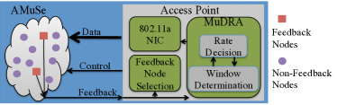
To overcome these challenges, a multicast system should conduct efficient RA based on only limited reports from the nodes. We have been developing the Adaptive Multicast Services (AMuSe) system for content delivery over WiFi multicast. In our recent papers [10], we focused on efficient feedback collection mechanisms for WiFi multicast as part of the AMuSe system. In this paper, we present the Multicast Dynamic Rate Adaptation (MuDRA) algorithm. MuDRA leverages the efficient multicast feedback collection of AMuSe and dynamically adapts the multicast transmission rate to maximize channel utilization while meeting performance requirements. Fig. 1 shows the overall AMuSe system composed of (i) MuDRA algorithm, and (ii) a feedback mechanism. Before describing MuDRA, the overall AMuSe system design, and our contributions in detail, we now first briefly outline the related work relevant to the system design.
I-A Related Work
Unicast RA, multicast feedback schemes, and multicast RA have received considerable attention (see surveys in [14, 15, 16] ).
Unicast RA: We discuss unicast RA schemes, since they can provide insight into the design of multicast RA. In Sampling-based algorithms, both ACKs after successful transmissions and the relation between the rate and the success probability are used for RA after several consecutive successful or failed transmissions [17, 18, 19]. The schemes in [20, 21, 22] distinguish between losses due to poor channel conditions and collisions, and update the rate based on former. Recently, [23, 24] propose multi-arm bandit based RA schemes with a statistical bound on the regret. However, such schemes cannot support multicast, since multicast packets are not acknowledged. In Measurement-based schemes the receiver reports the channel quality to the sender which determines the rate [25, 26, 27, 28, 29, 30, 31]. Most measurement-based schemes modify the wireless driver on the receiver end and some require changes to the standard, which we avoid.
Multicast Feedback Mechanisms:
Solutions for improving multicast service quality are based on collecting feedback from the receivers and adapting the sender rate.
They integrate Automatic Repeat Request (ARQ) mechanisms into the protocol
[32, 33, 34, 8, 35, 36, 37, 38],
add Forward Error Correction (FEC) packets [39, 40, 41, 7], and utilize
RA methods [42, 43, 34, 44].
The feedback mechanisms can be classified into five categories:
(i) Collecting Individual Feedback from all users for each received packet [33, 45, 46, 7, 38, 47, 48]. Although this offers reliability, it does not scale for large groups. The other approaches provide scalability by compromising on the feedback accuracy.
(ii) The Leader-Based Protocol with acknowledgements (LBP-ACK) method
[34, 40, 47, 35, 9]
selects a few receivers to provide feedback,
typically the receivers with the lowest channel quality.
(iii) Pseudo-Broadcast [8, 49, 9]
converts the multicast feed to a unicast flow and sends it to one leader.
The leader acknowledges the reception of the unicast flow while the other receivers receive packets by listening to the channel in promiscuous mode.
(iv) The Leader-Based Protocol with negative acknowledgements (LBP-NACK)
[32, 50, 44] method improves Pseudo-Broadcast by allowing the other receivers to send NACKs for lost packets.
The leader based approaches (ii)-(iv) cannot provide guarantees on the feedback accuracy [38, 10]. Moreover, most LBP-ACK and LBP-NACK methods require changes to the standard.
(v) Cluster-Based Feedback Mechanisms [33, 38, 10, 51] handle the scalability issue by using the fact that adjacent receivers experience similar service quality.
They partition the receivers into clusters and select the receiver
with the weakest channel condition at each cluster as a feedback (FB) node that sends status reports to the sender.
These methods, however, do not guarantee reliable delivery to all receivers.
Additionally, [39, 52, 41] propose to use strong FEC for overcoming losses without specifying any feedback mechanism.
Others [38, 8, 9, 44] balance between the accuracy requirements and low overhead by using a combination of methods (e.g., Pseudo-Broadcast with infrequent reports from the other receivers).
Multicast RA: In [42, 43, 34, 8, 53] the sender uses feedback from leaders (nodes with worst channel conditions) for RA. In [44] when the channel conditions are stable, RA is conducted based on reports of a single leader. When the channel conditions are dynamic, feedback is collected from all nodes. Medusa [9] combines Pseudo-Multicast with infrequent application layer feedback reports from all nodes. The MAC layer feedback sets backoff parameters while application layer feedback is used for RA and retransmissions of video packets. Recently, in [10] we considered multicast to a large set of nodes and provided a rudimentary RA scheme which is not designed to achieve optimal rate, maintain stability, or respond to interference.
I-B Our Contributions
We present a multicast rate adaptation algorithm MuDRA which is designed to support WiFi multicast to hundreds of users in crowded venues. MuDRA can provide high throughput while ensuring high Quality of Experience (QoE). MuDRA benefits from a large user population, which allows selecting a small yet sufficient number of Feedback (FB) nodes with marginal channel conditions for monitoring the quality. We address several design challenges related to appropriate configuration of the feedback level. We note that using MuDRA does not require any modifications to the IEEE 802.11 standard or the mobile devices. We implemented MuDRA with the AMuSe system on the ORBIT testbed [54], evaluated its performance with all the operational IEEE 802.11 nodes (between 150–200), and compared it to other multicast schemes. Our key contributions are:
(i) The need for RA: We empirically demonstrate the importance of RA. Our experiments on ORBIT show that when the multicast rate exceeds an optimal rate, termed as target-rate, numerous receivers suffer from low PDR and their losses cannot be recovered. We also observed that even a controlled environment, such as ORBIT, can suffer from significant interference. These observations constitute the need for a stable and interference agnostic RA algorithm that does not exceed the target-rate.
(ii) Practical method to detect the target-rate: Pseudo-multicast schemes that rely on unicast RA [8] may occasionally sample higher rates and retreat to a lower rate after a few failures. Based on the observation above about the target rate, schemes with such sampling mechanisms will provide low QoE to many users. To overcome this, we developed a method to detect when the system operates at the target-rate, termed the target condition. Although the target condition is sufficient but not necessary, our experiments show that it is almost always satisfied when transmitting at the target-rate. MuDRA makes RA decisions based on the target condition and employs a dynamic window based mechanism to avoid rate changes due to small interference bursts.
(iii) Extensive experiments with hundreds of receivers: Our experiments demonstrate that MuDRA swiftly converges to the target-rate, while meeting the Service Level Agreement (SLA) requirements (e.g., ensuring PDR above to at least of the nodes). Losses can be recovered by using appropriate application-level FEC methods [39, 52, 41, 55, 56].
MuDRA is experimentally compared to (i) pseudo-multicast with a unicast RA [57], (ii) fixed rate, and (iii) a rate adaptation mechanism proposed in [10] which we refer to as Simple Rate Adaptation (SRA) algorithm. MuDRA achieves 2x higher throughput than pseudo-multicast while sacrificing PDR only at a few poorly performing nodes. While the fixed rate and SRA schemes can obtain similar throughput as MuDRA, they do not meet the SLA requirements. Unlike other schemes, MuDRA preserves high throughput even in the presence of interference. Additionally, MuDRA can handle significant node mobility. Finally, we devise a live multicast video delivery approach for MuDRA. We show that in our experimental settings with target rate of Mbps, MuDRA can deliver 3 or 4 high definition H.264 videos (each one of Mbps) where over of the nodes receive video quality that is classified as excellent or good based on user perception.
To summarize, to the best of our knowledge, MuDRA is the first multicast RA algorithm designed to satisfy the specific needs of multimedia/video distribution in crowded venues. Moreover, AMuSe in conjunction with MuDRA is the first multicast content delivery system that has been evaluated at scale. The rest of the paper is organized as follows. Section II describes the ORBIT testbed and important observations. Section III presents the model and objectives. MuDRA’s design is described in Sections IV and V. The experimental evaluation is presented in Section VI before concluding in Section VII.
II Testbed and Key Observations
We evaluate MuDRA on the ORBIT testbed [54], which is a dynamically configurable grid of (400) 802.11 nodes where the separation between nodes is m. It is a good environment to evaluate MuDRA, since it provides a very large and dense population of wireless nodes, similar to the anticipated crowded venues.
Experiments: To avoid performance variability due to a mismatch of WiFi hardware and software, only nodes equipped with Atheros 5212/5213 cards with ath5k driver were selected. For each experiment we activated all the operational nodes that meet these specifications (between and nodes). In all the experiments, one corner node served as a single multicast AP. The other nodes were multicast receivers. The AP used 802.11a to send a multicast UDP flow, where each packet was 1400 bytes. The AP used the lowest supported transmission power of mW dBm to ensure that the channel conditions of some nodes are marginal.

Technical challenges: While analyzing the performance, we noticed that clients disconnect from the AP at high bit-rates, thereby causing performance degradation. This results from the fact that increasing the bit-rate also increases the WiFi beacon bit-rate which may not be decoded at some nodes. A sustained loss of beacons leads to node disconnection. To counter this, we modified the ath5k driver to send beacons at the minimum bit-rate.
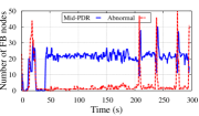
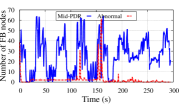
Interference and Stability: We study the time variability of the channel conditions on the ORBIT testbed by measuring the number of nodes with low PDR (below a threshold of ). We call these nodes abnormal nodes (the term will be formally defined in Section III). The number of abnormal nodes out of 170 nodes for rates of and Mbps is shown in Fig. 2. We repeated these experiments several times and observed that even at a low rate, the channel may suffer from sporadic interference events, which cause a sharp increase in the number of abnormal nodes. These interference spikes caused by non-WiFi devices are beyond our control and their duration varies in time.
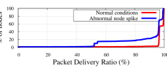
Fig. 3 provides the Cumulative Distribution Function (CDF) of the PDR values with and without sporadic interference. The figure shows that during a spike, over of the nodes suffer from PDR around . Further, the location of the nodes affected by the spikes varies with time and does not follow a known pattern. These experiments show that even in a seemingly controlled environment, nodes may suffer from sporadic continuous interference, which may cause multicast rate fluctuations. Users are very sensitive to changes in video quality [58, 59], and therefore, to keep a high QoE we would like to avoid rate changes due to sporadic interference.
| Symbol | Semantics | Exp. Val. |
|---|---|---|
| Number of nodes associated with the AP. | ||
| Population threshold - Minimal fraction of nodes that should experience high PDR. | ||
| The maximal number of allowed abnormal nodes. | ||
| PDR threshold - Threshold between acceptable (normal) and low (abnormal) PDR. | ||
| Threshold between high PDR and mid-PDR. | ||
| Expected number of FB nodes, . | ||
| Reporting PDR threshold. | ||
| Number of abnormal nodes at time . | ||
| Number of mid-PDR FB nodes at time . | ||
| Minimal RA window size (multiples of reporting intervals). | ||
| Maximal RA window size. |
III Network Model and Objective
We consider a WiFi LAN with multiple APs and frequency planning such that the transmissions of adjacent APs do not interfere with each other. Thus, for RA we consider a single AP with associated users. We assume low mobility (e.g., users watching a sports event). Although we consider a controlled environment, the network may still suffer from sporadic interference, as shown in Section II. The main notation used in the paper is summarized in Table I. Specifically, a PDR-Threshold , is defined such that a node has high QoE if its PDR is above . Such a node is called a normal node. Otherwise, it is considered an abnormal node.
Our objective is to develop a practical and efficient rate control system which satisfies the following requirements:
(R1) High throughput – Operate at the highest possible rate, i.e., the target rate, while preserving SLAs.
(R2) Service Level Agreements (SLAs) – Given (e.g., ), and a Population-Threshold (e.g., ),
the selected rate should guarantee that at least of the nodes experience PDR above (i.e., are normal nodes).
Except for short transition periods, this provides an upper bound of on the
number of permitted abnormal nodes.
(R3) Scalability – Support hundreds of nodes.
(R4) Stability – Avoid rate changes due to sporadic channel condition changes.
(R5) Fast Convergence – Converge fast to the target rate after long-lasting changes (e.g., user mobility or network changes).
(R6) Standard and Technology Compliance –
No change to the IEEE 802.11 standard or operating system of the nodes.
IV Multicast Rate Adaptation
The overall multicast rate adaptation process of MuDRA as a part of the AMuSe system relies on three main components, as illustrated in Fig. 1 and discussed below. We first provide a high level description of each component and then discuss the details in the following subsections.
(i) Feedback (FB) Node Selection: Selects a small set of FB nodes that provide reports for making RA decisions. We describe the FB node selection process in Section IV-A and calculate the reporting interval duration in Section V.111Unlike in unicast where each packet is acknowledged, MuDRA’s reporting intervals are long (in the experiments we consider 2 reports per second).
The following two components compose the MuDRA Algorithm (Algorithm 1). It collects the PDR values from the FB nodes, updates their status (normal or abnormal), invokes the GetRate procedure, which calculates the desired rate, and invokes the GetWinSize procedure, which determines the window size of rate updates (to maintain stability).
(ii) Rate Decision (Procedure 1): Utilizes the limited and infrequent FB reports to determine the highest possible rate, termed the target-rate, while meeting the requirements in Section III. The rate decisions (lines 5–15) rely on rate decision rules that are described in Section IV-B. To maintain rate stability, rate change operations are permitted, only if the conditions for rate change are satisfied for time equal to a window size (determined by the Stability Preserving Method).
(iii) Stability Preserving Method (Procedure 2): A window based method that maintains rate stability in the event of sporadic interference and after an RA decision. It follows the classical Additive Increase Multiplicative Decrease (AIMD) approach. The duration of the time window varies according to the network and channel characteristics (e.g., the typical duration of interference). More details appear in Section IV-C.
IV-A Feedback Node Selection
MuDRA uses a simple and efficient mechanism based on a quasi-distributed FB node selection process, termed -Worst [10], where the AP sets the number of FB nodes and their reporting rates. nodes with the worst channel conditions are selected as FB nodes (the node’s channel condition is determined by its PDR). Hence, the selection process ensures an upper bound on the number of FB messages, regardless of the multicast group size. This upper bound is required for limiting the interference from FB reports, as explained in Section V. The process works as follows: At the beginning of each reporting interval the AP sends a message with a list of or less FB nodes as well as a reporting PDR threshold . is used for adjusting the set of FB nodes to changes due to mobility or variation of the channel condition, i.e., interference222when the system is activated the FB list is empty and .. Upon receiving this message, each FB node waits a short random time for avoiding collisions and then reports its measured PDR to the AP. Every other node checks if its PDR value is below and in such situation it volunteers to serve as an FB node. To avoid a swarm of volunteering messages in the case of sporadic interference, a non FB node verifies that its PDR values are below for three consecutive reporting intervals before volunteering. At the end of a reporting interval, the AP checks the PDR values of all the FB and volunteering nodes, it selects the with lowest PDR values as FB nodes and updates . If the number of selected FB nodes is then for keeping the stability of the FB list, is set slightly below (e.g., ) the highest PDR value of the FB nodes. Otherwise, is set slightly (e.g., ) above the highest PDR value of the FB nodes. The AP sends a new message and the process repeats.
IV-B Rate Decision Rules and Procedure
In this subsection, we describe the target condition which is an essential component of the rate selection rules. Then, we describe the rules and the corresponding Procedure 1.
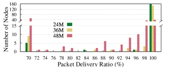
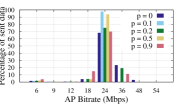
The Target Condition: At a given time, the FB reports are available only for the current rate. To detect the target-rate, most RA schemes occasionally sample higher rates. However, the following experiment shows that this approach may cause undesired disruption to many receivers. We evaluated the PDR distribution of nodes for different multicast transmission rates, denoted as for 3 different experiment runs on different days. Fig. 4 shows the number of nodes in different PDR ranges for values of , , and Mbps for one experiment with nodes. When is at most Mbps, the number of abnormal nodes is very small (at most 5). However, when exceeds Mbps, the PDR of many nodes drops significantly. In this experiment nodes became abnormal nodes which is more than (for ). We observed similar results in other experiments. Thus, in this case, the target rate is Mbps which is the highest rate above which the SLA requirements will be violated. We observed similar results for other experiments as well.
A key challenge is to determine if the AP operates at the target-rate, without FB reports from higher rates. We refer to this assessment as the target condition. Unfortunately, the target-rate cannot be detected from RF measurements, such as SNR. As shown in [60, 61] different nodes may have different receiver sensitivities, which may result in substantial PDR gaps between nodes with similar RF measurements. However, large scale multicast environments enable us to efficiently predict the target condition as described next.
From Fig. 4, we obtain the following important observation.
Observation I: When operating below the target-rate, almost all the nodes have PDR close to . However, when operating at the target-rate, noticeable number of receivers experience PDR below . At Mbps, nodes had PDR below , which is substantially more than .
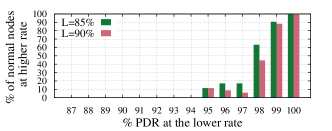
Fig. 5 shows the average percentage of nodes that remain normal vs. their initial PDR when increasing from Mbps to Mbps averaged for 3 different sets of experiments. The total number of nodes in these experiments was . We derive the following observation from Fig. 5.
Observation II: There is a PDR threshold, , such that every node with PDR between and becomes abnormal after the rate increase with very high probability. Note that is the highest threshold for which this observation holds. We refer to these nodes as mid-PDR nodes.
Observation II is not surprising. As reported in [60, 62], each receiver has an SNR band of dB, in which its PDR drops from almost to almost . The SNR of mid-PDR nodes lies in this band. Increasing the rate requires dB higher SNR at the nodes. Hence, mid-PDR nodes with SNR in the transition band before the rate increase will be below or at the lower end of the transition band after the increase, and therefore, become abnormal nodes.
In summary, Observations I and II imply that it is possible to assess the target condition by monitoring the nodes close to transitioning from normal to abnormal. Let and denote the number of abnormal and mid-PDR nodes at time , respectively. We obtain the following empirical property.
Property 1 (Target Condition)
Assume that at a given time , the following condition holds,
| (1) |
then almost surely, the AP transmits on the target-rate at time . This is sufficient but not a necessary condition.
It is challenging to analytically predict when the target condition is satisfied with the available FB information and without a model of the receiver sensitivity of all nodes. However, our experiments show that the target condition is typically valid when operating at the target-rate.
Adjusting the Multicast Rate: The SLA requirement (R2) and target condition (1) give us a clear criteria for changing the rate. The FB scheme only gives us estimates of and , denoted by and respectively. For the -Worst scheme, if ( is a small constant), then and are sufficient to verify if (1) is satisfied because of the following property:
Property 2
If , then, and , where and are the known number of abnormal and mid-PDR known to the AP, and is a small constant. In other words, given that is large enough, the -worst scheme provides accurate estimates of abnormal and mid-PDR nodes.
Proof: First consider the proof for . If , then since and all abnormal nodes must belong in the K FB nodes set. If then all the FB nodes chosen are abnormal and . A similar argument can be made for establishing . If , then . If , then is upper bounded by .
The objective is to choose minimum (for minimum FB overhead) that is sufficient to verify (1). In our experiments, we found that for , works well (Section VI-A). We now derive the following rate changing rules:
Rule I : The system violates the SLA requirement (R2) and the rate is reduced.
Rule II : The system satisfies the target condition.
Rule III : The target condition does not hold and the rate can be increased, under the stability constraints provided in Section IV-C.
In our experiments we use to prevent rate oscillations.
The rate change actions in Procedure 1 are based on the these rules. The flags and indicate whether the multicast rate should be increased or decreased. Rate change operations are permitted only if the time elapsed since the last rate change is larger than the window size determined by the Stability Preserving Method (line 3). The for-loop checks whether the rate should be decreased according to Rule I (line 6) or increased according to Rule II (line 9) for the window duration. Finally, based on the value of the flags and the current rate, the algorithm determines the rate change operation and updates the parameters and , accordingly (lines 10–15).
IV-C The Stability Preserving Method
.
It is desirable to change the rate as soon as Rules I or III are satisfied to minimize QoE disruption (see (R5) in Section III). However, as we show in Fig. 6 such a strategy may cause severe fluctuations of the transmission rate. These result from two main reasons: (i) the reporting mechanism not stabilizing after the last rate change, and (ii) interference causing numerous low PDR reports.
To address this, we introduce in Procedure 2 a window based RA technique which considers the two situations and balances fast convergence with stability. In Procedure 1, rate is changed only if the rate change conditions are satisfied over a given time window, after the last rate change operation (lines 5-9). To prevent oscillations due to short-term wireless channel degradation, when the rate is reduced, the window is doubled in Procedure 2 (line 3). The window size is decreased by when a duration elapses from the last rate or window size change (line 8). This allows recalibrating the window after an atypical long interference episode. The window duration varies between and FB reporting periods. In the experiments, and .
IV-D Handling Losses
MuDRA can handle mild losses (below ) by adding application level FEC [55] to the multicast streams. The PDR-Threshold in our experiments () was selected to allow nodes to handle losses in the event of short simultaneous transmission of another node. In such a situation, the collision probability is below , where is the minimal 802.11 contention window. For 802.11a/g/n , which implies collision probability is below . Therefore, nodes with high PDR (near ) should be able to compensate for the lost packets. If there is strong interference, other means should be used. For instance, the multicast content can be divided into high and low priority flows, augmenting the high priority flow with stronger FEC during the interference period, while postponing low priority flows.
V Reporting Interval Duration
MuDRA relies on status reports from the FB nodes. For immediate response to changes in service quality, the status reports should be sent as frequently as possible, (i.e., minimal reporting interval). However, this significantly impairs the system performance as described below.
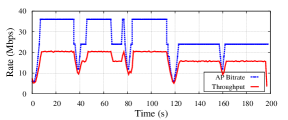
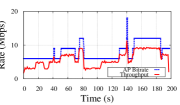
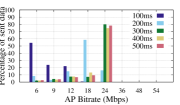
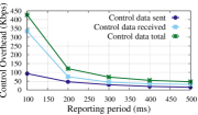
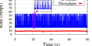
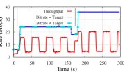
Impact of Aggressive Reporting: Figs. 7-7 show the impact of different reporting intervals on MuDRA . In these experiments, the number of FB nodes () is 50 and the total number of nodes is 158. To focus on RA aspects, we set both and to 5 reporting intervals. Fig. 7 shows that when the reporting interval is too short, MuDRA does not converge to the target rate of Mbps. Fig. 7 shows that in the case of reporting interval of ms, more than 50% of the packets are transmitted at the lowest rate of Mbps. Fig. 7 shows that the control overhead is significantly larger for short reporting intervals (shorter than ms). The control overhead comprises of unicast FB data sent by nodes and multicast data sent by AP to manage FB nodes.
These phenomena result from collisions between feedback reports and multicast messages. In the event of a collision, FB reports, which are unicast messages, are retransmitted, while multicast messages are lost. Frequent reporting increases the collision probability, resulting in PDR reduction and causes the classification of many nodes as mid-PDR nodes, i.e., . Thus, due to Rule II from Section IV-B, the rate is kept close to the minimal rate.
Appropriate Reporting Interval Duration: Assume a greedy AP which continuously transmits multicast messages. We now estimate the PDR reduction, denoted as , for a given reporting interval and upper bound on the number of FB nodes (both normal and abnormal), when the system operates at the low rate of Mbps. In this rate, the transmission duration of multicast and FB messages are ms and ms.
| T (ms) | 100 | 200 | 300 | 400 | 500 | 700 | 1000 |
|---|---|---|---|---|---|---|---|
| 4.69 | 1.56 | 0.94 | 0.67 | 0.52 | 0.36 | 0.25 |
Assume a greedy AP which continuously transmits multicast messages. We now estimate the PDR reduction, denoted as , for a given reporting interval and upper bound on the number of FB nodes (both normal and abnormal), when the system operates at the low rate of Mbps.
Packet Transmission Duration: We denote with and the transmission duration of multicast and feedback report message at the rate of Mbps, respectively. Since the length of each multicast packet is , its transmission duration is ms. Given WiFi overhead of about , we assume ms. The feedback messages are much shorter and we assume that their transmission duration is ms.
Number of feedback reports and multicast messages:
Consider a time interval , say a minute.
The number of feedback reports, denoted as , is
The number of multicast message is given by,
Collision probably of a multicast packet ():
Let us first calculate the number of contention window slots, denoted by , in which packet may be transmitted from the view point of the AP
during the time interval .
Recall that between any two multicast transmissions, the AP waits
an average of half of the contention window size .
This leads to
is the fraction of slots in which both the AP and a FB node send a message. To simplify our estimation, we ignore collisions and retransmission of FB messages333These are second order effects of already low collision probabilities., and assume that in any slots only one FB node may transmit. Therefore,
With proper assignment we get,
| (2) |
| T (ms) | 100 | 200 | 300 | 400 | 500 | 700 | 1000 |
|---|---|---|---|---|---|---|---|
| 4.69 | 1.56 | 0.94 | 0.67 | 0.52 | 0.36 | 0.25 |
VI Experimental Evaluation

For evaluating the performance of MuDRA on
the ORBIT testbed, we use the parameter values listed in Table I.
The performance metrics are described below:
(i) Multicast rate and throughput: The time instants when the target condition is satisfied are marked separately.
(ii) PDR at nodes: Measured at each node.
(iii) Number of abnormal and mid-PDR nodes: We monitored all the abnormal and mid-PDR nodes (not just the FB nodes).
(iv) Control traffic: The feedback overhead (this overhead is very low and is measured in Kbps).
We compared MuDRA to the following schemes:
(i) Fixed rate scheme: Transmit at a fixed rate of Mbps, since it is expected to be the target rate.
(ii) Pseudo-multicast: Unicast transmissions to the node with the lowest SNR/RSS. The unicast RA is the driver specific RA algorithm Minstrel [57]. The remaining nodes are configured in promiscuous mode.
(iii) Simple Rate Adaptation (SRA) algorithm [10]: This scheme also relies on measuring the number of abnormal nodes for making RA decisions. Yet, it is not designed to achieve the target rate, maintain stability, or respond to interference.
VI-A Performance Comparison
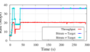
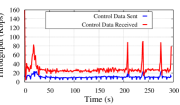
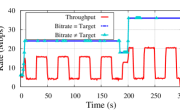
We evaluated the performance of MuDRA in several experiments on different day with nodes. Fig. 8 shows one instance of such an experiment over s with nodes. Fig. 8 shows the mid-PDR and abnormal nodes for the duration of one experiment run. Fig. 8 shows the rate determined by MuDRA . The AP converges to the target rate after the initial interference spike in abnormal nodes at s. The AP successfully ignored the interference spikes at time instants of , , and s to maintain a stable rate. The target-condition is satisfied except during the spikes. The overall control overhead as seen in Fig. 8 is approximately Kbps. The population of abnormal nodes stays around for most of the time which implies that more than nodes () have a PDR . The actual throughput is stable at around Mbps which after accounting for FEC correction implies a goodput of Mbps.
Fig. 9 shows a sample of the throughput and rate performance of the pseudo-multicast scheme. The throughput achieved is close to Mbps. We observe that pseudo-multicast frequently samples higher rates (up to Mbps) leading to packet losses. The average throughput for different schemes over 3 experiments of s each (conducted on different days) with nodes is shown in Table IV. MuDRA achieves 2x throughput than pseudo-multicast scheme. The fixed rate scheme yields approximately higher throughput than MuDRA. SRA has similar throughput as MuDRA .
| No Background traffic | Background traffic | |
|---|---|---|
| Fixed rate = Mbps | 20.42 | 13.38 |
| Pseudo-Multicast | 9.13 | 5.36 |
| MuDRA | 18.75 | 11.67 |
| SRA | 19.30 | 4.55 |
Fig. 9 shows the distribution of average PDR of 162 nodes for the same 3 experiments. In the pseudo-multicast scheme, more than of nodes obtain a PDR close to (we did not consider any retransmissions to nodes listening in promiscuous mode). MuDRA meets the QoS requirements of nodes with at least PDR. On the other hand, in SRA and the fixed rate schemes and of the nodes have PDR less than , respectively.
In pseudo-multicast, more reliable transmissions take place at the cost of reduced throughput, since the AP communicates with the node with the poorest channel quality in unicast. The significant difference in QoS performance of the fixed rate and SRA schemes is because the target rate can change due to interference, etc. In such a situation, MuDRA can achieve the new target rate while the fixed rate and SRA schemes lead to significant losses (we observed that exceeding the target rate even of time may cause up to losses and less than throughput gain).
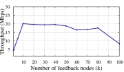
Changing number of FB nodes: We varied the number of FB nodes () between for MuDRA. Fig. 9 shows the throughput as changes. For , MuDRA tunes to the node with the worst channel quality, and consequently, the throughput is very low. On the other hand, increasing from to adds similar amount of FB overhead as decreasing the report interval from ms to ms in Section V. Thus, the throughput decreases for a large number of FB nodes. The throughput for between does not vary significantly which is aligned with our discussion in Section IV that MuDRA needs only for small to evaluate the target rate conditions.
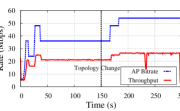
Impact of topology changes: To demonstrate that changes in the network may lead MuDRA to converge to a different rate, we devised a strategy to emulate network topology changes on the grid. During an experiment, a number of FB nodes are turned off at a given time. Since FB nodes have the lowest PDRs, it may lead to changes in the target rate as a large number of nodes with low PDR disappear from the network. Fig. 10 shows the scenario when FB nodes are turned off after s during the experiment. The rate converges quickly and without oscillations to a new target rate of Mbps.
VI-B Impact of Mobility
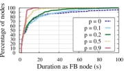
We evaluate MuDRA performance when emulating severe mobility conditions. In the experiments, each node leaves or joins the network with probability after every s. Thus, implies that a node changes its state with probability of approximately % at least once in a minute. Initially, % of the nodes are randomly selected to be in the network.

We conducted 3 experiments consisting of 155 nodes (initially, 77 nodes in on state). Fig. 11 shows the impact of on the distribution of time duration that the nodes remain as FB nodes. Higher values of imply higher mobility and lead to shorter periods for which nodes serve as FB nodes. The average number of changes in FB nodes per second is , , and for equal to , , and , respectively. Even with these changes, the average control overhead is very low (Kbps) and is not affected by the degree of mobility. Fig. 11 shows one instance of the RA process with . We see that MuDRA can adapt to the changing target rate at times , , and s. Fig. 11 shows the percentage of data sent at different rates for several values of averaged over 3 different experiment runs. MuDRA achieves a similar rate distribution for all values of . Our experiments show that MuDRA can achieve the target rate, maintain stability, and adds low overhead, even under severe mobility.
VI-C Impact of External Interference
We envision that MuDRA will be deployed in environments where the wireless infrastructure is centrally controlled. However, in-channel interference can arise from mobile nodes and other wireless transmissions. In addition to the uncontrolled interference spikes on ORBIT, we evaluate the impact of interference from a nearby node which transmits at the same channel as the multicast AP. We consider a scenario with two nodes near the center of the grid that exchange unicast traffic at a fixed rate of Mbps in a periodic on/off pattern with on and off periods s each. The transmission power of the interfering nodes is also dBm. This helps us evaluate the performance in the worst case scenario of continuous interference and study the dynamics of changing interference.
Fig. 12 shows the mid-PDR and abnormal nodes and Fig. 12 shows the rate and throughput for one experiment with nodes. The number of mid-PDR nodes increases during the interference periods, due to losses from collisions. MuDRA converges to the target rate of Mbps. Notice during interference periods, MuDRA satisfied the target-condition and that using the stability preserving method, MuDRA manages to preserve a stable rate. The average throughput of different schemes with on/off background traffic for 3 experiments of s each is in Table IV. Pseudo-multicast achieves half while SRA has a third of the throughput of MuDRA. The fixed rate scheme achieves similar throughput as MuDRA.
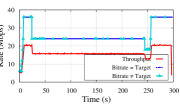
The PDR distribution of nodes is in Fig. 12. MuDRA satisfies QoS requirements while maintaining high throughput. Pseudo-multicast scheme has nodes with PDR more than since it makes backoff decisions from unicast ACKs. SRA yields nodes with PDR less than as it transmits at low rates. The fixed rate scheme yields nodes with PDR less than . The fixed rate scheme performs better than SRA since it maintains a higher rate. We also investigate the combined impact of both interference and mobility, where every s, the probability of a node switching on/off is . Fig. 13 shows the rate and throughput for this case. Similar to results in Section VI-B, the performance of the system is not affected by node mobility.
VI-D Video multicast
We demonstrate the feasibility of using MuDRA for streaming video. The video is segmented with segment durations equal to the period of rate changes (s) and each segment is encoded at several rates in H.264 format. For each time period, the key (I) frames are transmitted reliably at the lowest rate Mbps (note that transmitting the key frames can be achieved with reliability even at Mbps on the testbed). The non-key (B and P) frames are transmitted at the rate set by MuDRA .
Let the multicast rate for current time period be ,the expected data throughput at this rate be , and the estimated throughput at the minimum rate be . Let be the fraction of key frame data and be the fraction of non-key frame data. The video server has to determine the video rate at each time . Let the fraction of transmission time for key frames and fraction of transmission time for non-key frames . We know that
The video rate can be calculated by solving linear equations . In environments where estimates of throughput are inaccurate due to interference, techniques such as in [63] can be utilized.
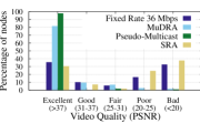
Experimental Results: We use raw videos from an online dataset [64] and encode the videos with H.264 standard. In our data sets, is . For MuDRA with throughput Mbps and FEC correction of , we can support a video rate of Mbps, which is sufficient for 3 or 4 HD streams (each Mbps) on mobile devices. For each node, we generated the video streams offline by mapping the video frames to the detailed packet traces collected on ORBIT from an RA experiment. In our experiments, we only considered a single video stream of rate . For a fair comparison, the I frames were transmitted at Mbps for all schemes. We measured the PSNR of the video at each node and classified the PSNR in 5 categories based on visual perception.
Fig. 14 shows the video quality and PSNR ranges at the nodes for 3 experiments each of s and with nodes. With MuDRA, more than of the nodes achieve excellent or good quality, achieve fair quality, and less than get poor or bad quality. While the pseudo-multicast scheme results in almost all nodes obtaining excellent quality, the video throughput for this scheme is significantly lower (Mbps). SRA and the fixed rate schemes have more than nodes with poor or bad video quality.
VII Conclusion and Future Work
We designed a novel multicast rate adaptation algorithm (MuDRA) that provides high throughput while satisfying SLA requirements. MuDRA’s performance on the ORBIT testbed with hundreds of nodes shows that it can reliably support applications such as large scale multimedia content delivery. In future work, we will refine MuDRA by distinguishing between losses due to channel conditions and collisions.
VIII Acknowledgements
The authors express their gratitude to Ivan Seskar from WINLAB (Rutgers University) for his support in conducting experiments on the ORBIT testbed and several useful technical discussions. This work was supported in part by NSF grant CNS-10-54856, CIAN NSF ERC under grant EEC-0812072, and the People Programme (Marie Curie Actions) of the European Union’s Seventh Framework Programme (FP7/20072013) under REA grant agreement no. [PIIF-GA-2013-629740].11.
References
- [1] Y. Tanigawa, K. Yasukawa, and K. Yamaoka, “Transparent unicast translation to improve quality of multicast over wireless LAN,” in IEEE CCNC’10, 2010.
- [2] “Cisco, white-paper, Cisco connected stadium Wi-Fi solution,” 2011. [Online]. Available: http://www.cisco.com/web/strategy/docs/sports/c78-675063_dSheet.pdf
- [3] “Yinzcam,” http://www.yinzcam.com/.
- [4] K. Pelechrinis, T. Salonidis, H. Lundgren, and N. Vaidya, “Experimental characterization of 802.11n link quality at high rates,” in ACM WiNTECH’10, 2010.
- [5] N. Hajlaoui and I. Jabri, “On the performance of IEEE 802.11n protocol,” in ACM WiNTECH’12, 2012.
- [6] C. Perkins and M. McBride, “Multicast WiFi problem statement,” Working Draft, IETF Internet-Draft, 2015, http://www.ietf.org/internet-drafts/draft-mcbride-mboned-wifi-mcast-problem-statement-00.txt.
- [7] M. Wu, S. Makharia, H. Liu, D. Li, and S. Mathur, “IPTV multicast over wireless LAN using merged hybrid ARQ with staggered adaptive FEC,” IEEE Trans. Broadcast., vol. 55, no. 2, pp. 363 –374, 2009.
- [8] R. Chandra, S. Karanth, T. Moscibroda, V. Navda, J. Padhye, R. Ramjee, and L. Ravindranath, “DirCast: a practical and efficient Wi-Fi multicast system,” in IEEE ICNP’09, 2009.
- [9] S. Sen, N. K. Madabhushi, and S. Banerjee, “Scalable WiFi media delivery through adaptive broadcasts,” in USENIX NSDI’10, 2010.
- [10] Y. Bejerano, J. Ferragut, K. Guo, V. Gupta, C. Gutterman, T. Nandagopal, and G. Zussman, “Scalable WiFi multicast services for very large groups,” in IEEE ICNP’13, 2013.
- [11] K. Papagiannaki, M. Yarvis, and W. S. Conner, “Experimental characterization of home wireless networks and design implications,” in IEEE INFOCOM’06, 2006.
- [12] T. S. Rappaport, Wireless Communication Principle and Practice, 2nd edition. Prentice Hall, 2002.
- [13] D. Aguayo, J. Bicket, S. Biswas, G. Judd, and R. Morris, “Link-level measurements from an 802.11b mesh network,” ACM SIGCOMM’04, 2004.
- [14] D. Nguyen and J. Garcia-Luna-Aceves, “A practical approach to rate adaptation for multi-antenna systems,” in IEEE ICNP’11, 2011.
- [15] R. Combes, A. Proutiere, D. Yun, J. Ok, and Y. Yi, “Optimal rate sampling in 802.11 systems,” arXiv preprint, 2013.
- [16] J. Vella and S. Zammit, “A survey of multicasting over wireless access networks,” IEEE Commun. Surveys Tuts., vol. 15, no. 2, pp. 718–753, 2013.
- [17] A. Kamerman and L. Montebani, “WaveLAN-ii: a high-performance wireless LAN for the unlicensed band,” Bell Labs technical journal, vol. 2, no. 3, p. 118–133, 1997.
- [18] M. Lacage, M. Manshaei, and T. Turletti, “IEEE 802.11 rate adaptation: a practical approach,” in ACM MSWiM’04, 2004.
- [19] J. Bicket, “Bit-rate selection in wireless networks,” PhD thesis, MIT, 2005.
- [20] Q. Pang, V. Leung, and S. Liew, “A rate adaptation algorithm for IEEE 802.11 WLANs based on MAC-layer loss differentiation,” in IEEE BroadNets’06, 2006.
- [21] S. Wong, H. Yang, S. Lu, and V. Bharghavan, “Robust rate adaptation for 802.11 wireless networks,” in ACM MOBICOM’06, 2006.
- [22] J. Kim, S. Kim, S. Choi, and D. Qiao, “CARA: collision-aware rate adaptation for IEEE 802.11 WLANs,” in IEEE INFOCOM’06, 2006.
- [23] B. Radunovic, A. Proutiere, D. Gunawardena, and P. Key, “Dynamic channel, rate selection and scheduling for white spaces,” in ACM CONEXT’11, 2011.
- [24] R. Combes, A. Proutiere, D. Yun, J. Ok, and Y. Yi, “Optimal rate sampling in 802.11 systems,” in IEEE INFOCOM’14, 2014.
- [25] G. Holland, N. Vaidya, and P. Bahl, “A rate-adaptive mac protocol for multi-hop wireless networks,” in ACM MOBICOM’01, 2001.
- [26] S. Rayanchu, A. Mishra, D. Agrawal, S. Saha, and S. Banerjee, “Diagnosing wireless packet losses in 802.11: Separating collision from weak signal,” in IEEE INFOCOM’08, 2008.
- [27] G. Judd, X. Wang, and P. Steenkiste, “Efficient channel-aware rate adaptation in dynamic environments,” in ACM MobiSys’08, 2008.
- [28] M. Vutukuru, H. Balakrishnan, and K. Jamieson, “Cross-layer wireless bit rate adaptation,” in ACM SIGCOMM’09, 2009.
- [29] H. Rahul, F. Edalat, D. Katabi, and C. Sodinii, “Frequency-aware rate adaptation and MAC protocols,” in ACM MOBICOM’09, 2009.
- [30] R. Crepaldi, J. Lee, R. Etkin, S.-J. Lee, and R. Kravets, “CSI-SF: Estimating wireless channel state using CSI sampling and fusion,” in IEEE INFOCOM’12, 2012.
- [31] L. Deek, E. Garcia-Villegas, E. Belding, S.-J. Lee, and K. Almeroth, “Joint rate and channel width adaptation in 802.11 MIMO wireless networks,” in IEEE SECO3’13, 2013.
- [32] J. K. Kuri and S. Kumar, “Reliable multicast in multi-access wireless LANs,” ACM/Kluwer Wirel. Netw., vol. 7, pp. 359–369, 2001.
- [33] M.-T. Sun, L. Huang, A. Arora, and T.-H. Lai, “Reliable MAC layer multicast in IEEE 802.11 wireless networks,” in IEEE ICPP’02, 2002.
- [34] J. Villalon, P. Cuenca, L. Orozco-Barbosa, Y. Seok, and T. Turletti, “Cross-layer architecture for adaptive video multicast streaming over multirate wireless LANs,” IEEE J. Sel. Areas Commun., vol. 25, no. 4, pp. 699 –711, 2007.
- [35] N. Choi, Y. Seok, T. Kwon, and Y. Choi, “Leader-based multicast service in IEEE 802.11v networks,” in IEEE CCNC’10, 2010.
- [36] Z. Li and T. Herfet, “BLBP: a beacon-driven leader based protocol for MAC layer multicast error control in wireless LANs,” in IEEE WiCOM’08, 2008.
- [37] V. Srinivas and L. Ruan, “An efficient reliable multicast protocol for 802.11-based wireless LANs,” in IEEE WoWMoM’09, 2009.
- [38] X. Wang, L. Wang, Y. Wang, Y. Zhang, and A. Yamada, “Supporting MAC layer multicast in IEEE 802.11n: Issues and solutions,” in IEEE WCNC’09, 2009.
- [39] E. Park, S. Han, H. Kim, K. Son, and L. Jing, “Efficient multicast video streaming for IPTV service over WLAN using CC-FEC,” in IEEE ICICSE’08, 2008.
- [40] O. Alay, T. Korakis, Y. Wang, and S. Panwar, “Dynamic rate and FEC adaptation for video multicast in multi-rate wireless networks,” ACM Mobile Netw. and Appl., vol. 15, no. 3, pp. 425–434, 2010.
- [41] H.-T. Chiao, S.-Y. Chang, K.-M. Li, Y.-T. Kuo, and M.-C. Tseng, “WiFi multicast streaming using AL-FEC inside the trains of high-speed rails,” in IEEE BMSB’12, 2012.
- [42] Y. Seok and Y. Choi, “Efficient multicast supporting in multi-rate wireless local area networks,” in IEEE ICOIN’03, 2003.
- [43] A. Basalamah, H. Sugimoto, and T. Sato, “Rate adaptive reliable multicast MAC protocol for WLANs,” in IEEE VTC’06, 2006.
- [44] W.-S. Lim, D.-W. Kim, and Y.-J. Suh, “Design of efficient multicast protocol for IEEE 802.11n WLANs and cross-layer optimization for scalable video streaming,” IEEE Trans. Mobile Comput., vol. 11, no. 5, pp. 780 –792, 2012.
- [45] X. Wang, L. Wang, and D. Wang, Y.and Gu, “Reliable multicast mechanism in WLAN with extended implicit MAC acknowledgment,” in IEEE VTC’08, 2008.
- [46] V. Srinivas and L. Ruan, “An efficient reliable multicast protocol for 802.11-based wireless LANs,” in IEEE WoWMoM’09, 2009.
- [47] Z. Feng, G. Wen, C. Yin, and H. Liu, “Video stream groupcast optimization in WLAN,” in IEEE ITA’10, 2010.
- [48] “IEEE draft standard for information technology telecommunications and information exchange between systems local and metropolitan area networks - specific requirements, part 11: Wireless LAN medium access control (MAC) and physical layer (PHY) specifications - amendment: MAC enhancements for robust audio video streaming,” IEEE, July 2011.
- [49] Y. Park, C. Jo, S. Yun, and H. Kim, “Multi-room IPTV delivery through pseudo-broadcast over IEEE 802.11 links,” in IEEE VTC’10, 2010.
- [50] Z. Li and T. Herfet, “HLBP: a hybrid leader based protocol for MAC layer multicast error control in wireless LANs,” in IEEE GLOBECOM’08, 2008.
- [51] Y. Bejerano, J. Ferragut, K. Guo, V. Gupta, C. Gutterman, T. Nandagopal, and G. Zussman, “Experimental evaluation of a scalable WiFi multicast scheme in the ORBIT testbed,” in 3rd GENI Research and Educational Experiment Workshop (GREE), 2014.
- [52] V. Sgardoni, M. Sarafianou, P. Ferre, A. Nix, and D. Bull, “Robust video broadcasting over 802.11a/g in time-correlated fading channels,” IEEE Trans. Consum. Electron., vol. 55, no. 1, pp. 69–76, 2009.
- [53] K. Lin, W. Shen, C. Hsu, and C. Chou, “Quality-differentiated video multicast in multi-rate wireless networks,” IEEE Trans. Mobile Comput., vol. 12, no. 1, pp. 21–34, January 2013.
- [54] “ORBIT testbed,” http://orbit-lab.org/.
- [55] K. N. D. Vukobratovic, “A survey on application layer forward error correction codes for IP datacasting in DVB-H,” in 3rd COST 2100 MCM, 2007.
- [56] J. Ababneh and O. Almomani, “Survey of error correction mechanisms for video streaming over the internet,” in IJACSA, vol. 5, 2014, pp. 155–161.
- [57] “Minstrel,” https://wireless.wiki.kernel.org/en/developers/documentation/mac80211/ratecontrol/minstrel.
- [58] N. Cranley, P. Perry, and L. Murphy, “User perception of adapting video quality,” Int. J. Hum. Comput. St., vol. 64, no. 8, pp. 637–647, 2006.
- [59] A. Balachandran, V. Sekar, A. Akella, S. Seshan, I. Stoica, and H. Zhang, “A quest for an internet video quality-of-experience metric,” in ACM HotNets’12, 2012.
- [60] C. Reis, R. Mahajan, M. Rodrig, D. Wetherall, and J. Zahorjan, “Measurement-based models of delivery and interference in static wireless networks,” in ACM SIGCOMM’06, 2006.
- [61] D. Halperin, W. Hu, A. Sheth, and D. Wetherall, “Predictable 802.11 packet delivery from wireless channel measurements,” in ACM SIGCOMM’10, 2010.
- [62] M. R. Souryal, L. Klein-Berndt, L. E. Miller, and N. Moayeri, “Link assessment in an indoor 802.11 network,” in IEEE WCNC’06, 2006.
- [63] G. Tian and Y. Liu, “Towards agile and smooth video adaptation in dynamic http streaming,” in ACM CONEXT’12, 2012.
- [64] “Video dataset,” https://media.xiph.org/video/derf/.