Polarization Sensitive Array Based Physical-Layer Security
Abstract
We propose a framework exploiting the polarization sensitive array (PSA) to improve the physical layer security of wireless communications. Specifically, the polarization difference among signals is utilized to improve the secrecy rate of wireless communications, especially when these signals are spatially indistinguishable. We firstly investigate the PSA based secure communications for point-to-point wireless systems from the perspectives of both total power minimization and secrecy rate maximization. We then apply the PSA based secure beamforming designs to relaying networks. The secrecy rate maximization for relaying networks is discussed in detail under both the perfect channel state information and the polarization sensitive array pointing error. In the later case, a robust scheme to achieve secure communications for relaying networks is proposed. Simulation results show that the proposed PSA based algorithms achieve lower total power consumption and better security performance compared to the conventional scalar array designs, especially under challenging environments where all received signals at destination are difficult to distinguish in the spatial domain.
Index Terms:
Physical layer security, polarization sensitive arrays, point-to-point wireless systems, relaying networksI Introduction
The issue of information security in wireless networks has attracted extensive attention in recent years considering the openness of wireless links [1, 2]. Traditionally, encryption techniques are utilized to ensure secure communications, which are generally applied in the upper layer of network and have a high design complexity [3]. Therefore, an intrinsic approach exploring the characteristics of wireless fading channels to improve information security emerges as a prominent technique, which is referred to as the physical layer security [4]. The fundamental theory for physical layer security was firstly established by Shannon [5]. Following Shannon’s work, Wyner [6] introduced the famous wiretap channel model and further defined the channel secrecy capacity. The work [7] proposed a Gaussian degraded wiretap channel which is widely used to model the wireless propagation environment.
Based on these pioneering theoretical concepts, a large amount of literature focusing on various design aspects of secure communications have sprung up. By applying multiple antennas at communication nodes to exploit spatial freedom, these researches aimed to significantly improve the physical layer security of wireless networks [8, 9, 10, 11]. For example, an artificial noise scheme was proposed for wiretap channels in [8] to study the impact of antenna selection on security performance of multi-input multi-output (MIMO) two-way relaying networks. The work [9] introduced an effective method called cooperative jamming to confuse the eavesdropper deliberately. With the aid of the game theory, a collaborative physical-layer security transmission scheme was designed in [10] to effectively balance the security performance among different links. All these works however assume that the wireless channels are ideally Rayleigh distributed, which ignores the influence of array directivity and correlation. A technique known as the directional modulation was also investigated to realize secure communications. In the work [12], the directional modulation technique was applied to the phased array to offer security. Specifically, by shifting each array element’s phase appropriately, the desired symbol phase and amplitude in a given direction is generated. The study [13] on the other hand adopted the directional modulation technique to enhance the security of multi-user MIMO systems. Different from the standard secrecy rate optimization, the secure communications of multi-user MIMO systems are achieved by increasing the symbol error rate at the eavesdropper. It can be seen that the directional modulation technique designs the weighting coefficients of the phased array. As will be shown, our polarization sensitive array (PSA) based technique designs the spatial pointing of each antenna to effectively extract the signals’ polarization information for realizing secure communications.
Generally, the polarization status, similar to the amplitude and phase, is a feature of the signal. Many researches have indicated that the direction-finding performance and short-wave communication quality can be improved by means of the polarization difference among signals [14]. However, in many practical communication scenarios, such as radar and electronic reconnaissance, the conventional scalar array (CSA) is widely deployed. In essence, the CSA is the uniformly spaced linear array with the same spatial properties in all its array elements. Generally, CSA is blind to the polarization status of signal and sensitive to the array aperture and signal wavelength [15]. Worse still, in some specific array alignment, a CSA may present the morbid response to the polarization status of signal. Different from the CSA, the PSA consists of a certain number of antennas with different spatial pointings, which can be utilized to extract the signal information more meticulously and comprehensively in a vector way [16, 17]. The spatial pointings of the PSA offer extra design degrees of freedom for physical layer security of wireless networks. In most practical wireless networks, jammer is typically introduced to effectively interfere with the eavesdropper, but it simultaneously causes the interference to the destination. When the jammer signal has approximately the same spatial properties as the source, the CSA based destination beamforming optimization is unable to suppress the interference, as it can only rely on the signals’ spatial characteristics. By contrast, since different polarization information can be extracted by the spatial pointings of PSA, the PSA based destination beamforming optimization is capable of suppressing the interference effectively, even when the signals are indistinguishable in the spatial domain. Therefore, utilizing the PSA to realize secure communications for wireless networks can achieve superior performance over the CSA design.
However, most existing PSA related works focus on the problem of estimating the signal’s direction of arrival (DOA). In [18], a two-step maximum-likelihood signal estimation procedure was developed under the PSA. Based on the sparse polarization sensor measurements, the DOA estimation of the transmitted signal was conducted in [19]. There also exist some works specifically related to the optimization of dual-polarization array to enhance the system capacity. Compared to the single polarization array, the orthogonal dual polarization antenna can enhance MIMO spatial multiplexing gain remarkably by means of the eigenvalue ratio decomposition [20]. The study [21] designed a linear-polarized dual-polarization frequency reuse system to increase spectrum utilization and further improve the system capacity, while the work [22] compared three different transmission schemes for MIMO networks to achieve the maximum diversity under a dual-polarization channel model. All these works do not consider utilizing PSA to enhance secure communications.
Against the above background, this paper investigates the PSA based secure transmission strategy for wireless networks. Specifically, we first consider the PSA based secure communications for the point-to-point single-input multi-output (SIMO) network with the aid of jammer. In this case, the secure beamforming is firstly designed aiming at minimizing the total transmit power subject to the secrecy rate requirements. Then the secrecy rate maximization scheme is proposed to improve the secrecy capacity of SIMO network as much as possible. Further extending our research into the more complicated scenario where the relay is employed to enlarge the communication coverage of source nodes, we consider the secrecy rate maximization under both perfect channel state information (CSI) and imperfect PSA pointing, respectively. It is worth noting that convex optimization techniques [23] can be utilized to solve the optimization problems formulated in this paper effectively.
The rest of the paper is organized as follows. In Section II, the system model of PSA is briefly introduced. In Section III, the point-to-point secrecy beamforming is designed for SIMO networks, while the one-way relaying network is considered in Section IV, where the corresponding secrecy rate optimization problems are formulated. Section V presents the simulation results, and our conclusions are given in Section VI.
The normal-faced lower-case letters denote scalars, while bold-faced lower-case and upper-case letters stand for vectors and matrices, respectively. denotes the absolute value and denotes the Euclidean norm, while , , and represent the conjugate, transpose, conjugate transpose and inverse operators, respectively. An optimal solution is marked by ⋆, while and denote the trace and rank of matrix, respectively. The th row of matrix is given by , and the th-row and th-column element of is . means that is a positive semidefinite matrix. The vector stacking operator stacks the columns of a matrix on top of one another, and is the diagonal matrix with the diagonal elements . is the identity matrix, and is the matrix with all zero elements. means that is a complex Gaussian distributed random vector with the zero mean vector and the covariance matrix , while is the expectation operator. The determinant operation is denoted by , and denotes the Kronecker product. Finally, , and .
(a) (b)
II Polarization Sensitive Array System Model
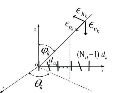
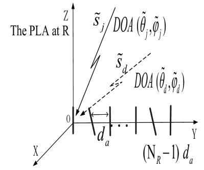
Without loss of generality, we assume that a total of antennas are located in the -axis and the distance between the adjacent antennas is half wavelength, as illustrated in Fig. 1 (a). Here two plane electromagnetic (EM) signals are considered, i.e., the desired EM signal and the jamming EM signal . They arrive at the antennas of the PSA from different incident angles. As is well known, the EM wave is traveling in a single direction, where the electric component and the magnetic component are perpendicular to each other as well as perpendicular to this propagation direction. Taking the electric component as an example, we define the transverse electric field vectors of the EM signal as
| (1) |
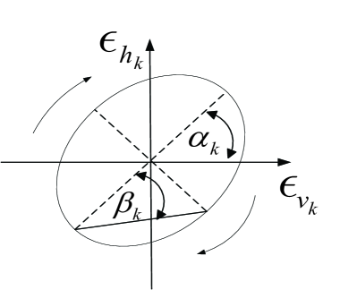
where and are the electric field projections on the and directions, respectively. As a result, the magnetic field biases of the EM signal are and , respectively, for keeping the orthogonality [24]. Furthermore, it is assumed that the EM signals are completely polarized signals which means that the time varying and can be formulated as an ellipse. As described in Fig. 1 (b), and are the polarization orientation and ellipse angle, respectively, which represent the track of the EM signal’s electric vector and are thereafter called the POA for short. According to the EM theory [24, 19, 20, 21, 22, 25, 26], we can express the EM signal in a vector form with its DOA and POA as follows
| (2) |
where and are the azimuth and elevation angles of the EM signal , respectively, while
| (11) |
| (16) |
is the steering matrix of , which is composed of the electric and magnetic field bases of the EM signal, while and are the corresponding rotation and ellipticity matrix of , respectively, [26].
In addition to the polarization of EM signals, the antenna polarization should also be considered. It is noted that only short dipole antennas are adopted in our work, and thus the array magnetic response can be neglected. Besides, the polarization sensitive matrix which represents the polarization characteristics of the array is defined by the spatial pointing angles of the antennas of the PSA, i.e., for , where and are the azimuth and elevation pointing angle of the th antenna of the PSA, respectively. Mathematically, we have
| (21) |
with
| (28) |
where (generally taking the value of 1) is the antenna gain when the polarization status of the EM signal perfectly matches the antenna. Note that the matrix included in indicates that the array magnetic response is ignored. In addition, for the matrix , we have
| (29) |
It is worth emphasizing that different from [19], where the PSA consists of the aligned short dipole antennas, each antenna of the PSA in our paper is deployed with a different spatial pointing angle, which becomes an optimization variable for secure communications.
Furthermore, the space phase matrix of the EM signal impinging on the PSA is given by
| (30) | ||||
| (31) |
where denotes the propagation vector of the EM signal , is the position vector of the th polarization antenna, and is the wavelength of . Based on (2), (21) and (30), the spatio-polarized manifold for the EM signal is defined as
| (32) |
for . For notational convenience, we will simplify as in the sequel.
For the sake of maximizing secrecy rate, the PSA’s spatial pointings need to be optimized. In order to perform this optimization conveniently, the formulation (32) is rewritten as
| (33) |
for , where
| (34) | ||||
| (35) |
Clearly, the new vector denotes the PSA’s spatial pointings and thus becomes our optimization variables.
III Point-to-Point Secrecy Beamforming Design
We consider the simplest but most representative wiretap channel as a source, a destination and an eavesdropper. In most cases, the capacity of the wiretap channel is higher than the main channel owing to the concealment and intention of the eavesdropper. In order to realize secure communications, we introduce a jammer to disturb the eavesdropper sufficiently. In this four-terminal network as depicted in Fig. 2, the source and jammer are equipped with single antenna, while the eavesdropper and the destination are equipped with and antennas, respectively. More importantly, in our work, the -antenna PSA at destination is assumed instead of the conventional CSA to fully show the advantage of PSA for secure communications 111Our work can easily be extended to the more general case, where the eavesdropper is also equipped with the PSA of antennas. In fact, in this case, all our designs and algorithms remains applicable and effective. Due to the space limitation, the detailed discussions are omitted here..
| (18) |
Let be the channel gain vector from node to node , where and . Furthermore, we assume far field communications related to destination , and we denote and as the channel gains from source and jammer to the reference antenna (the first antenna) of the PSA at destination , respectively. It is worth pointing out that the eavesdropper in our work is a legitimate, active but non-intended receiver, which means that can simultaneously transmit signals to other nodes and intercept the confidential signal from source. Based on this assumption, the CSI of eavesdropper is available through a training-based channel estimation technique. For the sake of improving security performance of the SIMO network, a beamforming vector satisfying is applied to the antennas of the PSA to maximize the received confidential signal to interference plus noise ratio (SINR). Based on this setting, source and jammer simultaneously transmit the confidential signal and the jammer signal to the destination and eavesdropper , respectively. Here, is assumed. Since and are far field signals relative to the PSA, the signals and impinging on the reference antenna of the PSA from source and jammer are represented as and , respectively, where and denote the maximum transmit powers of source and jammer , respectively.
| (31) |
Because both source and jammer are far-field narrowband synchronized transmitters 222Synchronizing the transmissions of source and jammer is important. To achieve the synchronization between two transmitters, one of the transmitters can serve as master and the other as slave, see for example [27]. In our case, the source serves as the master, who broadcasts the carrier and timing signals, while the jammer acts as the slave, who locks up to the carrier and timing signals from the master. In this way, the jammer acquires the carrier frequency and phase as well as achieves the timing synchronization with the source., the change of the complex envelope of the corresponding EM signal when sweeping across the PSA is negligible. Therefore, the output signals at the PSA and the eavesdropper are given respectively as
| (14) | ||||
| (15) |
where with is the receive beamforming vector of eavesdropper , while and are the received Gaussian noise vectors at destination and eavesdropper , respectively. From the perspective of eavesdropper , the optimal is designed to achieve the maximum amount of wiretapped information, i.e., to maximize its desired SINR, which is obtained by solving the following problem
| (16) |
Clearly, the above problem is a standard generalized Rayleigh quotient problem, whose optimal solution is the generalized eigenvector corresponding to the largest generalized eigenvalue of the matrix pencil [28]. Owing to the fact that the matrix is nonsingular, the optimal eavesdropper’s receive beamforming vector is equivalent to the normalized eigenvector associated with the maximum eigenvalue of the matrix , that is,
| (17) |
where is a normalized factor to satisfy and denotes the eigenvector corresponding to the maximum eigenvalue of the matrix . Considering the rank-1 property of the matrix , the matrix is also rank-1 and only has one nonzero eigenvalue. Specifically, we have the formulation (III) given at the top of this page. Thus the unique nonzero eigenvalue and the corresponding eigenvector are and , respectively. Thus, the optimal eavesdropper’s receive beamforming vector (17) can be written as
| (19) |
Based on (14) as well as (15) and (19), we formulate the received SINRs at destination and eavesdropper as
| (20) | ||||
| (21) |
respectively, where applies because is a real vector. To realize secure communication of the SIMO network, the security metric called the maximum achievable secrecy rate [6] is considered, which is defined as follows
| (22) |
where denotes the achievable secrecy rate, is the mutual information between source and destination, and is the mutual information between source and eavesdropper. With the assumption of Gaussian wireless channels, and can readily be calculated as and , respectively. Thus the maximum achievable secrecy rate of the SIMO network is formulated as
| (23) |
For the point-to-point SIMO network, we consider two optimization problems, which are the total power minimization under secrecy rate constraint and the secrecy rate maximization under transmit power constraints, respectively.
III-A Total Power Minimization
The optimization problem is defined as the one that minimizes the total transmit power of the SIMO network subject to the minimum secrecy rate constraint , that is,
| (24) |
where and , in which the sparse matrix is defined as
| (25) |
Note that the constraint in (24) is equivalent to the property of PSA spatial pointings given in (29). When and are given, the optimal for the problem (24) is obtained, similar to the derivation of , as
| (26) |
Next we substitute (26) into (24) to reformulate the total power minimization problem as (31), which is given at the top of this page. Unfortunately, because of the nonlinear and coupled term , which is given by
| (28) |
the optimization problem (31) is generally nonconvex and difficult to solve directly. Hence we propose a suboptimal algorithm for the optimization problem (31), i.e., (24). With this method, the optimization of is performed independently from and . Specifically, since the received desired signal strength at destination in the SIMO network satisfies
| (29) |
we can consider the term as the optimization objective for the PSA spatial pointings by introducing . Thus, the secrecy optimization problem with respect to can be formulated as
| (30) |
where the constraint indicates that the interference introduced by jammer to destination can be canceled completely. However, the problem (30) is nonconvex and NP-hard due to the rank-1 constraint.
In order to find an efficient way of solving the optimization (30), we firstly relax it to a standard semidefinite programming (SDP) problem by neglecting the rank-1 constraint temporarily. Then the penalty based method [29] is utilized to obtain the finally rank-1 satisfied solution for the problem (30). To be specific, let be the optimal solution of (30) without considering the rank-1 constraint. Then is actually an upper bound of in the objective function of the problem (30). With the penalty based method, this is adopted as the initial point for the iterative optimization given in (31):
| (31) |
where the auxiliary variable satisfying , and the superscript (t) denotes the iteration number, while is the maximum eigenvalue of and denotes the corresponding eigenvector. For a fixed , we can obtain the optimal rank-1 satisfied solution by solving the optimization problem (31) iteratively, and the corresponding optimal is calculated through the eigenvalue decomposition of . We utilize the bisection method [30] to perform one-dimensional search for obtaining the optimal auxiliary variable , so as to obtain the optimal solution . The convergence of utilizing this penalty based method to solve the problem (31) is proved in Appendix.
Once the optimal is given, the optimal and the SINR at destination are derived respectively from (26) and (20) as
| (32) | ||||
| (33) |
By substituting and into the original problem (24), the reformulated total power minimization problem is given by
| (34) |
After performing some mathematical transformations, we have
| (35) |
where . For effectively solving the optimization problem (35), we consider different cases of the required secrecy rate threshold , which corresponds to different optimal solutions of . Firstly, two bounds of are defined as
| (36) | ||||
| (37) |
Based on (36) and (37), the following three cases of are discussed.
III-A1 Case 1.
In this case, the optimization problem (35) is actually a standard geometric programming (GP) problem, which is
| (38) |
where
| (39) | ||||
| (40) | ||||
| (41) |
Obviously, this optimization can be efficiently solved using the convex optimization technique to yield corresponding optimal total transmit power .
III-A2 Case 2.
In fact, the expression denotes the maximum secrecy rate of the SIMO network without introducing jammer under a high SINR condition. If is required, it makes no sense to introduce jammer and thus is designed. Therefore, the optimization problem (35) is transformed into
| (46) |
which has the optimal source transmit power as
| (47) |
In this case, the optimal total power consumption is then given by .
III-A3 Case 3.
When jammer is introduced to promote secure communications of the SIMO network, the maximum achievable secrecy rate is expressed as . That is, if the required secrecy rate threshold , the optimization problem (35) is infeasible.
III-B Secrecy Rate Maximization
We now investigate the secrecy rate maximization of the SIMO network subject to the total transmit power constraint . Similar to the total power minimization of (24), the secrecy rate optimization problem is formulated as
| (48) |
Likewise, the problem (48) is difficult to solve directly. However, it is known that the secrecy rate maximization problem with total power constraint is equivalent to the total power minimization problem with the secrecy rate threshold in essence. As a result, we can also apply the proposed suboptimal algorithm for problem (24) to the problem (48). The concrete solutions are presented as follows. Firstly, according to (30), the PSA spatial pointings is optimized to maximize the received signal strength at destination with eliminating the interference introduced by jammer. Then the joint optimization among remaining variables is performed. Particularly, the optimal for problem (48) is not related to due to the zero interference required in (30). As such, we can derive the optimal by maximizing the destination SINR as in (32). Further, the joint optimization of is presented in the following problem (49) based on the obtained and .
| (49) |
It is natural that the optimal solution of the problem (49) is achieved when the constraint holds. Therefore, we further rewrite the problem (49) as
| (50) |
where
| (51) |
and
| (52) |
It can be seen that the optimization problem (50) is an unconstrained quadratically fractional function maximization problem, whose the optimal solution can easily be derived by the quadratic discriminant method, which is
| (53) |
with
| (54) |
Once the optimal is obtained, the optimal . Given the optimal source and jammer transmit powers and , we can accordingly determine the maximum achievable secrecy rate of the SIMO network via (23). It is worth re-iterating that the ‘optimal’ PSA spatial pointing vector , the receive beamforming vector , the transmit power pairs and so obtained do not offer an optimal solution of the optimization problem (48). Rather they only provide a suboptimal solution.
IV Relay Aided Secrecy Beamforming Design
We now extend the secure beamforming design to the relaying network with PSA. Specifically, two cases are considered, where the first case assumes that the perfect CSI in the relay network is available and the other one considers the imperfect PSA spatial pointings. For the both cases, we aim at improving the secrecy rate of the relaying network as much as possible.
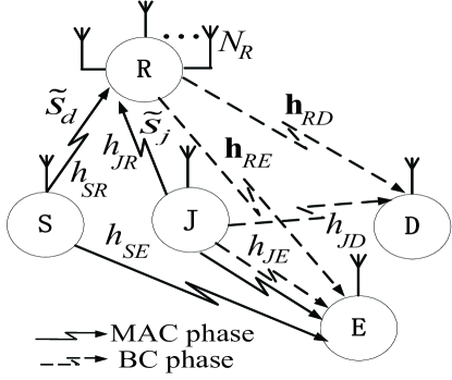
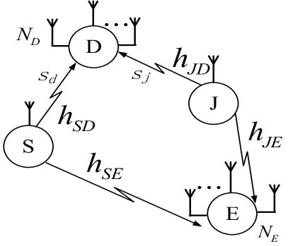
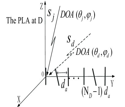
As shown in Fig. 3, source , destination , eavesdropper and jammer are all equipped with single-antenna, while relay employs the -antenna PSA. Owing to the limit coverage of , there exists no direct communication link between and . Therefore, transmits confidential signal to via . Specifically, in the first phase known as multiple access (MAC) phase, transmits to , and then in the second phase called broadcast (BC) phase, forwards the received signal in the first phase to . Again, owing to the existence of eavesdropper , jammer is introduced to transmit jamming signal to decrease the information leakage which happens between and as well as between and . The transmissions of source and jammer in the MAC phase are synchronized, while the transmissions of relay and jammer in the BC phase are also synchronized. For this relay network, it is reasonable to assume that source transmits signal using maximum transmit power.
| (61) | ||||
| (62) |
IV-A Secrecy Rate Maximization with Perfect CSI
Similar to Section III, the scalar denotes the flat-fading and quasi-static channel from node to node where and , while and denote the channel gains from source and jammer to the reference antenna of the relay’s PSA, respectively. Furthermore, the CSI of eavesdropper is assumed to be available. Based on these assumptions, the received signals at the antennas of relay in the MAC phase can be expressed as
| (51) |
where and are the transmit signals of source and jammer , respectively, with , and are the transmit powers of source and jammer , respectively, while is the Gaussian noise vector at relay whose elements follow the distribution . The spatio-polarized manifold matrices for are defined similarly to (35), and the relay’s PSA spatial pointing vector is defined similarly to (34). The wiretapped signal at in this phase is given by
| (52) |
where the additive Gaussian noise follows the distribution , and .
In the BC phase, relay utilizes the amplify-and-forward (AF) strategy to forward the received signal . To be specific, the retransmitted signal is , where denotes the AF beamforming matrix. Thus, the transmit power of is given by
| (53) |
Simultaneously, jammer sends the interference signal with power to . Let and be the channel gain vectors from the antennas of relay to destination and eavesdropper , respectively, while denotes the channel gain from to . Then the received signals at and are formulated respectively as
| (54) | ||||
| (55) |
Due to the fact that relay adopts the PSA as the transmit array, its antenna correlation matrix must be considered, whose elements follow the exponential model of for with constant [31]. The additive Gaussian noises at destination and eavesdropper are and , respectively, while the equivalent noise-plus-interference terms and are given by
| (56) | ||||
| (57) |
Clearly, the total amount of information leakage to comes from both and , as indicated in (IV-A) and (55). Hence, the wiretapped information in the relay network is given by
| (62) | ||||
| (63) |
The covariance matrix of and are given by (61) and (62), respectively, at the top of the next page, in which . Correspondingly, the achievable secrecy rate region of this relaying network is
| (61) |
in which the mutual information between source and destination and the mutual information between source and eavesdropper are given respectively by
| (62) | |||
| (63) |
The optimization problem for the proposed secure beamforming design is formulated as
| (64) |
where the definition of is similar to that of given in Section III-A, while and are the maximum relay and jammer transmit powers, respectively. It can be observed that the objective function of this problem is a product of two correlated generalized Rayleigh quotients and is obviously nonconvex. Thus this optimization is difficult to solve directly. Since eavesdropper is a legitimate although not an intended receiver, we assume that the perfect CSI of is available. Then the following operations are performed.
1) As the perfect CSI of is available, the beamforming matrix is designed to satisfy . Thus the information leakage from to is canceled completely. With this beamforming matrix design, jammer does not need to transmit signal to decrease the information leakage caused by , which means that .
2) As destination is disturbed by the forwarded jammer signal from the MAC phase, the beamforming matrix should be designed to satisfy to eliminate the interference to caused by jammer completely.
3) Since only jammer signal is utilized to decrease the information leakage to in the MAC phase and , we can set to interfere eavesdropper maximally. Thus the power allocation for jammer is determined.
| (78) | |||
| (79) |
| (86) |
With the operations 1) to 3), the information leakage only occurs in the MAC phase, and the mutual information and are simplified as
| (65) |
| (66) |
Thus the secrecy rate maximization problem (64) can be re-expressed as
| (67) |
Unfortunately, this problem is still neither convex nor concave with respect to and . Similar to solving (24), we propose an iterative suboptimal algorithm to solve (67) effectively.
IV-A1 Optimization of
When the PSA spatial pointing vector is fixed to where is the outer iteration index and for , the problem (67) is transformed into
| (68) |
After some manipulations, (IV-A1) can be rewritten as
| (69) |
where
| (70) | |||
| (71) | |||
| (72) | |||
| (73) | |||
| (74) | |||
| (75) |
Let be the projection matrix onto the null space of . Then the -dimensional relay beamforming vector is denoted as , which transforms the original optimization variable into . Thus, the problem (69) can be rewritten as
| (76) |
The problem in (76) is also a generalized Rayleigh quotient problem, which has the closed-form solution
| (77) |
with and given by (78) and (79), respectively, at the top of this page. Once the optimal is obtained, the optimal can be derived based on .
| (92) |
| (96) |
| (92) | |||
| (93) |
IV-A2 Optimization of
Given , the optimization problem (67) is rewritten as
| (85) |
To simplify this complicated nonconvex problem, we define
| (88) |
Then the feasible must be in the null-space of . Therefore, , where denotes the projection matrix onto the null space of and is the equivalent variable vector to be optimized. By defining the Hermitian matrix , the problem (85) is rewritten as
| (94) |
where
| (95) | ||||
| (96) | ||||
| (97) |
It is observed that the problem (94) becomes a standard SDP problem if the rank-1 constraint is not considered. Similar to solving (30), we utilize the penalty based method to solve (94). The corresponding iterative optimization problem (86) is given at the bottom of this page, where the superscript [t] denotes the inner iteration index, and is the eigenvector corresponding to the maximum eigenvalue . Note that the initial and the upper bound are derived from the problem (94) without considering the rank-1 constraint. Furthermore, the penalty based method and the bisection method are jointly applied to iteratively solve (86) to obtain the optimal rank-1 satisfied . This procedure is terminated when . With the optimal solution , the optimal can be obtained by the eigenvalue decomposition on . Since the iterative optimization (86) has exactly the same form as the iterative optimization (31), the convergence of the iterative algorithm for solving (86) is guaranteed.
Thus, instead of jointly optimizing and , we optimize and separately in an iterative procedure involving steps 1) and 2). Specifically, with the initial iteration index and a feasible initial , we obtain the optimal beamforming matrix using the closed-form solution (77). Then with , the optimal PSA pointing vector is determined by solving (86) iteratively. Because the pair is feasible in next iteration to obtain , the objective function in the original problem (67) is monotonously increasing and it converges to the maximum value as the iteration index increases. Hence, when a preset termination criterion is met, the procedure yields the optimal beamforming matrix and the optimal PSA pointing .
The complexity of this proposed algorithm mainly comes from the iterative SDP optimization (86) for deriving the PSA spatial pointing vector. According to [32], the computational complexity of a standard SDP problem is on the order of
| (87) |
where is the number of semidefinite cone constraints and is the dimension of the semidefinite cone, while is the accuracy imposed to solve the SDP problem. Thus the per-iteration complexity of our proposed algorithm is
| (88) |
IV-B Robust Design for Maximizing Secrecy Rate
In the previous subsection, we obtain the optimal PSA pointing . In most practical deployments, however, the actual array spatial pointing implemented will deviate from this ideal one, due to the antenna distortion, operational environment factors or installation errors. Therefore, it is necessary to design a robust beamforming under an imperfect PSA pointing realization . There exist two types of array pointing errors. One is modeled as a deterministic matrix with bounded norm, and the other is unbounded and denoted by a statistical model of unknown parameters. For simplicity, we only consider the design of robust relay beamforming for the bounded PSA pointing error type. Specifically, an ellipsoid model is utilized to model the PSA spatial pointing error as
| (89) |
where is the optimal PSA pointing for the relaying network obtained in Subsection IV-A, is the elliptical array pointing error, and the matrix determines the accuracy degree of the PSA pointing, which has the Cholesky decomposition of . If the elements of tend to infinity, the PSA pointing error approaches zero, i.e., the actual array structure is perfect. On the other hand, if the elements of approach 0, the PSA pointing is extremely inaccurate.
By considering the array pointing error, the resulting robust secrecy rate maximization problem (92) is formulated at the top of this page. This optimization is highly complicated, and we make some operational assumptions in order to simplify it. First, the robust beamforming matrix is designed to satisfy to cancel the information leakage from to completely. Second, and are also applied to the robust beamforming optimization with the same reasons as given in Subsection IV-A. Under these conditions, (92) can be reformulated as the optimization problem (96) given at the top of this page, where and the lower bound of is zero, while the upper bound of is calculated based on the optimal and from the perfect CSI case. The first two constraints in the optimization problem (96) can be expressed as (92) and (93), respectively, given at the top of this page, where To promote the standard SDP formulation for the robust secrecy beamforming design, we employ the S-procedure lemma [33] to transform (92) and (93) into the linear matrix inequalities and, consequently, the optimization problem (96) is reformulated as
| (102) |
where
| (103) | |||
The optimization (102) is still nonconvex with respect to . Similar to solving (85), some mathematical transformations are applied to reformulate (102) into a standard SDP problem with a rank-1 constraint. Specifically, by defining
| (104) |
the problem (102) is transformed into
| (114) |
where
| (115) | |||
with , for and . The penalty based method can also be used to solve the problem (114) effectively, and the obtained guarantees to satisfy the rank-1 property. The detailed optimization procedure is the same as that presented in Subsection IV-A. This proposed robust beamforming algorithm is based on the iterative SDP optimization, which is similar to the one we used to solve the secrecy rate maximization with perfect CSI presented in Subsection IV-A. Therefore, it has the same order of magnitude of the per-iteration complexity as the algorithm of Subsection IV-A, which can be shown to be
| Scenario | DOA of | Optimized 8-element array spatial angles (degrees) for given |
| SIMO Network | ||
| | ||
| Relaying Network | ||
| |
V Simulation Results
In the simulation study, the DOA of desired signal is specified by , and its POA is given by . For jammer signal , its DOA is with , and its POA is with and . Thus, the spatial and polarization distances between and are given respectively by and [34]. The 8-antenna PSA is considered in our simulations and the antenna spacing is half of the transmit signal wavelength 333Note that our work can also be extended easily to the planar array case with the different spatial phase matrix. Moreover, since the spatial phase matrix is not related to any optimization variable, the simulation conclusions obtained by applying the planar array are similar to that in Section V.. In the SIMO network, the eavesdropper is equipped with antennas. All channel coefficients are generated independently according to and the power of the receive additive noise is . In order to solve the standard convex optimization problems such as the GP (38) and the SDP (86) efficiently, the software toolbox CVX [32] is used. Under this simulation setting, we perform numerical evaluations for the point-to-point SIMO network and the relaying network, respectively. In order to demonstrate the advantages of PSA, the standard CSA based technique is utilized as a comparison. Specifically, instead of employing the 8-element PSA, the destination also employs the CSA with 8 antennas in the SIMO network case, while the relay is also equipped with the 8-element CSA in the relay network case. All the results are averaged over 500 Monte Carlo simulations.
For different DOAs of the jammer signal , Table I presents the optimized spatial pointings of the 8-antenna PSA for both the SIMO network and the relaying network is presented. The corresponding optimal destination beamforming and relay beamforming can be derived from (32) and (77), respectively.
V-A The SIMO Network
We first consider the security performance of the SIMO network with the proposed algorithm for optimizing the receive beamforming, power allocation and PSA spatial pointings.
V-A1 Total power minimization
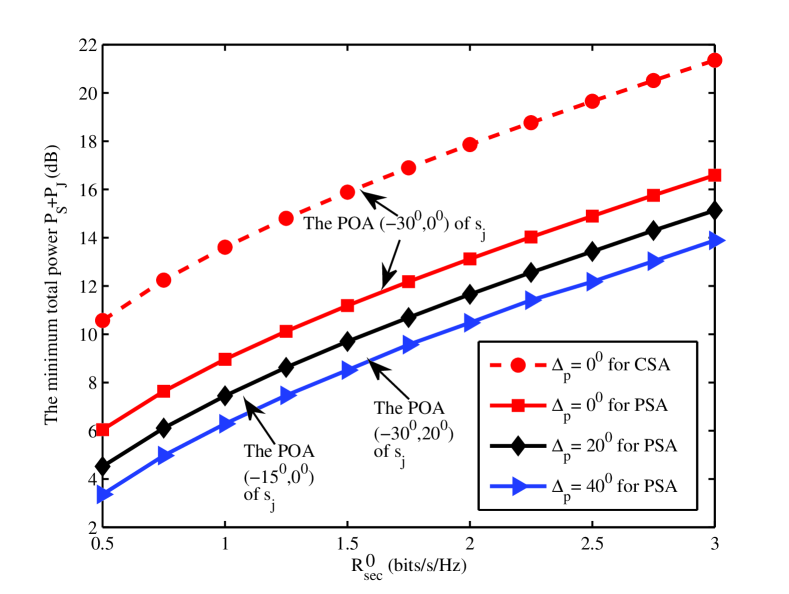
With the -antenna PSA, Fig. 4 depicts the minimum power consumption of the SIMO network as the function of the secrecy rate threshold , under three different polarization distances with the DOA of jammer signal given by , which is slightly difficult from the DOA of desired signal . Thus, the spatial distance between and is only , which is considered to be very small. Three POA values considered for are , corresponding to three polarization distances , and , respectively. It is obvious that the minimum total power consumption is a monotonously increasing function of the required secrecy rate , as clearly indicated in Fig. 4. Also observe from Fig. 4 that for the PSA, increasing leads to reduction in the total power consumption, which confirms that the polarization difference between the two signals is beneficial to improve the power efficiency of the PSA based SIMO network. As a comparison, the minimum total power consumption required by the CSA based SIMO network with the POA of given by is also plotted in Fig. 4, where it can be seen that the CSA needs consume more than 4 dB of power to achieve the required , compared with the PSA. This is because the CSA cannot utilize the signals’ polarization information to improve performance.
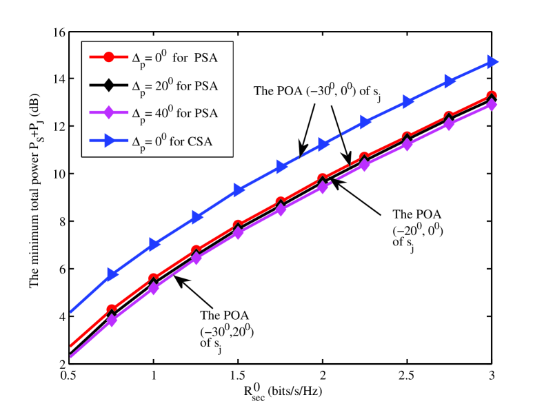
We then change the DOA of to , and repeat the same experiment. The results obtained are shown in Fig. 5. Compared with Fig. 4, we observe that the power consumptions of the both CSA-based and PSA-based SIMO networks are greatly reduced, because we have a large spatial difference between and . From Fig. 5, it can be seen that the three minimum power consumption curves of the PSA for the three different polarization distances become very close. This phenomenon demonstrates that the polarization difference has little effect on the network performance when the two signals have a sufficiently large spatial distance. The results of Fig. 5 again confirm the advantage of the PSA over the CSA, as the former achieves 2 dB saving in power consumption in comparison with the latter.
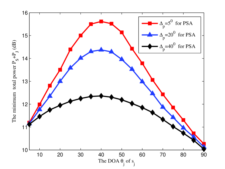
Additionally, Fig. 6 depicts the minimum total power consumption of the PSA SIMO network as the function of DOA of under three different polarization distances and given the secrecy rate threshold bits/s/Hz. It can be seen that as the DOA difference between and , , the power consumption reaches the highest value. Again, increasing the polarization distance leads to the reduction in power consumption, as clearly shown in Fig. 6. Furthermore, when the spatial separation is sufficiently large, the influence of the polarization difference to power consumption becomes very small.
V-A2 Secrecy rate maximization
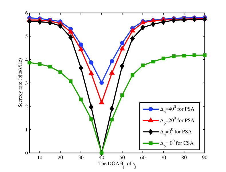
In this investigation, we set the POA of to . The polarization distance between and is given by . Fig. 7 depicts the achievable secrecy rates of the PSA based SIMO network as the functions of the DOA of , given dB. It can be seen that for a given , the achievable secrecy rate is reduced rapidly as the spatial separation between and , , decreases, and when , the achievable secrecy rate reaches the minimum value. It is also clear that the achievable secrecy rate increases with the increase of the polarization separation . Moreover, the influence of to the achievable secrecy rate is particularly strong when the two signals are near spatially inseparable, while the influence of becomes very small when the signals are sufficiently separable in the spatial domain. Note that at and , the secrecy rate is zero. As a comparison, the secrecy rate of the CSA-based SIMO network under is also given in Fig. 7, where it is apparent that the PSA significantly outperforms the CSA.
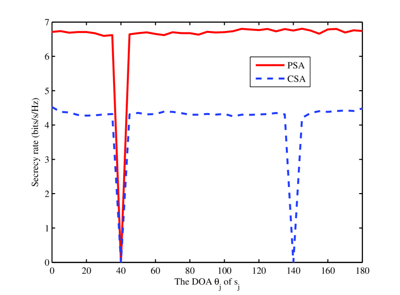
Next we increase to 14 dB and expand the range of from to . Given , Fig. 8 compares the achievable secrecy rate of the PSA SIMO network with that of the CSA SIMO network. As expected, both the PSA and CSA attain a zero secrecy rate at , as at this point, both and . However, it is further noticed that for the CSA, the secrecy rate also deteriorates to zero when the DOA of is . This is owing to the symmetric fuzzification and is referred to as grating lobe. By contrast, the secure communication of the SIMO network employing PSA is realized without introducing grating lobes, which is another significant advantage of the PSA over the CSA.
V-B The Relaying Network
We now investigate the secure communication of the relay aided network. The DOAs and POAs of the incident signals and are the same as those given in Section V-A for the SIMO network. We concentrate on the maximum secrecy rate of the relaying network obtained by the iterative algorithm proposed in Section IV-A, assuming a perfect realization of the PSA pointing vector, but the robust design with imperfect realization of the PSA pointing vector is also studied.
V-B1 The secrecy rate maximization for the relaying network
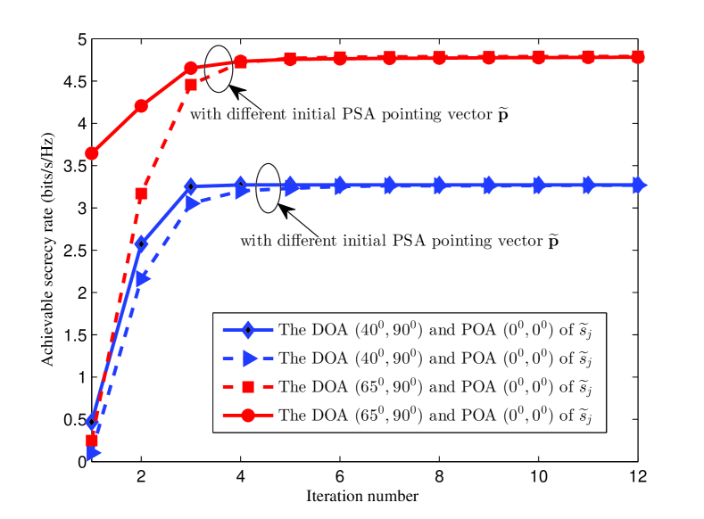
First, we demonstrate the convergence of our proposed iterative optimization algorithm given in Section IV-A. Specifically, we choose the POA for , i.e., we consider the case of , and we set dB, dB and dB. Fig. 9 depicts the convergence performance of the proposed iterative optimization algorithm under both the spatially separable and spatially inseparable cases. It can be seen from Fig. 9 that for the case of , the algorithm takes outer iterations to converge, while for the case of , the algorithm converges within outer iterations. Moreover, the choice of the initial does not seem to affect the algorithm’s convergence performance.
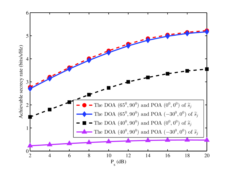
In Fig. 10, the achievable secrecy rate of the PSA relaying network is depicted as the function of the source transmit power , under different DOA and POA of jammer signal with the maximum relay power dB and the maximum jammer power dB. Obviously, the achievable secrecy rate is a monotonically increasing function of but it exhibits a saturation trend for large . This is because increasing also increases the information leakage from source to eavesdropper , while the relay transmit power is limited. Therefore, the achievable secrecy rate cannot go arbitrarily high. With the DOA of given by , which is distinguishable from the DOA of , the influence of the polarization distance between and on the achievable secrecy rate is very small. However, when and are spatially inseparable with , the influence of becomes significant, and a larger leads to a larger achievable secrecy rate. Also observe from Fig. 10 that under the condition of and , the achievable secrecy rate of the PSA relaying network is very small.
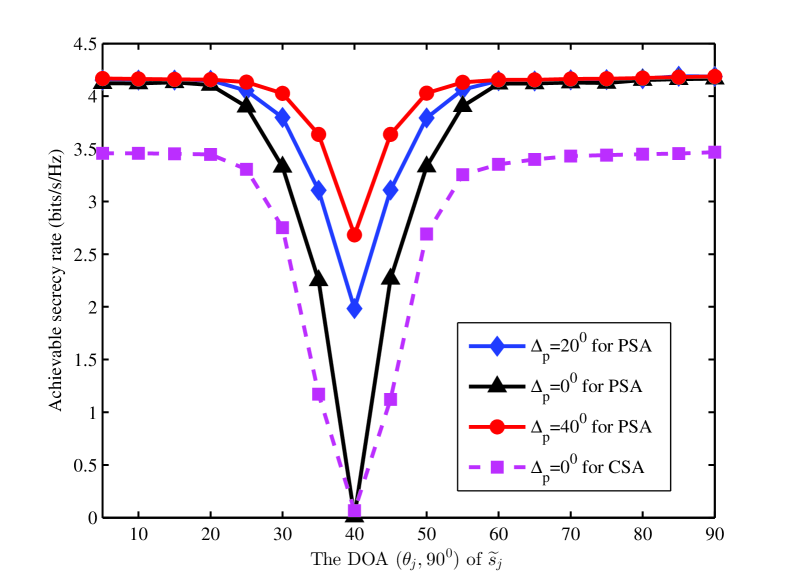
Fig. 11 compares the achievable secrecy rates of the PSA and CSA relaying networks given the DOA for with , dB and dB. In this case, the POA of is given by , and the polarization distance between and is . The results of Fig. 11 demonstrate that the PSA based relaying network significantly outperforms the CSA based relaying network, in terms of achievable secrecy rate. Similar to the SIMO network case, at , the achievable secrecy rates of both the PSA and CSA relaying networks deteriorate to their minimum values. In particular, under the condition of and , the secrecy rate of the CSA relaying network is zero but the secrecy rate of the PSA relaying network is a small nonzero value. Furthermore, by increasing the polarization separation to nonzero, the secrecy rate of the PSA relaying network can be increased considerably, because the PSA can effectively utilize the polarization information.
V-B2 Robust design with imperfect realization of the PSA pointing
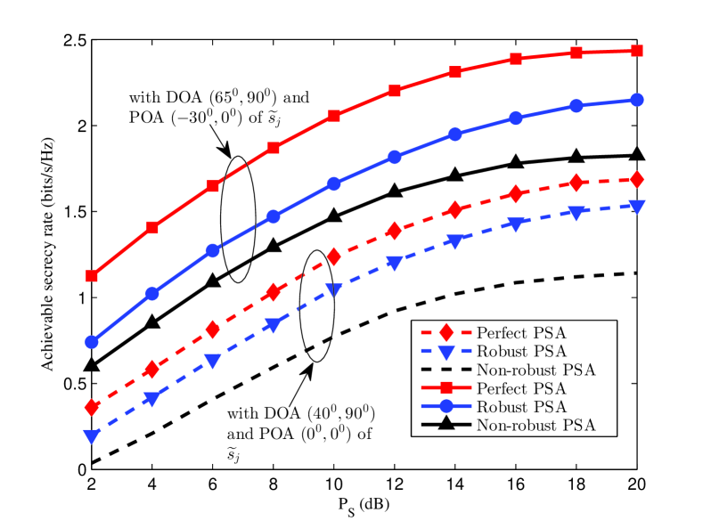
We next illustrate our robust beamforming optimization design for the PSA relaying network with imperfect PSA pointing realization. We set the PSA pointing error bound to . In order to reduce the computation complexity, we consider the -antenna PSA. In Fig. 12, the achievable secrecy rates of three designs as the functions of the maximum source transmit power are depicted, given different DOA and POA conditions for with the 4-antenna PSA as well as dB and dB. Based on the secrecy rate maximization of Section IV-A, we can obtain the optimal design of and . If the PSA pointing implementation is perfect, we can realize the exact optimal PSA pointing solution , which is the curve under the title ‘Perfect PSA’ in Fig. 12. However, in practice, there usually exists PSA pointing implementation error, and the optimal design of is actually implemented as , which is the curve under the title ‘Non-robust PSA’ in Fig. 12. Obviously, this implementation is far from optimal, and the actual secrecy rate achieved is significantly lower than that obtained with the perfect implementation of . Under the imperfect implementation of , our robust beamforming optimization design presented in Section IV-B is capable of re-gaining considerable secrecy rate performance, which is shown in Fig. 12 under the title ‘Robust PSA’.
V-C Extension to the PSA based eavesdropper
As mentioned before, our work can also be easily extended to the case where the PSA is deployed at the eavesdropper. Note that the PSA-based eavesdropper can effectively suppress the interference with approximate spatial properties as the source, and further improve the wiretap capability. In order to illustrate the good performance of the PSA-based eavesdropper, we perform the following two simulations for total power minimization and secrecy rate maximization, respectively.
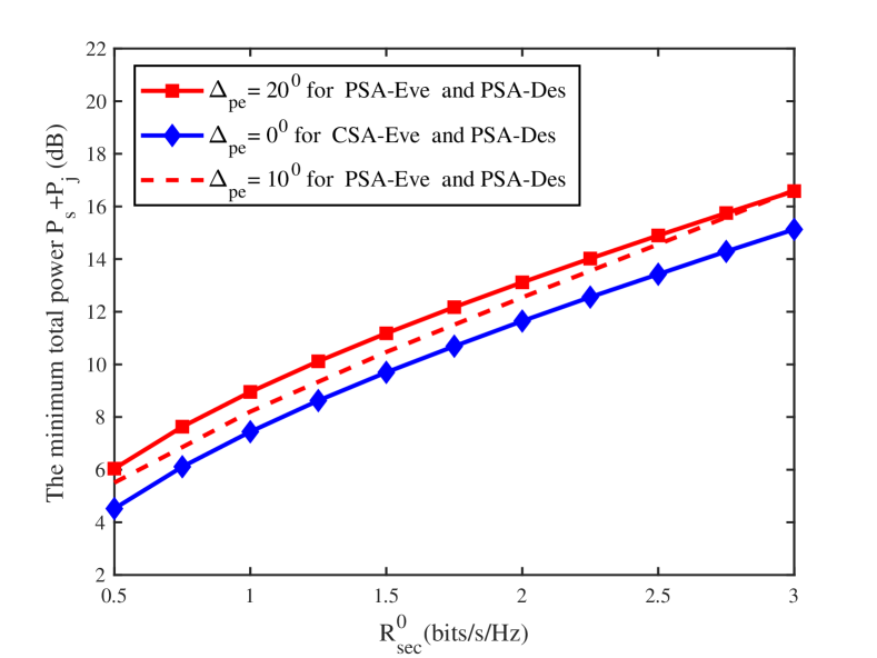
Particularly, we assume that the eavesdropper is equipped with a PSA with antennas. Besides, the DOA and POA of the desired signal impinging on PSA at eavesdropper are assumed to be and , respectively. For jammer signal , its DOA at eavesdropper is and its POA is . Based on this, the polarization distance at eavesdropper between and is defined as , which is similar to that of the polarization distance at destination . Note that in the following two simulations, is fixed. In Fig. 13, the total power consumption of the SIMO network versus the secrecy rate threshold under different polarization distances is studied. Here, both the eavesdropper equipped with the CSA and PSA (also named CSA-Eve and PSA-Eve), are considered. Firstly, we find that for both CSA-Eve and PSA-Eve, the total power consumption increases with . Secondly, it is clear that the total power consumption for PSA-Eve case increases with , which dues to the fact that the wiretap capability of PSA-Eve is enhanced by enlarging the polarization distance . More importantly, compared to the case of CSA-Eve, the total power consumption for PSA-Eve case is evidently higher under the arbitrary polarization distance , which indicates that more transmit power is required to suppress the interception of PSA-Eve and further achieve the secrecy rate threshold.
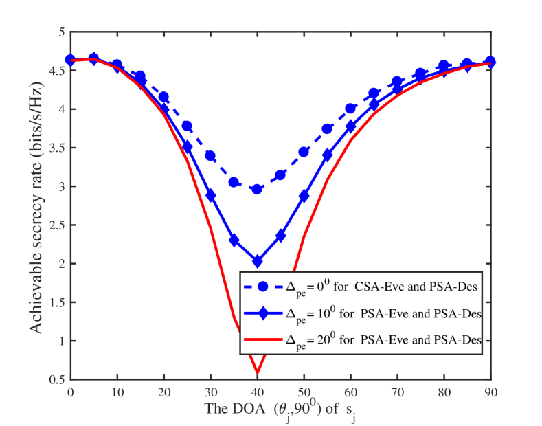
In Fig. 14, the achievable secrecy rate versus the DOA of for both PSA-Eve and CSA-Eve case is shown. The same parameters in Fig. 1 are adopted, and the total transmit power is assumed. Based on this, we naturally find that for both PSA-Eve and CSA-Eve, when the DOA of is near to that of the desired signal, i.e. , the secrecy rate performance evidently deteriorates due to the similar spatial characteristics between the desired signal and the jammer signal. Besides, with the increase of polarization distance , i.e., from to , the PSA-Eve can utilize more polarization difference to improve the wiretap rate and further reduce the achievable secrecy rate. More importantly, compared to the case of CSA-Eve, the lower achievable secrecy rate of PSA-Eve is observed, which is attributed to the better wiretap capability of PSA-Eve.
VI Conclusions
In this paper, a joint beamforming, power allocation and PSA pointing optimization has been proposed for wireless communications. Our main contribution has been to apply the polarization sensitive array to improve the security performance of wireless communications. Specifically, by utilizing the polarization difference among signals, the interference caused by jammer to destination is greatly reduced while the information leakage to eavesdropper is minimized, even when these signals are spatially indistinguishable. Two communication scenarios, the PSA based SIMO network and the PSA aided relaying network, have been considered. For the former scenario, both total transmit power minimization and secrecy rate maximization have been performed. For the relaying network assuming perfect CSI, both secrecy rate maximization designs under perfect and imperfect PSA spatial pointing implementations have been obtained. Since all the optimization problems involved are nonconvex with complicated constraints and/or objectives, alternative suboptimal algorithms have been proposed which enable us to apply convex optimization techniques to solve the transformed optimization problems efficiently. Extensive simulation results have demonstrated the effectiveness of our proposed PSA based techniques for enhancing physical-layer security. In particular, it has been shown that the improvement of maximum achievable secrecy rate of wireless networks by the proposed PSA techniques over the standard CSA techniques is remarkable.
The convergence of the proposed iterative algorithm to solve the optimization problem (31) was demonstrated in [29]. Here we prove the convergence of this algorithm.
Firstly, we define the following objective function
| (116) |
Then the lower bound of is zero according to the following lemma.
Lemma 1
For an arbitrary square matrix , it holds that , in which the equality is guaranteed if and only if is satisfied.
Next, we modify into the following penalty function
| (117) |
where is the objective function in the th iteration of (31).
Let be the optimal matrix obtained at the th iteration of (31). Using in the iterative optimization procedure yields the optimal matrix at the th iteration, which is feasible. Clearly, the optimized satisfies
| (118) |
For an arbitrary Hermitian matrix , the following relationship holds
| (119) |
Therefore, we further obtain
| (120) |
Based on (VI), the function satisfies
| (121) |
where the first inequality and the second inequality hold due to (VI) and (VI), respectively.
Thus, given an initial feasible , the optimization problem (31) can be iteratively solved to obtain a sequence , , whose rank approaches 1. Since this iteration procedure is monotonically decreasing, in terms of the objective function , as shown in (VI), which has a lower bound of zero based on Lemma 1, it is naturally converged. Consequently, we conclude that the iterative optimization problem (31) based on the penalty function method converges to a rank-1 solution.
References
- [1] X. Wang and P. Yi, “Security framework for wireless communications in smart distribution grid,” IEEE Trans. Smart Grid, vol. 2, no. 4, pp. 809–818, Dec. 2011.
- [2] Y. W. P. Hong, P.-C. Lan and C.-C. J. Kuo, “Enhancing physical-layer secrecy in multiantenna wireless systems: an overview of signal processing approaches,” IEEE Signal Process. Mag., vol. 30, no. 5, pp. 29–40, Sep. 2013.
- [3] A. P. Sawlikar, Z. J. Khan, and S. G. Akojwar, “Power optimization of wireless sensor networks using encryption and compression techniques,” in Proc. ICESC 2014 (Nagpur, India), Jan. 9-11, 2014, pp. 222–227.
- [4] W. Trappe, “The challenges facing physical layer security,” IEEE Commun. Mag., vol. 53, no. 6, pp. 16–20, Jun. 2015.
- [5] C. Shannon, “Communication theory of secrecy systems,” Bell System Technical J., vol. 28, no. 4, pp. 656–715, Oct. 1949.
- [6] A. D. Wyner, “The wire-tap channel,” Bell System Technical J., vol. 54, no. 8, pp. 1355–1387, Oct. 1975.
- [7] S. Leung-Yan-Cheong and M. E. Hellman, “The Gaussian wire-tap channel,” IEEE Trans. Inf. Theory, vol. 24, no. 4, pp. 451–456, Jul. 1978.
- [8] Z. Ding, Z. Ma and P. Fan, “Asymptotic studies for the impact of antenna selection on secure two-way relaying communications with artificial noise,” IEEE Trans. Wireless Commun., vol. 13, no. 4, pp. 2189–2203, Apr. 2014.
- [9] F. Zhu, F. Gao, M. Yao, and H. Zou, “Joint information- and jamming-beamforming for physical layer security with full duplex base station,” IEEE Trans. Signal Process., vol. 62, no. 24, pp. 6391–6401, Dec. 2014.
- [10] L. Zhang, Y. Cai, R. C. de Lamare, and M. Zhao, “Robust multi-branch Tomlinson-Harashima source and relay precoding scheme in nonregenerative MIMO relay systems,” in Proc. VTC-2013 Spring (Dresden, Germany), Jun. 2-5, 2013, pp. 1–5.
- [11] W. C. Liao, T. H. Chang, W. K. Ma, and C. Y. Chi, “QoS-based transmit beamforming in the presence of eavesdroppers: an optimized artificial-noise-aided approach,” IEEE Trans. Signal Process., vol. 59, no. 3, pp. 1202–1216, Mar. 2011.
- [12] M. P. Daly and J. T. Bernhard, “Directional modulation technique for phased arrays,” IEEE Trans. Antennas Propag., vol. 57, no. 9, pp. 2633–2640, Sep. 2009.
- [13] A. Kalantari, M. Soltanalian, S. Maleki, S. Chatzinotas, and B. Ottersten, “Directional modulation via symbol-level precoding: a way to enhance security,” IEEE J. Sel. Topics Signal Process., vol. 10, no. 8, pp. 1478–1493, Dec. 2016.
- [14] A. D. Nesic and D. A. Nesic, “Printed planar array antenna with circular polarization for millimeter wave application,” IEEE Antennas Wireless Propagation Lett., vol. 11, pp. 744–747, 2012.
- [15] M. Costa, A. Richter, and V. Koivunen, “Unified array manifold decomposition based on spherical harmonics and 2-D Fourier basis,” IEEE Trans. Signal Process., vol. 58, no. 9, pp. 4634–4645, Sep. 2010.
- [16] W. C. Y. Lee and Y. Yeh, “Polarization diversity system for mobile radio,” IEEE Trans. Commun., vol. 20, no. 5, pp. 912–923, Oct. 1972.
- [17] P. L. Carro and J. de Mingo, “Polarization diversity with genetic parallel printed dipole antennas for Bluetooth and WiMAX applications,” in Proc. VTC-2006 Fall (Montreal, Canada), Sep. 25-28, 2006, pp. 1–5.
- [18] A. J. Weiss and B. Friedlander, “Maximum likelihood signal estimation for polarization sensitive arrays,” IEEE Trans. Antennas Propagat., vol. 41, no. 7, pp. 918–925, Jul. 1993.
- [19] H. Chen, Q. Wan, Y. P. Liu, and A. M. Huang, “A sparse signal reconstruction perspective for direction-of-arrive estimation with a distributed polarization sensitive array,” in Proc. IEEE WCSP 2009 (Nanjing, China), Nov. 13-15, 2009, pp. 1–5.
- [20] S. Nanba, N. Miyazaki, Y. Hirota, and Y. Kishi, “MIMO capacity estimation based on single and dual polarization MIMO channel measurements,” in Proc. 16th Asia Pacific Conf. Commun. (Auckland, New Zealand), Oct. 31-Nov. 3, 2010, pp. 313-318.
- [21] J. Wu and M. C. Wu, “Dual-polarization frequency reuse with frequency band shifting allocation,” IEEE Trans. Veh. Technol., vol. 49, no. 6, pp. 2244–2256, Nov. 2000.
- [22] B. Vrigneau, J. Letessier, P. Rostaing, and L. Collin, “Max-dmin precoder performances in a polarization diversity MIMO channel,” in Proc. 40th Asilomar Conf. Signals Syst. and Comput. (Pacific Grove, CA), Oct. 29-Nov. 1, 2006, pp. 1615-1619.
- [23] A. B. Gershman, N. D. Sidiropoulos, S. Shahbazpanahi, M. Bengtsson, and B. Ottersten, “Convex optimization-based beamforming,” IEEE Signal Process. Mag., vol. 27, no. 3, pp. 62–75, May 2010.
- [24] C. A. Balanis, Antenna Theory: Analysis and Design (3rd Edition). Hoboken, NJ: John Wiley & Sons, 2005.
- [25] V. N. Tatarinov, “The use of the emergence principle as a new step in the electromagnetic waves polarization theory at the scattering by complex random radar objects,” in Proc. MIKON 2006 (Krakow, Poland), May 22-24, 2006, pp. 511–518.
- [26] A. Nehorai, K.-C. Ho, and B. T. G. Tan, “Minimum-noise variance beamformer with an electromagnetic vector sensor,” IEEE Trans. Signal Process., vol. 47, no. 3, pp. 601–618, Mar. 1999.
- [27] G. Barriac, R. Mudumbai, and U. Madhow, “Distributed beamforming for information transfer in sensor networks,” in Proc. IPSN 2004 (Berkeley, CA), Apr. 26-27, 2004, pp. 81–88.
- [28] H. M. Wang, Q. Yin, and X. G. Xia, “Distributed beamforming for physical-layer security of two-way relay networks,” IEEE Trans. Signal Process., vol. 60, no. 7, pp. 3532–3545, Jul. 2012.
- [29] H. M. Wang, M. Luo, Q. Yin, and X. G. Xia, “Hybrid cooperative beamforming and jamming for physical layer security of two-way relay networks,” IEEE Trans. Inf. Forensics Security, vol. 8, no. 12, pp. 2007–2020, Dec. 2013.
- [30] C. Lameiro, J. Via and I. Santamaria, “Amplify-and-forward strategies in the two-Way relay channel with analog Tx-Rx beamforming,” IEEE Trans. Veh. Technol, vol. 62, no. 2, pp. 642-654, Feb. 2013.
- [31] M. Ding and S. D. Blostein,“MIMO minimum total MSE transceiver design with imperfect CSI at both ends,” IEEE Trans. Signal Process., vol. 57, no. 3, pp. 1141–1150, Mar. 2009.
- [32] M. C. Grant and S. P. Boyd, The CVX Users’ Guide (Release 2.1) CVX Research, Inc., 2015.
- [33] C. Shen, T. H. Chang, K. Y. Wang, and Z. Qiu, “Distributed robust multicell coordinated beamforming with imperfect CSI: An ADMM approach,” IEEE Trans. Signal Process., vol. 60, no. 6, pp. 2988-3003, Jun. 2012.
- [34] K. C. Ho, K. C. Tan, and A. Nehorai, “Estimating directions of arrival of completely and incompletely polarized signals with electromagnetic vector sensors,” IEEE Trans. Signal Process., vol. 47, no. 10, pp. 2845–2852, Oct. 1999.