Single microwave-photon detector using an artificial -type three-level system
Abstract
Single photon detection is a requisite technique in quantum-optics experiments in both the optical and the microwave domains. However, the energy of microwave quanta are four to five orders of magnitude less than their optical counterpart, making the efficient detection of single microwave photons extremely challenging. Here, we demonstrate the detection of a single microwave photon propagating through a waveguide. The detector is implemented with an “impedance-matched” artificial system comprising the dressed states of a driven superconducting qubit coupled to a microwave resonator. We attain a single-photon detection efficiency of with a reset time of ns. This detector can be exploited for various applications in quantum sensing, quantum communication and quantum information processing.
pacs:
Single-photon detection is essential to many quantum-optics experiments, enabling photon counting and its statistical and correlational analyses Hadfield (2009). It is also an indispensable tool in many protocols for quantum communication and quantum information processing Gisin et al. (2002); Knill et al. (2001); O’Brien (2007); Aaronson (2011). In the optical domain, various kinds of single-photon detectors are commercially available and commonly used Hadfield (2009); Eisaman et al. (2011). However, despite the latest developments in nearly-quantum-limited amplification Bergeal et al. (2010); Macklin et al. (2015) and homodyne measurement for extracting microwave photon statistics Lang et al. (2013), the detection of a single microwave photon in an itinerant mode remains a challenging task due to its correspondingly small energy. Meanwhile, the demand for such detectors is rapidly increasing, driven by applications involving both microwave and hybrid optical-microwave quantum systems.
In this report we demonstrate an efficient and practical single-microwave-photon detector based on the deterministic switching in an artificial -type three-level system implemented using the dressed states of a driven superconducting quantum circuit. The detector operates in a time-gated mode and features a high quantum efficiency , a low dark-count probability , a bandwidth MHz, and a fast reset time ns. It can be readily integrated with other components for microwave quantum optics.
Our detection scheme carries several advantages compared with previous proposals. It uses coherent quantum dynamics, which minimizes energy dissipation upon detection and allows for rapid resetting with a resonant drive, in contrast to schemes that involve switching from metastable states of a current-biased Josephson junction into the finite voltage state Romero et al. (2009); Peropadre et al. (2011); Chen et al. (2011). Moreover, our detection scheme does not require any temporal shaping of the input photons, nor precise time-dependent control of system parameters adapted to the temporal mode of the input photons, in contrast to recent photon-capturing experiments Yin et al. (2013); Palomaki et al. (2013); Wenner et al. (2014). It also achieves a high efficiency without cascading many devices Romero et al. (2009); Sathyamoorthy et al. (2014).
The operating principle of the detector fully employs the elegance of waveguide quantum electrodynamics, which has recently attracted significant attention in various contexts surrounding photonic quantum information processing Duan and Kimble (2004); Chang et al. (2007); Witthaut and Sørensen (2010); Zheng et al. (2013). When electromagnetic waves are confined and propagate in an one-dimensional (1D) mode, their interaction with a quantum emitter/scatterer is substantially simplified and enhanced compared with three-dimensional cases. These advantages result from the natural spatial-mode matching of the emitter/scatterer with a 1D mode and its resulting enhancement of quantum interference effects. Remarkable examples are the perfect extinction of microwave transmission for an artificial atom coupled to a 1D transmission line Astafiev et al. (2010); Hoi et al. (2011), the photon-mediated interaction between two remote atoms coupled to a 1D transmission line van Loo et al. (2013), and the perfect absorption — and thus “impedance matching” — of a -type three-level system terminating a 1D transmission line Koshino et al. (2013); Inomata et al. (2014). In the latter system, the incident photon deterministically induces a Raman transition which switches the state of the system Pinotsi and Imamoglu (2008); Koshino et al. (2013). This effect has recently been demonstrated in both the microwave and optical domains Inomata et al. (2014); Shomroni et al. (2014), indicating its potential for photon detection Koshino et al. (2015a) as well as for implementing deterministic entangling gates with photonic qubits Koshino et al. (2010).
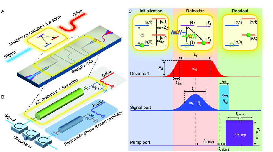
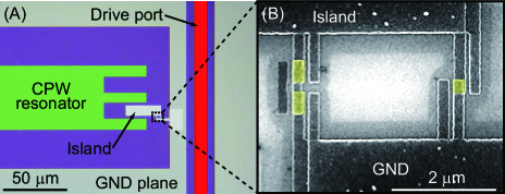
Our device consists of a superconducting flux qubit capacitively and dispersively coupled to a microwave resonator (Fig. 1B) Inomata et al. (2012). With a proper choice of the qubit drive frequency and power , the system functions as an impedance-matched system with identical radiative decay rates from its upper state to its two lower states (Fig. 1A) Koshino et al. (2013); Inomata et al. (2014). The qubit-resonator coupled system is connected to a parametric phase-locked oscillator (PPLO), which enables fast and non-destructive qubit readout Lin et al. (2014).
Figure 1C shows the level structure of the qubit-resonator system and the protocol for the single photon detection. We label the energy levels and their eigenfrequencies , where and respectively denote the qubit state and the photon number in the resonator. In the dispersive coupling regime, the qubit-resonator interaction renormalizes the eigenfrequencies to yield and , where and are the renormalized frequencies of the qubit and the resonator, respectively, and is the dispersive frequency shift of the resonator due to its interaction with the qubit. Only the lowest four levels with or are relevant here.
We prepare the system in its ground state (Fig. 1C, Initialization) and apply a drive pulse to the qubit (Fig. 1C, Detection). In a frame rotating at , the level structure becomes nested, i.e., , for in the range . On the plateau of the drive pulse (), the lower-two levels and (higher-two levels and ) hybridize to form dressed states and ( and ). Under a proper choice of , the two radiative decay rates from (or ) to the lowest-two levels become identical. Thus, an impedance-matched system comprising , , and (alternatively, , , and ) is realized. An incident single microwave photon (Gaussian envelope, length ), synchronously applied with the drive pulse through the signal port and in resonance with the transition, deterministically induces a Raman transition, , and is down-converted to a photon at the transition frequency. This process is necessarily accompanied by an excitation of the qubit Koshino et al. (2013); Inomata et al. (2014).
To detect the photon, we adiabatically switch off the qubit drive and dispersively read out the qubit state (Fig. 1C, Readout). We apply a readout pulse with the frequency through the signal port, which, upon reflection at the resonator, acquires a qubit-state-dependent phase shift of or . This phase shift is detected by the PPLO with high fidelity: in the present setup, the readout fidelity of the qubit is , which is primarily limited by qubit relaxation prior to readoutLin et al. (2014).
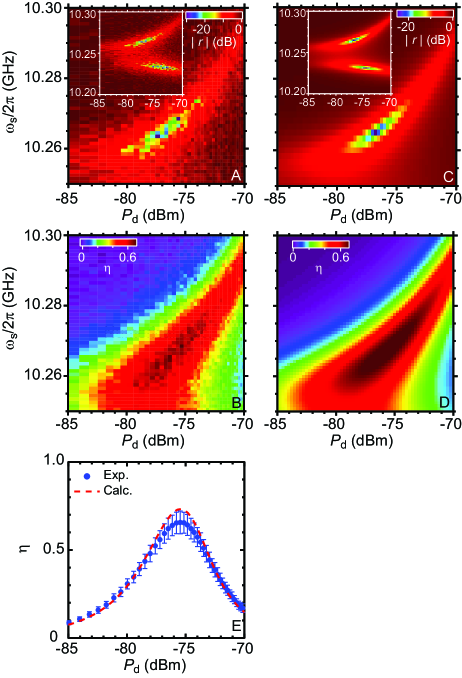
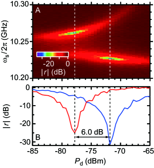
We first determine the operating point where the system deterministically absorbs a signal photon. We simultaneously apply a drive pulse of length ns and a signal pulse of length ns, and proceed to measure the reflection coefficient of the signal pulse as a function of the drive power and the signal frequency (Fig. 2A). The signal pulse is in a weak coherent state with mean photon number . A pronounced dip with a depth of dB is observed in at , in close agreement with theory (Fig. 2C). The dip indicates a near-perfect absorption condition, i.e., impedance matching, where the reflection of the input microwave photon vanishes due to destructive self-interference. Correspondingly, a deterministic Raman transition of is induced, and the qubit state is flipped.
To obtain a ‘click’ corresponding to single-photon detection, we read out the qubit state by using the PPLO immediately after the Raman transition. Before initiating readout, the drive pulse is turned off to suppress unwanted Raman transitions induced by the readout pulse, e.g., . We repeatedly apply the pulse sequence in Fig. 1C times and evaluate the single-photon detection efficiency , where and are the probabilities for the qubit being in the excited state and the signal pulse being in the vacuum state, respectively. Figure 2B depicts as a function of and . The dark count probability of the detector — mainly caused by the nonadiabatic qubit excitation due to the drive pulse and the imperfect initialization — is subtracted when evaluating Sup . We observe that is maximized at the dip position in Fig. 2A in accordance with the impedance-matching condition. We also confirm that the result agrees with numerical calculations based on the parameters determined independently (Fig. 2D). The maximum value, , is obtained at (Fig. 2E) Sup . The efficiency exceeds 0.5 over a signal-frequency range of MHz, which is comparable to the bandwidth of the detector, MHz Sup .
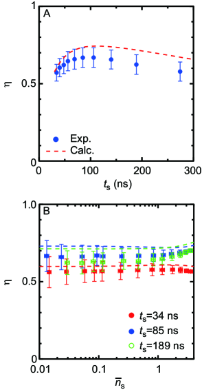
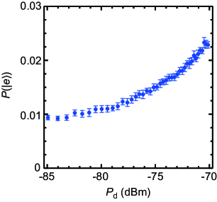
In the Fig. 3A, we plot efficiency as a function of the signal pulse length . Here, we fix and at the values which maximize in Fig. 2E. The drive pulse duration is set to be ns, which empirically maximizes at each . We observe that is a non-monotonic function of and attains a maximum at ns. The initial increase of at short is due to the narrowing of the signal bandwidth resulting in an improved overlap with the detection bandwidth. For longer , the qubit relaxation limits Koshino et al. (2015a). Next, we examine how the photon detector behaves when in the signal pulse is varied. Figure 3B shows as a function of for fixed signal pulse lengths at , , and ns. The detection efficiencies stay constant for regardless of the pulse lengths. This validates the determination of in our measurements using signal pulses in the weak coherent states. For , slightly depends on because of the possibility to drive multiple Raman transitions.
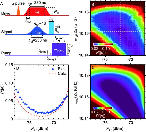
After a single-photon detection event, the qubit remains in the excited state until it spontaneously relaxes to the ground state, which leads to a relatively long dead time of the detector. However, our coherent approach allows us to implement a fast reset protocol (Fig. 4A): in conjunction with the drive pulse that forms the system, we apply a relatively strong reset pulse through the signal port which induces an inverse Raman transition, . We optimize the drive-pulse power and the reset-pulse frequency such that the resulting qubit excitation probability is minimized (Fig. 4B). At the optimal reset point , attains a minimum value , equivalent to the value obtained in the absence of the initial -pulse used to mimic a photon absorption event. Without a reset pulse, we obtain . A comparison of the two results indicates that the reset pulse is highly efficient. Moreover, we confirm that the reset protocol does not affect the succeeding detection efficiency and that the time-gated operation can be repeated in a rate exceeding 1 MHz Sup .
For the moment, the detection efficiency of this detector is limited by the relatively short qubit relaxation time, s.
Nonetheless, our theoretical work indicates that efficiencies reaching are readily achievable with only a modest improvement of the qubit lifetime Koshino et al. (2015a).
An extension from the time-gated-mode to the continuous-mode operation is also possible Koshino et al. (2015b).
This work was partially supported by JSPS KAKENHI (Grant Number 25400417, 26220601, 15K17731), ImPACT Program of Council for Science, and the NICT Commissioned Research.
References
- Hadfield (2009) R. H. Hadfield, Nature Photon. 3, 696 (2009).
- Gisin et al. (2002) N. Gisin, G. Ribordy, W. Tittel, and H. Zbinden, Rev. Mod. Phys. 74, 145 (2002).
- Knill et al. (2001) E. Knill, R. Laflamme, and G. J. Milburn, Nature (London) 409, 46 (2001).
- O’Brien (2007) J. L. O’Brien, Science 318, 1567 (2007).
- Aaronson (2011) S. Aaronson, Proc. R. Soc. A 467, 3393 (2011).
- Eisaman et al. (2011) M. D. Eisaman, J. Fan, A. Migdall, and S. V. Polyakov, Rev. Sci. Instrum. 82, 071101 (2011).
- Bergeal et al. (2010) N. Bergeal, R. Vijay, V. E. Manucharyan, I. Siddiqi, R. J. Schoelkopf, S. M. Girvin, and M. H. Devoret, Nat. Phys. 6, 296 (2010).
- Macklin et al. (2015) C. Macklin, K. O’Brien, D. Hover, M. E. Schwartz, V. Bolkhovsky, X. Zhang, W. D. Oliver, and I. Siddiqi, Science 350, 307 (2015).
- Lang et al. (2013) C. Lang, C. Eichler, L. Steffen, J. M. Fink, M. J. Woolley, A. Blais, and A. Wallraff, Nat. Phys. 9, 345 (2013).
- Romero et al. (2009) G. Romero, J. J. Garca-Ripoll, and E. Solano, Phys. Rev. Lett. 102, 173602 (2009).
- Peropadre et al. (2011) B. Peropadre, G. Romero, G. Johansson, C. M. Wilson, E. Solano, and J. J. García-Ripoll, Phys. Rev. A 84, 063834 (2011).
- Chen et al. (2011) Y.-F. Chen, D. Hover, S. Sendelbach, L. Maurer, S. T. Merkel, E. J. Pritchett, F. K. Wilhelm, and R. McDermott, Phys. Rev. Lett. 107, 217401 (2011).
- Yin et al. (2013) Y. Yin, Y. Chen, D. Sank, P. J. J. O’Malley, T. C. White, R. Barends, J. Kelly, E. Lucero, M. Mariantoni, A. Megrant, C. Neill, A. Vainsencher, J. Wenner, A. N. Korotkov, A. N. Cleland, and J. M. Martinis, Phys. Rev. Lett. 110, 107001 (2013).
- Palomaki et al. (2013) T. A. Palomaki, J. W. Harlow, J. D. Teufel, R. W. Simmonds, and K. W. Lehnert, Nature (London) 495, 210 (2013).
- Wenner et al. (2014) J. Wenner, Y. Yin, Y. Chen, R. Barends, B. Chiaro, E. J. J. Kelly, A. Megrant, J. Y. Mutus, C. Neill, P. J. J. O’Malley, P. Roushan, D. Sank, A. Vainsencher, T. C. White, A. N. Korotkov, A. N. Cleland, and J. M. Martinis, Phys. Rev. Lett. 112, 210501 (2014).
- Sathyamoorthy et al. (2014) S. R. Sathyamoorthy, L. Tornberg, A. F. Kockum, B. Q. Baragiola, J. Combes, C. M. Wilson, T. M. Stace, and G. Johansson, Phys. Rev. Lett. 112, 093601 (2014).
- Duan and Kimble (2004) L.-M. Duan and H. J. Kimble, Phys. Rev. Lett. 92, 127902 (2004).
- Chang et al. (2007) D. E. Chang, A. S. Sørensen, E. A. Demler, and M. D. Lukin, Nat. Phys. 3, 807 (2007).
- Witthaut and Sørensen (2010) D. Witthaut and A. S. Sørensen, New J. Phys. 12, 043052 (2010).
- Zheng et al. (2013) H. Zheng, D. J. Gauthier, and H. U. Baranger, Phys. Rev. Lett. 111, 090502 (2013).
- Astafiev et al. (2010) O. Astafiev, A. M. Zagoskin, A. A. Abdumalikov, Jr., Y. A. Pashkin, T. Yamamoto, K. Inomata, Y. Nakamura, and J. S. Tsai, Science 327, 840 (2010).
- Hoi et al. (2011) I.-C. Hoi, C. M. Wilson, G. Johansson, T. Palomaki, B. Peropadre, and P. Delsing, Phys. Rev. Lett. 107, 073601 (2011).
- van Loo et al. (2013) A. F. van Loo, A. Fedorov, K. Lalumire, B. C. Sanders, A. Blais, and A. Wallraff, Science 342, 1494 (2013).
- Koshino et al. (2013) K. Koshino, K. Inomata, T. Yamamoto, and Y. Nakamura, Phys. Rev. Lett. 111, 153601 (2013).
- Inomata et al. (2014) K. Inomata, K. Koshino, Z. R. Lin, W. D. Oliver, J. S. Tsai, Y. Nakamura, and T. Yamamoto, Phys. Rev. Lett. 113, 063604 (2014).
- Pinotsi and Imamoglu (2008) D. Pinotsi and A. Imamoglu, Phys. Rev. Lett. 100, 093603 (2008).
- Shomroni et al. (2014) I. Shomroni, S. Rosenblum, Y. Lovsky, O. Bechler, G. Guendelman, and B. Dayan, Science 345, 903 (2014).
- Koshino et al. (2015a) K. Koshino, K. Inomata, Z. Lin, Y. Nakamura, and T. Yamamoto, Phys. Rev. A 91, 043805 (2015a).
- Koshino et al. (2010) K. Koshino, S. Ishizaka, and Y. Nakamura, Phys. Rev. A 82, 010301(R) (2010).
- Inomata et al. (2012) K. Inomata, T. Yamamoto, P.-M. Billangeon, Y. Nakamura, and J. S. Tsai, Phys. Rev. B 86, 140508(R) (2012).
- Lin et al. (2014) Z. R. Lin, K. Inomata, W. D. Oliver, K. Koshino, Y. Nakamura, J. S. Tsai, and T. Yamamoto, Nat. Commun. 5, 4480 (2014).
- (32) See Supplemental Material for details on the materials and methods, which includes Refs. [34, 35].
- Koshino et al. (2015b) K. Koshino, Z. Lin, K. Inomata, T. Yamamoto, and Y. Nakamura, arXiv:1509.05858 (2015b).
- Yamamoto et al. (2008) T. Yamamoto, K. Inomata, M. Watanabe, K. Matsuba, T. Miyazaki, W. D. Oliver, Y. Nakamura, and J. S. Tsai, Appl. Phys. Lett. 93, 042510 (2008).
-
(35)
URL:
http://web.physics.ucsb.edu/martinisgroup
/electronics.shtml.
Appendix A Supplemental material for
“Single microwave-photon detector using an artificial -type three-level system”
A.1 Device
Our device is composed of a superconducting coplanar waveguide (CPW) resonator and a superconducting flux qubit (Fig. 1A). The CPW resonator is made of a 50-nm-thick Nb film sputtered on a 300-m-thick undoped silicon wafer with a 300-nm-thick thermal oxide on the surface. It is patterned by electron-beam (EB) lithography using the ZEP520A-7 resist and reactive ion etching. The flux qubit with three Josephson junctions, where one is made smaller than the other two by a factor of , is fabricated by EB lithography and double-angle evaporation of Al using PMMA ( nm)/Ge ( nm)/MMA ( nm) trilayer resist (Fig. 5B). The thicknesses of the bottom and the top Al layers separated by an layer are 20 and 30 nm, respectively. In order to realize a superconducting contact between Nb and Al, the surface of Nb is cleaned by Ar ion milling before the evaporation of Al. The qubit is located at one end of the resonator and is coupled to the resonator dispersively through a capacitance of 4 fF, while it is coupled to the drive port inductively (Fig. 5A).
The flux qubit is always biased with a half flux quantum where the transition frequency of the qubit from the ground state to the excited state is GHz ( ns during photon-detection experiments), while the resonator frequency is GHz ( factor ) when the qubit is in the state. It is shifted by a dispersive interaction with the qubit of MHz, which is enhanced by the straddling effect and the capacitive coupling Inomata et al. (2012) when the qubit is in the state. Note that and denote not their bare frequencies but the renormalized ones including the dispersive shifts Inomata et al. (2014).
A parametric phase-locked oscillator (PPLO) Lin et al. (2014), which is previously operated as a flux-driven Josephson parametric amplifier (JPA) Yamamoto et al. (2008) consists of a superconducting CPW resonator terminated by a dc-SQUID (superconducting quantum interference device). A pump port is coupled to the SQUID loop inductively. The device was fabricated by the planarized Nb trilayer process at MIT Lincoln Laboratory. The resonator and the pump port are made out of a 150-nm-thick Nb film sputtered on a Si substrate covered by a 500-nm-thick SiO2 layer. A static resonant frequency of the PPLO is GHz. The PPLO chip is the same as the one used in Ref. Lin et al. (2014).
A.2 Experimental setup
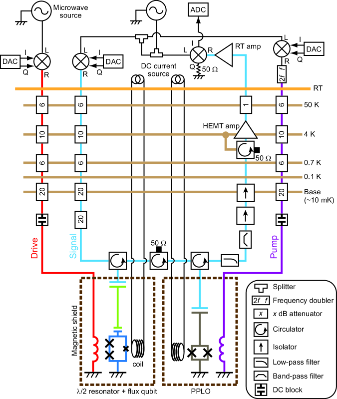
A schematic of the measurement setup including the wiring in a cryogen-free 3He/4He dilution refrigerator, circuit components, and instruments used in the experiment is shown in Fig. 6.
The qubitresonator and the PPLO circuits are fabricated on separate chips and are separately mounted in microwave-tight packages equipped with an independent coil for the flux bias. They are protected independently by the Cryoperm magnetic shield from an external flux noise such as the geomagnetic field.
Microwave pulses for the drive, signal, and pump ports are generated by mixing the continuous microwaves with pulses which have independent IF frequencies generated by DACs (digital to analog converter) developed by Martinis group at UCSB DAC . The pulses are applied through the input microwave semi-rigid cables, each with attenuators of dB in total, and DC-blocks for the drive and pump ports. For the signal port, the microwave pulses are further attenuated by 20 dB, and are input to the resonator through a circulator to separate the input and reflected waves. The reflected waves are routed to PPLO via three circulators (- GHz) and are reflected there again, and are propagated through a low-pass ( GHz) and band-pass filters (- GHz), two isolators (- GHz), and the circulator (- GHz) with a termination. Finally, the signals are amplified by a cryogenic HEMT amplifier and a room-temperature amplifier with a total gain of dB, and mixed with a local oscillator at an I/Q mixer down to the IF frequency. The I component of the reflected signals are sampled at 1 GHz/s by an ADC (analog to digital converter).
For the impedance-matching measurement (Fig. 2A), the PPLO is kept off. Namely, pump pulse is off (the output from the DAC in the pump port is turned off) and is far detuned from so that the PPLO acts as a perfect mirror. In other measurements, the PPLO is kept on.
A.3 Input-power calibration
To estimate the photon detection efficiency precisely, calibration of the signal microwave power level on the sample chip is required. For the calibration, we measure the reflection coefficient as a function of the signal microwave frequency and the drive power and determine the impedance-matching points (Fig. 7). Here, we use continuous microwaves for both the signal and the qubit drive, and set the drive frequency at MHz. We observe two dips representing the impedance matching, similarly to the inset of Fig. 2A. In the limit of weak signal power and no intrinsic loss of the resonator, these dips are expected to appear at the same , where the two radiative decay rates of the system are balanced, and Koshino et al. (2013), where is the radiative decay rate for the transition in the impedance-matched system. In the actual system, however, the finite population in the level as well as the intrinsic loss of the resonator weakens the elastic photon scattering from the system, and the impedance matching occurs when the radiative decay rates are not balanced, and Inomata et al. (2014). This yields a difference in the drive power, , between the two dips. is sensitive to the input signal power: As we increase the signal power, the level is more populated and gets larger. Note that the small observed in the inset of Fig. 2A is attributed to the intrinsic loss of the resonator, since the pulsed signal field is sufficiently weak in this measurement.
We use to calibrate the signal power level. We determine the signal power level which reproduces dB (Fig. 7B) by the numerical simulation, following Ref. Koshino et al. (2013). In the numerical simulation, we employ the following parameters which are estimated by independent measurements: the qubit decay rate MHz (during this measurement shows ns) and the ratio of the external and total decay rates of the resonator photon (for other parameters, see “Device” section of this supplementary material). As a result, the signal power is estimated to be dBm at
maximum ( MHz and ) and dBm at minimum ( MHz and ). Therefore, dBm. This agrees well with an independent estimation of dBm by taking into account the total losses in the input port.
A.4 Protocol for single photon detection
In the main text (Fig. 1C), we show the protocol for single photon detection. Here, we present the detailed parameters of the pulses in the protocol.
The drive frequency is set at , where MHz () is the detuning from the qubit energy, and is fixed through all the experiments described in the main text. The drive pulse is synchronized with the signal pulse with a Gaussian envelope with a length corresponding to its full width at half maximum (FWHM) in the voltage amplitude. The duration of the drive pulse is optimized as ns so that the signal pulse is completely covered by the drive pulse and is efficiently absorbed by the system. In order to suppress unwanted nonadiabatic qubit excitations, the rising and falling edges of the drive-pulse envelope are smoothed by Gaussian function with FWHM of ns in the voltage amplitude.
The readout pulse (the frequency GHz, the length ns, and the mean photon number ) is applied after the delay of from the center of the drive and signal pulses. The reflected readout pulse works as a locking signal for the PPLO output phase, and the pump pulse (the frequency , the length ns, and the power dBm) is applied after ns. The parametric oscillation signal with either or phase is output from the PPLO during the application of the pump pulse, and the data acquisition time of ns is required to extract the phase.
A.5 Photon detection efficiency
In Figs. 2B, 2E, and 3A, a mean photon number in a signal pulse is kept to be , which implies that of the weak-coherent signal pulses contain multiple photons. Our detector responds to the multi-photon pulses but cannot discriminate them from single-photon pulses. The efficiency includes those counts.
A.6 Dark count in the detector
Figure 8 shows the dark count probability in the detector, which is the click probability without applying the signal pulse in the pulse sequence of Fig. 1C. The dark count is mainly caused by the nonadiabatic qubit excitation due to the drive pulse and the imperfect initialization. The probability induced by the latter factor is constant and is measured to be , while the probability induced by the former factor depends on the power and the length of the drive pulse and remains finite even with the Gaussian envelope. We determine the dark count probability before and after each measurement of Figs. 2B, 2E, and Fig. 3 and subtracted the averaged value from the measurement result.
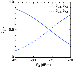
A.7 Time constant of an impedance-matched system
We denote the overall decay rate of the resonator by and the radiative decay rate for the transition in the system by . Figure 9 shows as a function of the drive power , calculated based on the experimental parameters. In the experiment, we choose dBm where the photon detection efficiency reaches the maximum. At this point, . The time constant of the impedance-matched system for the voltage amplitude decay, , is estimated to be ns, where MHz. The shortest signal pulse length is ns in Fig. 3B, which is comparable with .
A.8 Protocol for reset
In the main text (Fig. 4A), we show the reset protocol for the single photon detection. Here, we describe how to optimize the parameters of pulses in the protocol.
We first apply a pulse with the length of ns to directly excite the qubit from the to the state. Then, we apply the drive and reset pulses to induce the transition. To find the operating point to maximize the resetting efficiency, we swept the frequency of the reset pulse and the drive power . After fixing and , we optimize the drive pulse length , and the mean photon number in the reset pulse to minimize . Finally, we measure as a function of and using the reset protocol with optimized parameters. Parameters for the readout and pump pulses are the same as the ones in Fig. 1C.
At the optimal reset point, shows the minimum value of , which results in twice larger occupation of the qubit excited state compared to obtained in the initialization in the equilibrium condition. This indicates the small probability of unwanted nonadiabatic excitations by the drive pulse in the reset protocol.
We demonstrate the microwave photon detection combined with the fast reset protocol. We apply the drive and the signal pulses (the same conditions as in the measurement in Fig. 2B) after the reset protocol and readout the qubit. We accomplish of which is consistent with the maximum obtained in Fig. 2E. This indicates that the photon detection efficiency is unaffected by the reset protocol.
It takes ns to reset the system and ns to detect the single photon for ns. Both of the durations are determined by the drive pulse widths including ns. The qubit readout is completed by accumulating data for ns after ns. The period of the single photon detection including the reset protocol is ns, which allows the photon counting rate of MHz.