Current address: ]Department of Physics, Cornell University, 142 Sciences Dr., Ithaca, New York 14853, USA
Current address: ]Harvard-Smithsonian Center for Astrophysics, 60 Garden Street, Cambridge, Massachusetts 02138, USA.
In-vacuum scattered light reduction with cupric oxide surfaces for sensitive fluorescence detection
Abstract
We demonstrate a simple and easy method for producing low-reflectivity surfaces that are ultra-high vacuum compatible, may be baked to high temperatures, and are easily applied even on complex surface geometries. Black cupric oxide (CuO) surfaces are chemically grown in minutes on any copper surface, allowing for low-cost, rapid prototyping and production. The reflective properties are measured to be comparable to commercially available products for creating optically black surfaces. We describe a vacuum apparatus which uses multiple blackened copper surfaces for sensitive, low-background detection of molecules using laser-induced fluorescence.
I Introdution
Laser-induced fluorescence (LIF) detection is a simple yet powerful technique frequently used in gas-phase atomic and molecular spectroscopy Kinsey (1977); Scoles (1988); Pauly (2000); Demtröder (2015). In many interesting situations, LIF signals are fairly small. For example, in the gas phase, rovibrational branching from molecular electronic states may lead to LIF signals of 1 photon per molecule. Modern experiments with atoms Gross and Bloch (2015), molecules Moerner and Fromm (2003), and ions Leibfried et al. (2003) frequently aim to detect small numbers of particles—sometimes as few as one. In such cases, scattered laser light (and the noise from it) can seriously degrade the signal-to-background and signal-to-noise ratios in LIF detection.
Blackened surfaces are often used to suppress scattered light in LIF detection experiments Scoles (1988); Hall et al. (1984); Pauly (2000). Recently, we have investigated optically black materials for stray light suppression to facilitate efficient detection of molecules via LIF (for use in experiments on laser slowing Barry et al. (2012), cooling Shuman et al. (2010), and trapping Barry et al. (2014); McCarron et al. (2015); Norrgard et al. (2015) of SrF molecules). Here, we present a method for producing ultra-high vacuum (UHV) compatible low-reflectivity surfaces that is simple to implement and very flexible in its utility. Our method, which we refer to as “copper blackening”, uses a simple chemical treatment to produce black, dendritic cupric oxide (CuO) on the surfaces of any pre-formed copper part. We describe the method and present measurements of the reflectance properties of these prepared surfaces. Measurements on blackened copper surfaces are compared to measurements on well-characterized commercial surfaces.
Blackened copper has a number of attractive properties for stray light suppression solutions. Copper is easily machined or formed, and the surfaces may be grown in minutes on parts of any manufactured geometry. Vacuum components may be made of blackened copper, and undesired reflective surfaces may be covered with blackened copper foils or sheets formed into any desired shape. Blackened copper is suitable in UHV from cryogenic temperatures up to 500 ∘C Kirsch and Ekerdt (2001).
II Blackening Method
Copper has two common oxidization states: the red (cuprous oxide) and the black CuO (cupric oxide). The black CuO is effectively grown on the surface of metallic copper by immersing the metal in a solution composed of 100 g of NaOH and 100 g of NaCl per liter of deionized water Meyer (1944). The final step of the reaction,
| (1) |
grows the black CuO Filipič and Cvelbar (2012). The solution’s temperature is maintained between 95 ∘C and 100 ∘C during the blackening process. Thermal and concentration gradients are minimized by using a magnetic stir bar in the blackening solution. Immersing the beaker holding the blackening solution in a heated outer water bath also reduces thermal gradients. The outer bath is saturated with NaCl to allow its temperature to exceed 100 ∘C without boiling and potentially contaminating the solution.
The material used for all parts described in this paper is oxygen-free high conductivity (OFHC) copper (alloy 101), selected for its desirable UHV properties. As described below, we tested OFHC copper prepared with surfaces both as-finished, and sandblasted to increase the roughness. We have also performed the blackening process on alloy 110 Cu and on brass parts, which might be useful in applications where UHV is not a concern (while we have not measured the reflectance properties of these parts, they appear similarly black by eye to the 101 alloy measured in this work). Most steels and titanium are minimally corroded by the solution Sandvik Materials Technology and may be used to hold or remove parts from the solution, but aluminum rapidly dissolves in NaOH.
Prior to blackening, parts are cleaned in an ultrasonic bath of 1 % Citranox in deionized water for one hour to remove any surface contamination, followed by a rinse in a deionized water bath. Parts are then immediately placed in the blackening solution for 10 minutes (by eye, parts blackened for 10 minutes are not distinguishable from parts blackened for 5 or 15 minutes; under similar conditions, the oxide layer thickness was observed to saturate in 2.5 minutes in Ref. Lebbai et al. (2003)). Parts are then removed from the solution, rinsed in a fresh deionized water bath, and placed in an ultrasonic acetone bath for one hour. After a final fresh deionized water rinse, parts are dried with a gentle stream of dry N2.
CuO is known to grow on surfaces in a microstructure of fine dendrites by a number of wet-chemical Filipič and Cvelbar (2012) and electrochemical methods Shao and Zangari (2009); Hu et al. (2010). These dendrites effectively trap incident light Xia et al. (2014), further reducing reflection. Care must be taken when handling the blackened parts, as the CuO dendrites are easily crushed by the pressure of touching the surface, rinsing with a squirt bottle, or drying with a high pressure of compressed gas. Crushing the dendrites is observed to result in a locally less absorptive surface. However, the dendrites are not observed to flake from the surface when crushed, or when subjected to mechanical or ultrasonic vibration.
In some instances, having a part with only some areas blackened is desirable. While we find the thin CuO layer may be easily removed by mechanical means, such as sanding or machining, it is not always possible to perform such operations without crushing the dendrites in the areas where blackening is desired. We have investigated techniques for masking areas to inhibit CuO growth, and found adhesive polytetrafluoroethylene (PTFE) tape to provide good results (see below). PTFE does not react with the blackening solution, and the acrylic adhesive leaves little visible residue; what does remain is removed in the ultrasonic acetone bath typically used in our cleaning procedure. The blackening solution creeps only a few mm under the edges of the tape during a 10 minute blackening, leaving a reasonably sharp boundary.
III Method for Measuring Reflectance
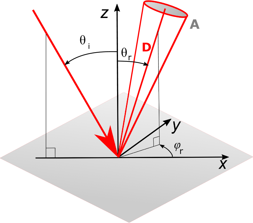
When attempting to eliminate background light, the relative positions of the light source, scattering surface, and detector can significantly affect the relative intensity of scattered light. For example, surfaces typically have dramatically different reflectance properties near normal incidence and near grazing incidence. Because of this, optical reflectance is typically described in terms of the bidirectional reflectance distribution function (BRDF) , defined as
| (2) |
Here, is the power reflected to the detector from incident power . The geometrical quantities used to define are depicted in Fig. 1: is the area of the detector, is the distance from the scattering surface to the detector, and are the incident and reflected polar angles, respectively, and is the relative reflected azimuthal angle.
If the geometric collection efficiency for the scattering source is large (i.e. the detector subtends a large solid angle), or if there are multiple scattering surfaces at different angles relative to the incident light, the directional-hemispherical reflectance (DHR) , defined as
| (3) |
is a more useful characteristic of the surface.
For a simple relative comparison of materials, we direct a laser beam with 1/ diameter 1 mm to intersect the axis of rotation of a turntable, with the sample of interest at its center. The sample and detector photodiode may be rotated independently about this axis. A chopper wheel modulates the incident light power at 3 kHz, and the reflected power is extracted from the detector photodiode signal using a lock-in amplifier. A fraction of the beam is sent to a monitor photodiode to account for source intensity fluctuations. Prior to a reflectance measurement, the signal and monitor photodiodes record and , respectively. During the reflectance measurement, is normalized to the monitor photodiode signal.
The simplicity of this setup limits us to measurements with = 0∘ (forward scattering) or = 180∘ (back scattering). To describe these data, we define the bidirectional azimuth-independent reflection distribution
| Material | 532 nm | 1064 nm | ||
|---|---|---|---|---|
| Bright White 98 | 0.95 | 0.95 | ||
| Blackened Cu, Stock | 0.008 | 0.07 | ||
| Blackened Cu, Sandblasted | 0.008 | 0.06 | ||
| Black Felt | 0.006 | 0.17 | ||
| Acktar Metal Velvet | 0.005 | 0.024 |
| Stock | SandBlasted | |||
|---|---|---|---|---|
| 405 nm | 0.015 | 0.012 | ||
| 532 nm | 0.008 | 0.008 | ||
| 650 nm | 0.010 | 0.013 | ||
| 1064 nm | 0.07 | 0.06 |
function (BAIRDF) as = , with positive (negative) for = ( = ). To assign a value for the DHR from the BAIRDF at normal incidence ( = 0∘), we perform the integral over in Eq. 3 by averaging over the measured values for = and = (This is essentially equivalent to assuming azimuthally symmetric scattering for the case of normal incidence).
IV Discussion of Results
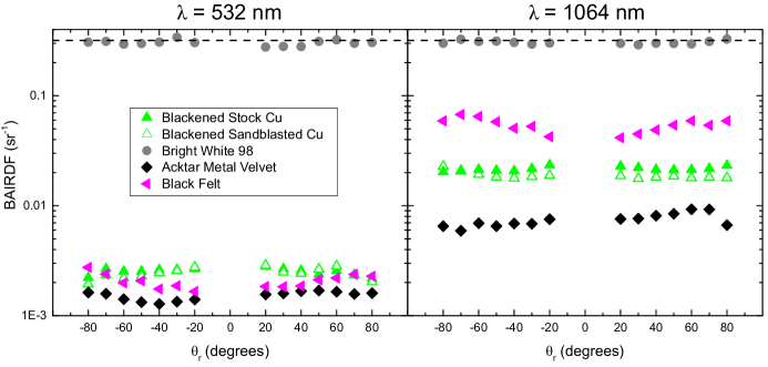
In Fig. 2, we compare at normal incidence for five materials at wavelengths = 532 nm and 1064 nm. Values for = 0 are tabulated in Table 1. To confirm that the calculated and values were reliable, was measured for a near-Lambertian, high-reflectivity surface (Bright White 98). We measured = 0 = 0.95 at 532 nm, compared to the manufacturer-specified value 0.96 typical at 550 nm (no test data at 1064 nm were available from the manufacturer). For a commercial light-absorbing blackened surface provided on aluminum foil (Acktar Metal Velvet, AMV), we measure = 0∘) = 0.005 at 532 nm, also in fair agreement with the manufacturer’s specified typical value of 0.006.
In all cases investigated at normal incidence, the AMV provided the blackest surface. However, the blackened copper had only marginally higher reflectance than the AMV, and proved generally comparable to standard black felt cloth. At normal incidence, no significant difference was measured between blackened copper starting with a stock finish and copper with its surface roughened by sandblasted prior to cleaning and blackening. At = 532 nm, blackened copper is 50% more reflective than black felt, and 75% more reflective than AMV. At 1064 nm, blackened copper is 2 less reflective than black felt, and 3 more reflective than AMV.
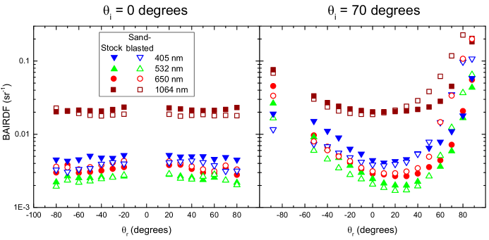
In Fig. 3, we plot the measured BAIRDF as a function of reflected angle for incident angle = 0∘ (left) and = 70∘ (right) for four common laser wavelengths : 405, 532, 650, and 1064 nm. The DHR for normal incidence is given in Table 2. As a consistency check of our BAIRDF data, we note that by reciprocity we expect . For all cases in Fig. 3, these values agree to within 20 %.
At normal incidence, the blackened stock and sandblasted copper display reflectance nearly independent of . Both surface preparation methods produce comparable values of for all wavelengths tested.
Blackened copper produced from stock material was found to specularly reflect for , making it highly ineffective at reducing scattered light at near-grazing incidence. Sandblasting (using sand with typical particle diameter 10 m) produces a diffuse surface over a much larger scale than the typical scale of the dendrites ( 100 nm Xia et al. (2014); Filipič and Cvelbar (2012)). We expected that sandblasting would tend to randomize the surface normal, and indeed no specular reflection component was observed for blackened sandblasted copper for any angle of incidence we were able to test, . However, the removed specular reflection is accompanied by increased forward (positive ) diffuse scatter. For (an incident angle just below the onset of significant specular reflection in blackened stock copper), the stock finish has less forward scatter than the sandblasted copper, while back scatter is lower for the sandblasted copper.
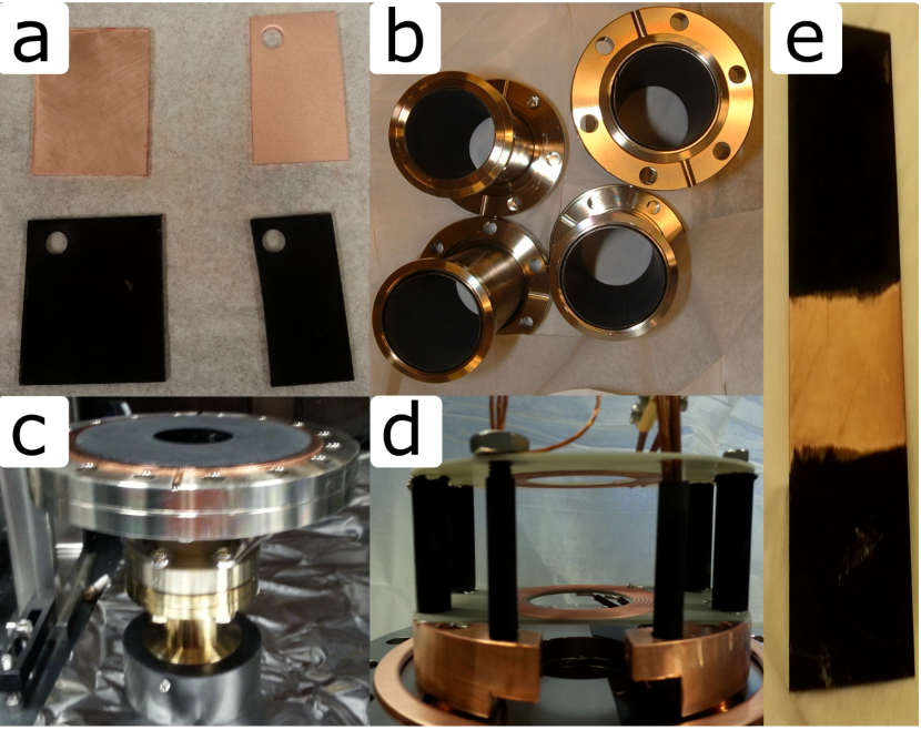
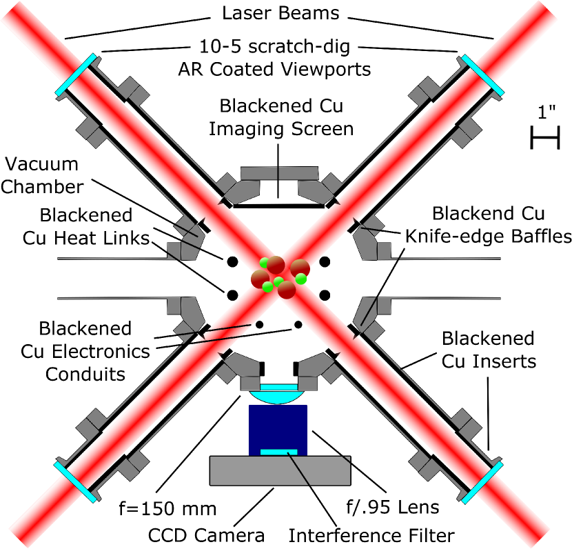
Fig. 4a shows stock and sandblasted copper samples before and after blackening for tests in this work. Copper masked by adhesive PTFE tape is shown in Fig. 4e. Recently, we have used blackened copper surfaces (Fig. 4b-d) to reduce background scattered light in experiments imaging magneto-optically trapped SrF molecules by LIF detection Barry et al. (2014); McCarron et al. (2015); Norrgard et al. (2015). A schematic of the detection region used in Ref. Norrgard et al. (2015) is shown in Fig. 5. A 14 mm 1/ diameter laser beam (the beam is clipped by 23 mm diameter optics external to the vacuum chamber) containing 110 mW of = 663 nm light is passed 6 times through the vacuum chamber (once each along three orthogonal axes and then retroreflected). Excitation by the 660 mW of = 663 nm light in the center of the chamber induces fluorescence from the trapped molecules at the same wavelength. Light is collected by a 2”-diameter, 150-mm-focal-length spherical singlet lens placed directly outside the vacuum chamber, followed by a 50-mm-focal-length, f/0.95 camera lens. The magnification factor at the imaging position is = 0.45. Directly opposite the camera is a blackened Cu screen against which the molecules are imaged. The total light detection efficiency for our system (including geometry, optical losses, and camera quantum efficiency) is 0.4% Barry et al. (2014).
Scattering from the viewports is minimized by using high optical quality (10-5 scratch dig) glass with an anti-reflection V-coating at 663 nm. Standard vacuum nipples with blackened copper sheet inserts (Fig. 4b) reduce stray light in two ways. First, they reduce the power of light scattered directly from viewport surface imperfections into the LIF detection region, simply by placing the viewports further from the imaging chamber ( 10”) than they would be in the absence of the nipple ( 5”). Second, the blackened inserts increase the likelihood that light incident on the walls of the nipple (either directly or through scattering) is absorbed before reaching the imaging region. Background light is additionally reduced by baffles Scoles (1988) formed by blackened Cu rings with a knife-edged inner diameter machined to be 26 mm, which sit inside the imaging chamber flush with the vacuum-sealing Cu gasket.
Fig. 4c shows a blackened copper disk for stray light absorption (not shown in Fig. 5) which covered the entire bottom of the molecule imaging chamber in Barry et al. (2014); McCarron et al. (2015). A hole in the center provides optical access for the two vertical passes of the 663 nm light. For the work in Ref. Norrgard et al. (2015), this disk was replaced with the assembly shown in Fig. 4d, where blackened copper rods serve as heat conduits (thick outer rods) for in-vacuum high-power circuit boards. We found that the unmodified blackened surface does not allow for good thermal contact. However, deliberately crushing the CuO dendrites on the thermally connected surface and applying a 0.004”-thick indium thermal interface layer (TIL) gave nearly the same thermal conductivity as obtained with a typical method for making heat links with unblackened copper (sanding the copper surface with 2000 grit sandpaper and applying an indium TIL). Using an indium TIL without crushing the dendrites gave reduced conductivity (roughly 2 less), similar to that of sanded copper without indium present.
During normal trap operation, we measure the maximum photon scattering rate per molecule to be = 2.5 106 s-1. Analysis is restricted to a region of interest of typically pixels ( mm) where the majority of the LIF signal is imaged. The background scattered light signal is typically e-/pixel/s. For a typical = 60 ms exposure, the noise is usually limited by shot noise in this background, at the level 30 e-/pixel. Under these conditions, the laser intensity noise, camera read noise, and camera dark current are approximately 4, 8 and 104 times smaller than , respectively. Integrating over the region of interest gives a signal-to-noise ratio (SNR) of 0.39 per molecule for a single trap loading shot. With this system, we have observed MOTs of as few as 17 molecules Norrgard et al. (2015), with SNR 110 when averaging over 300 successive shots.
V Conclusion and Outlook
We have used a procedure to produce blackened copper surfaces Meyer (1944), suitable for use in UHV applications. We measure these surfaces to be only a few times more reflective than commercial UHV light-absorbing foil. While such foils are available with low-outgassing adhesives, they typically have strict temperature requirements (40 ∘C 150 ∘C). Blackened copper requires no adhesive, can be baked at high temperature in vacuum, and can be applied chemically to complex surfaces as well as to flexible foils and sheets. Sandblasting prior to blackening is found to decrease diffuse back scatter, increase diffuse forward scatter, and remove specular reflection.
The advantages of vacuum-compatibility, rapid prototyping, and low cost make this technique ideally suited for scattered light suppression in experiments with LIF signals from a gas-phase source. Recently, blackened copper surfaces installed in our vacuum chamber reduced stray light noise to a level sufficient to detect a small handful of molecules via LIF Norrgard et al. (2015). We also plan to use this technique to reduce scattered light background in various types of precision measurements using LIF from molecular beams The ACME Collaboration, Baron, J. et al. (2014); Cahn et al. (2014); Hunter et al. (2012), and we expect this technology will be useful in similar experiments.
Acknowledgements.
The authors thank E.R. Edwards for contributions toward the construction of the vacuum chamber. The authors acknowledge financial support from ARO and ARO (MURI). EBN acknowledges funding from the NSF GRFP. NS acknowledges funding from Yale College Dean’s Research Fellowship.References
- Kinsey (1977) J. L. Kinsey, Annual Review of Physical Chemistry 28, 349 (1977).
- Scoles (1988) G. Scoles, Atomic and Molecular Beam Methods (Oxford University Press, New York, 1988).
- Pauly (2000) H. Pauly, Atom, Molecule, and Cluster Beams I: Basic Theory, Production, and Detection of Thermal Energy Beams (Springer-Verlag, 2000).
- Demtröder (2015) W. Demtröder, Laser Spectroscopy 2: Experimental Techniques, 5th ed. (Springer-Verlag, 2015).
- Gross and Bloch (2015) C. Gross and I. Bloch, “Microscopy of many-body states in optical lattices,” in Annual Review of Cold Atoms and Molecules, Vol. 3 (World Scientific Publishing Co., 2015).
- Moerner and Fromm (2003) W. E. Moerner and D. P. Fromm, Review of Scientific Instruments 74, 3597 (2003).
- Leibfried et al. (2003) D. Leibfried, R. Blatt, C. Monroe, and D. Wineland, Rev. Mod. Phys. 75, 281 (2003).
- Hall et al. (1984) G. Hall, K. Liu, M. J. McAuliffe, C. F. Giese, and W. R. Gentry, The Journal of Chemical Physics 81, 5577 (1984).
- Barry et al. (2012) J. F. Barry, E. S. Shuman, E. B. Norrgard, and D. DeMille, Phys. Rev. Lett. 108, 103002 (2012).
- Shuman et al. (2010) E. S. Shuman, J. F. Barry, and D. DeMille, Nature 467, 820 (2010).
- Barry et al. (2014) J. F. Barry, D. J. McCarron, E. N. Norrgard, M. H. Steinecker, and D. DeMille, Nature 512, 286 (2014).
- McCarron et al. (2015) D. J. McCarron, E. B. Norrgard, M. H. Steinecker, and D. DeMille, New Journal of Physics 17, 035014 (2015).
- Norrgard et al. (2015) E. B. Norrgard, D. J. McCarron, M. H. Steinecker, M. R. Tarbutt, and D. DeMille, (2015), arXiv:1511.00930 .
- Kirsch and Ekerdt (2001) P. D. Kirsch and J. G. Ekerdt, Journal of Applied Physics 90, 4256 (2001).
- Meyer (1944) W. Meyer, “Process for blackening copper or copper alloy surfaces,” (1944), US Patent 2,364,993.
- Filipič and Cvelbar (2012) G. Filipič and U. Cvelbar, Nanotechnology 23, 194001 (2012).
- (17) Sandvik Materials Technology, “Sodium hydroxide corrosion tables,” Available online at http://smt.sandvik.com/en/materials-center/corrosion-tables/sodium-hydroxide/ (viewed 12 Jan 2016).
- Lebbai et al. (2003) M. Lebbai, J.-K. Kim, W. Szeto, M. Yuen, and P. Tong, Journal of Electronic Materials 32, 558 (2003).
- Shao and Zangari (2009) W. Shao and G. Zangari, The Journal of Physical Chemistry C 113, 10097 (2009).
- Hu et al. (2010) Y. Hu, X. Huang, K. Want, J. Liu, J. Jiang, R. Ding, X. Ji, and X. Li, Journal of Solid State Chemistry 183, 662 (2010).
- Xia et al. (2014) Y. Xia, X. Pu, J. Liu, J. Liang, P. Liu, X. Li, and X. Yu, J. Mater. Chem. A 2, 6796 (2014).
- The ACME Collaboration, Baron, J. et al. (2014) The ACME Collaboration, Baron, J., J. Baron, W. C. Campbell, D. DeMille, J. M. Doyle, G. Gabrielse, Y. V. Gurevich, P. W. Hess, N. R. Hutzler, E. Kirilov, I. Kozyryev, B. R. O’Leary, C. D. Panda, M. F. Parsons, E. S. Petrik, B. Spaun, A. C. Vutha, and A. D. West, 343, 269 (2014).
- Cahn et al. (2014) S. B. Cahn, J. Ammon, E. Kirilov, Y. V. Gurevich, D. Murphree, R. Paolino, D. A. Rahmlow, M. G. Kozlov, and D. DeMille, Phys. Rev. Lett. 112, 163002 (2014).
- Hunter et al. (2012) L. R. Hunter, S. K. Peck, A. S. Greenspon, S. S. Alam, and D. DeMille, Phys. Rev. A 85, 012511 (2012).