Universal dynamics and controlled switching of dissipative Kerr solitons in optical microresonators
Abstract
Dissipative temporal Kerr solitons in optical microresonators enable to convert a continuous wave laser into a train of femtosecond pulses. Of particular interest are single soliton states, whose spectral envelope provides a spectrally smooth and low noise optical frequency comb, and that recently have been generated in crystalline, silica, and silicon-nitride resonators. They constitute sources that are unique in their ability to provide short femtosecond pulses at microwave repetition rates. Likewise, they provide essential elements to realize chip-scale, integrated frequency combs for time-keeping, spectroscopy, navigation or telecommunications. However to date, the dynamics of this class of solitons in microresonators remains largely unexplored, and the reliable generation of single soliton states remains challenging. Here, we study the dynamics of multiple soliton states containing solitons and report the discovery of a novel, yet simple mechanism which makes it possible to reduce deterministically the number of solitons, one by one, i.e. . By applying weak phase modulation, we directly characterize the soliton state via a double-resonance response. The dynamical probing demonstrates that transitions occur in a predictable way, and thereby enables us to map experimentally the underlying multi-stability diagram of dissipative Kerr solitons. These measurements reveal the “lifted” degeneracy of soliton states as a result of the power-dependent thermal shift of the cavity resonance (i.e. the thermal nonlinearity). The experimental results are in agreement with theoretical and numerical analysis that incorporate the thermal nonlinearity. By studying two different microresonator platforms (integrated microresonators and crystalline resonators) we confirm that these effects have a universal nature. Beyond elucidating the fundamental dynamical properties of dissipative Kerr solitons the observed phenomena are also of practical relevance, providing a manipulation toolbox which enables to sequentially reduce, monitor and stabilize the number of solitons, preventing it from decay. Achieving reliable single soliton operation and stabilization in this manner in optical resonators is imperative to applications.
Microresonator frequency combs (Kerr combs) have opened a novel research area at the interface of micro- and nano-photonics and frequency metrology Del’Haye et al. (2007); Kippenberg et al. (2011). Kerr combs are generated in high- millimeter- or micron-scale resonators via parametric processes driven by continuous wave (CW) laser Kippenberg et al. (2004); Savchenkov et al. (2004). Kerr combs have attracted significant attention over past years due to unprecedented compactness, demonstrated octave-spanning operation Del’Haye et al. (2011); Okawachi et al. (2011), repetition rates in the microwave domain (), and ability to be operated in low noise regimes Herr et al. (2012); Ferdous et al. (2011); Papp et al. (2013). They promise chip-scale optical frequency combs connecting RF to optical domain that could make metrology ubiquitous, widely accessible beyond specialized metrology laboratories. Recently, it has been demonstrated that Kerr combs can be operated in the regime of temporal dissipative Kerr solitons (DKS) Herr et al. (2014); Brasch et al. (2015). DKS allow for fully coherent optical frequency combs (soliton combs) that can be sufficiently broadband for self-referencing via soliton induced Cherenkov radiation Brasch et al. (2015), and provide access to stable ultrashort pulses of tunable duration Herr et al. (2014); Karpov et al. (2015) at microwave repetition rates Yi et al. (2015a). Of particular interest are single soliton states, that exhibit a spectrally smooth envelope. Such soliton based frequency comb sources have a wide range of applications including molecular spectroscopy Ideguchi et al. (2013), coherent data transmission Pfeifle et al. (2014, 2015), arbitrary waveform generation Ferdous et al. (2011), optical clocks Papp et al. (2014) or astrophysics Kippenberg et al. (2011), and more generally in applications where short pulse duration at microwave repetition rate is desirable.
Originally discovered to spontaneously form in crystalline resonators Herr et al. (2014) (and for the first time externally induced in optical fiber cavities Leo et al. (2010)), DKS have been demonstrated in a variety of high- resonator platforms, ranging from silica wedge resonators Yi et al. (2015a), to photonic chips Brasch et al. (2015) and compact crystalline resonators pumped via distributed feedback lasers Liang et al. (2015); Grudinin and Yu (2015). Due to the recent nature of these findings, the soliton formation process and its dynamics remain to date largely unexplored. While solitons have been reported in a number of platforms, the soliton generation procedures in high- microresonators are inherently stochastic (techniques used in optical fiber cavities Jang et al. (2015) are technically impractical due to much shorter round-trip time of microresonators). While CW laser tuning and “power kicking” schemes were proposed Brasch et al. (2015); Yi et al. (2015a) for soliton generation, these techniques presently do not allow to control the number of solitons formed in the resonator. Another important question is the possibility of deterministic manipulation of states with multiple solitons in microresonators. Even though the states with various number of solitons could be generated in optical microresonators, the transitions between them take place stochastically via pairwise interactions of solitons when the pump is tuned, and cannot be predicted so far. Due to these effects, deterministic generation of the single soliton state still represents an outstanding challenge. One more challenge is the non-destructive monitoring of the soliton state. The soliton regime in microresonators is fragile (though self-sustainable) and is not persistent against significant thermal drifts and other external perturbations. The reported passive lifetime of DKS achieves several hours in a stable laboratory environment Brasch et al. (2015); Herr et al. (2014), however, no technique is known to enable feedback stabilized control of soliton state, preventing it from decay.
In this paper we report the discovery of a phenomenon that allows to induce deterministically transitions to states with less solitons (i.e. from to ), and thereby to reliably reach the single soliton state. The phenomenon is not explained by standard theoretical simulations based on the Lugiato-Lefever equation (LLE) or coupled mode equations models Chembo and Yu (2010); Chembo and Menyuk (2013); Coen et al. (2013); Godey et al. (2014); Herr et al. (2014); Lamont et al. (2013). We present detailed analysis of the observed phenomenon, in two microresonator platforms where the thermal locking is possible, and demonstrate its universal nature. The reported findings allow to switch between multiple-soliton states by sequentially reducing the number of initially created solitons (with a routine simple enough to be carried out by a micro-controller), to monitor and control the switching, and to hold the targeted soliton state, preventing it from decay. Especially, the single soliton state can be deterministically and reliably induced, which is imperative to a wide range of applications. The presented results contribute to the physical understanding of switching behavior of the DKS, highlight the influence of thermal effects and provide a rich toolbox for the study of the multiple-soliton dynamics. From an applied perspective, the results present a route to making reliable pulse sources and frequency combs based on DKS at microwave repetition rates in optical microresonators.
Results
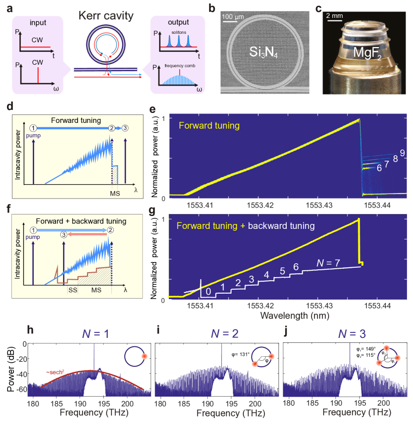
Observation of switching between dissipative Kerr soliton states by laser backward tuning. The principles of microresonator frequency comb generation and the formation of dissipative Kerr solitons (DKS) are shown in Fig.1(a). CW laser light is coupled to a high- optical resonator, where modulation instability (MI) and cascaded four-wave-mixing processes lead to the formation of a broadband frequency comb. In this work we study two microresonator platforms: on-chip ring microresonators Levy et al. (2010); Moss et al. (2013); Foster et al. (2011); Brasch et al. (2015) (Fig.1(b)) and crystalline resonators Ilchenko et al. (2004); Grudinin et al. (2006); Liang et al. (2011); Herr et al. (2014) (Fig.1(c)). The laser tuning technique was developed as an effective method to the formation of dissipative Kerr solitons Herr et al. (2014), in which the CW pump laser is tuned (from short to long wavelengths) over the cavity resonance, referred to as the “forward tuning”. Initially, the CW pump is in the blue-detuned regime. The cavity resonance is shifted due to the slow thermal and fast Kerr nonlinearity of the microresonator, resulting in a self-locking of the cavity resonance to the pump laser Braginsky et al. (1989); Carmon et al. (2004). In this regime the Kerr comb formation can be observed. The mechanism results in a triangular trace in the generated comb light, over the pump frequency detuning. When the pump is tuned over the cavity resonance, it enters the effectively red-detuned regime where multiple dissipative Kerr solitons (i.e. multiple-solitons) can be formed. The soliton state is accompanied with a step-like power trace in the generated comb light, where the step height corresponds to the number of solitons () inside the resonator. Transitions to states with lower number of solitons may also occur and the power trace will exhibit a characteristic steps Herr et al. (2014). Eventually, by stopping the pump laser tuning at a step while ensuring the thermal equlibrium in the resonator, stable multiple-soliton and even single soliton states can be accessed (Fig.1(d)). This forward tuning method was applied in , and silica resonators for single dissipative Kerr soliton generation Herr et al. (2014); Brasch et al. (2015); Yi et al. (2015b).
However, in on-chip microresonators, the thermal nonlinearity significantly impacts the soliton step pattern, such that single soliton states become rarely accessible with the forward tuning method. Figure 1(e) shows 200 overlaid experimental power traces of the generated comb light obtained in a microresonator in the forward tuning, in which only multiple-soliton states are stochastically accessed having (predominantly), 7, 8 or 9. Careful studies further reveal several common features in microresonators, irrespective of the employed pump power (see Supplementary Information (SI) for more details) and the laser tuning speed: (1) the distributions mostly consist of the traces with one step corresponding to high- multiple-soliton state; (2) the accessible step length decreases with decreasing ; (3) the number of generated solitons increases with increasing pump power. All of these imply that the single soliton state is not readily accessible in the forward tuning.
Remarkably, an additional laser tuning towards shorter wavelengths (“backward tuning”) provides a way to reliably access the single soliton state starting from an arbitrary multiple-soliton state. The result of this backward tuning sequence, shown in Fig.1(f), allows for successive extinction of intracavity solitons (soliton switching) down to the single soliton state (). Figure 1(g) shows one trace of the generated light of the microresonator, where switching from seven solitons to the single soliton is observed. Strikingly, the power trace of the generated comb light reveals a regular staircase pattern with equal stair length and height. The exact soliton number in each step can be precisely inferred from the step height. The pattern is almost identical over multiple experimental runs (using the same tuning speed and pump power) regardless of the initial soliton number . Each transition between multiple-soliton states occurs with the extinction of preferably one soliton at a time, which is confirmed by the relative positions of the intracavity solitons that are retrieved from the optical spectrum (cf. insets in Fig.1(h-j)).
In experiments, the backward tuning process must be adiabatic to induce the successive reduction of the soliton number: the thermal equilibrium is required at each multiple-soliton state. This prerequisite is satisfied by choosing a tuning speed much slower than the thermal relaxation rate that depends on the effective mode volume and the thermal diffusivity of a microresonator Fomin et al. (2005). For the employed microresonator the backward tuning speed is chosen , while the forward tuning speed is . In this way all soliton states () are deterministically accessible. In contrast to the robust backward tuning that enables successive extinction of intracavity solitons, the forward tuning in microresonators always leads to collective extinction of solitons.
The backward tuning was also studied in crystalline microresonators, where the successive soliton switching to the single soliton state is also achieved. In contrast to the platform, the single soliton state can directly be accessed with the forward tuning in microresonators Herr et al. (2014). Yet, this requires fine adjustments on the coupling, the pump power and the tuning speed. The backward tuning, on the other hand, is much more robust and significantly facilitates the generation of single soliton states for crystalline resonators.
The soliton switching in both and crystalline resonator, proves that the backward tuning represents a universal approach to the generation of a single soliton state in microresonators, provided that the thermal locking can be achieved.
Non-destructive probing of the soliton response. Dissipative Kerr solitons in microresonators represent stable and self-reinforcing intracavity light patterns resulting from double balance between pump and cavity losses, as well as chromatic dispersion and Kerr nonlinearity of the resonator. The key parameter of such soliton state is the effective laser frequency detuning that determines both the amplitude and the duration of soliton pulses Herr et al. (2014). This detuning is defined as , where indicates the frequency of a cavity resonance and is the pump laser frequency. In experiments the pump frequency is precisely controlled, but the resonance frequency is thermally shifted from the initial cold cavity resonance frequency , making it a priori not possible to evaluate the effective detuning. On the other hand, the absolute detuning can be introduced and measured as the position of the pump frequency relative to the fixed cold cavity resonance. It has been shown that solitons are supported within a certain range of the effective detuning Herr et al. (2014); Karpov et al. (2015), when the pump is effectively-red detuned (), which we refer to as the soliton existence range for a given constant input power.
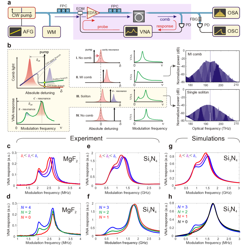
We developed a non-destructive soliton probing scheme that allows to track the effective detuning and extract the soliton number of microresonator frequency combs. The setup, presented in Fig.2(a), employs a pump laser, whose frequency is phase modulated using a vector network analyzer (VNA), that produces weak optical sidebands with sweeping frequency () in the range , which probe the state of the microresonator system. The complex modulation response to such probes is measured by the VNA.
This probing method enables to identify different stages in the generation of frequency comb, including the soliton formation, see Fig.2(b). First, when the pump is in the blue-detuned regime (), away from the cavity resonance, the modulation response on the VNA shows a Lorenzian-like resonance profile that corresponds to the cavity resonance with the peak position indicating . Second, when (forward) tuning the pump frequency into the cavity resonance, where the frequency comb in the chaotic MI regime is observed, the modulation response shows an asymmetric profile with the peak position being fixed, indicating the thermal and Kerr locking of the cavity resonance to the pump frequency. Third, when the frequency comb is in the soliton state, with the pump laser tuned in the soliton existence range in the red-detuned regime, the modulation response shows unexpectedly a double-resonance feature. Finally, when the pump frequency is tuned out of the soliton existence range where no comb is observed, the modulation response shows again a single, Lorenzian-like resonance similar to the first stage.
The double-resonance response that is observed in the presence of soliton states can be attributed to the superposition of weak continuous background and intense soliton pulses Herr et al. (2014). Due to different intensities each component induces a different Kerr shift to the cavity resonance which we can discriminate by the modulation probing. Since the pump is far detuned from the cavity resonance, the high-frequency peak in the modulation response corresponds to the cavity resonance that is slightly shifted by the CW component (-resonance). The peak position in this way indicates the effective detuning. On the other hand, the resonance shifted by solitons appears as the low-frequency peak (-resonance). The position of the -resonance is nearly fixed as it depends on the intensity of individual soliton, while the magnitude is related to the number of solitons ().
We applied the non-destructive soliton probing to both and microresonators. The double-resonance response is observed in both platforms when having soliton state frequency combs, and is investigated with different soliton number and pump detunings, see Fig.2(c-f). The response is qualitatively similar for both platforms. The peak position of the -resonance varies with the pump frequency (Fig.2(c,e)), while the -resonance frequency is practically fixed as predicted. The peak height of the -resonance linearly depends on the soliton number (Fig.2(d, f)). We also performed a theoretical analysis of the non-destructive soliton probing scheme, which confirms the double-resonance response of a soliton state (see Fig.2(g, h)).
The response of dissipative Kerr solitons to weak amplitude pump modulation was earlier numerically investigated in Matsko and Maleki (2015). While two peaks in the response were also numerically observed in that work (and attributed conceptually to Feshbach and relaxation oscillations in the presence of third order dispersion), the present work reveals the underlying physical origin of the soliton probing scheme, not requiring higher order dispersion. Moreover, phase modulation provides higher contrast of the modulation response.
As a way to extract the effective pump detuning , the probing technique enables to precisely track the process of microresonator frequency comb generation in experiments. In a soliton state, thermal drifts of the cavity resonance originating from various external sources may cause variations of . Based on the modulation response, the effective detuning can be monitored and adjusted (e.g. by tuning the pump frequency) in order to maintain the soliton state within the soliton existence range. In practice, feedback-locking of is possible, which allows for long-term operation of a soliton state in a microresonator.
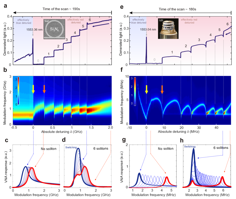
Deterministic switching of soliton states. We next investigate the transitions of soliton states in the laser backward tuning by applying the non-destructive soliton probing in microresonators. We first employ forward tuning in order to generate a multiple-soliton state with , and then we perform the slow backward tuning. The power trace of the generated light in the microresonator again shows the staircase pattern in the backward tuning, which corresponds to successive soliton switching from to the single soliton state (Fig.3(a)). The VNA traces are simultaneously recorded and continuously stacked in order to monitor the evolution of the modulation response during the process (see Fig.3(b)).
The experiments reveal a relationship between the evolution of modulation response and the soliton switching. Within each soliton step, the -resonance shifts towards the -resonance due to the decrease of the effective detuning when the laser is tuned backward. When the two resonances overlap, the amplitude of -resonance is significantly enhanced, leading to a high-intensity single-peak profile (Fig.3(d)). The phenomenon is also confirmed by the theory (cf. SI). The next moment after having such a response, soliton switching occurs, which results in the power drop in the generated light trace as one soliton is extinct (). After the switching, the -resonance abruptly separates from the -resonance. Meantime, while still being Kerr locked, the -resonance intensity is reduced to a lower level than the previous state, since the number of solitons is reduced by one. In the absence of solitons (), the -resonance equally is absent in the modulation response, but the -resonance is still present and captured (Fig.2(c)) .
The same measurement was carried out in resonators, see Fig.3(e-h). Similar switching dynamics as in microresonators are observed: (1) the power trace shows staircase profile of successive soliton switching; (2) the backward tuning shifts the VNA -resonance towards the -resonance; (3) soliton switching occurs with the overlap of - and -resonances and the enhancement of the -resonance intensity. However, there are several details which differ between and platforms. First, the optical quality factor of crystalline resonators () is three order of magnitude higher than for micro-rings (). The - and -resonances in the modulation response of crystalline resonator are better resolved as a result of the narrower linewidth. The laser tuning range in microresonators is , while that in resonators is . Second, after each soliton switching the resonator shows slower recoil of the -resonance than the microresonator. This is attributed to the distinct thermal relaxation of the two platforms. The resonator has a larger effective mode volume and physical size than the chip-scale micro-ring resonators such that the thermal relaxation time is longer. In the evolution of the modulation response of the resonator (Fig.3(f)), the recoil of the -resonance leaves curved trajectory while it is very abrupt in the microresonator (Fig. 3(b)).
The non-destructive soliton probing scheme combined with the backward tuning allows an understanding of the soliton switching dynamics in microresonators. The modulation response clearly predicts the switching and therefore provides a convenient tool to control the soliton states and induce switching on demand. In experiments, one can perform deterministic switching by tuning the pump frequency, while monitoring the effective laser frequency detuning revealed by the VNA response.
Thermally enabled transitions of soliton states. We attribute the successive soliton switching in backward tuning to the thermal nonlinearity of optical microresonators. Due to material absorption, the intracavity energy of a soliton state thermally shifts the cavity resonance via thermal expansion and thermal change of the refractive index: , where is the thermally induced resonance shift which is approximately (neglecting cross term) proportional to the energy of intracavity field:
| (1) |
where is the energy of the component, is the energy of one soliton and the number of solitons. Thus, the effective detuning can be expressed as . Physically, the soliton switching occurs when the laser backward tuning reduces the detuning to the bifurcation point of the system. This boundary value can be identified from the VNA trace and is represented by the position of the -resonance. After the switching, one soliton is extinct which decreases the energy in the cavity, and thereby reduces the thermal shift . This spontaneously stabilizes the system in a new soliton state, by effectively increasing the effective detuning. The process is reflected in the evolution of the modulation response (see Fig.3(b)) as a separation of - and -resonance after the switching. It should be also noted that the recoiled -resonance frequency is similar after each switching event, because the resonator loses approximately similar amount of energy. Overall, the thermal nonlinearity lifts the degeneracy of soliton states with respect to the pump frequency.
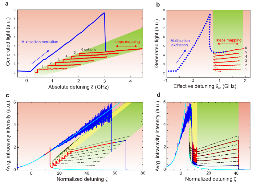
Full mapping of the soliton induced multi-stability diagram in optical microresonator. The pump backward tuning enables deterministic and successive soliton switching, opening access to soliton states . It is therefore possible to experimentally explore the soliton existence range in terms of the absolute and the effective detuning in each state, which to authors best knowledge has never been directly experimentally measured for cavity solitons of any kind. In terms of effective detuning, we express the soliton existence range as . The lower boundary is identified in the backward soliton switching: it corresponds to the frequency where the -resonance and the fixed -resonance overlap. In the studied microresonator under chosen pumping conditions this quantity is measured as . The upper detuning boundary of the soliton existence range can be explored for each soliton state when the pump laser is tuned forward until the soliton comb disappears. Based on the theory and standard LLE simulations, this detuning is expected to be identical for all states corresponding to different number of solitons Herr et al. (2014)(see Fig.4(d) and also SI), as the boundary of the energy balance of dissipative Kerr solitons. In experiments under the same pumping conditions such maximum effective detuning is found for all soliton states as , yet no clear feature in the modulation response enables to predict this maximum boundary.
Figure 4(a) displays a one-trace mapping of six steps of soliton states in microresonator as a function of the absolute pump frequency (wavelength) (i.e. the absolute detuning ). For each soliton step, we first tune the pump forward approaching the maximum detuning (), and then tune backward towards the soliton switching point () where the soliton state is switched from to . Since the thermally induced cavity resonance shift is included in the absolute frequency detuning, we observe that the soliton existence range in the absolute detuning is increasingly offset for a larger number of soliton. This creates the staircase pattern of the generated light and enables successive soliton switching. However, if the generated light trace is plotted with respect to the effective laser detuning () as done in Fig.4(b), it appears that all the soliton steps are stacked vertically within the range , which corresponds to the expected theoretical diagram when the thermal effect is neglected Herr et al. (2014).
We performed numerical simulations based on both LLE and coupled mode equations with the additional thermal relaxation equation included (cf. SI) which verify that the deterministic soliton switching is enabled by the thermal nonlinearity of the microresonator (Fig.4(c, d)). By including the thermal effects into numerical simulations, we are able to reproduce the staircase power trace, corresponding to the successive reduction of the soliton number in the backward pump tuning (cf. red curve in Fig.4(c)). Analytical power traces of soliton steps (black dashed lines) indicate soliton existence ranges for multiple-soliton states with different . They reveal a displacement of the soliton existence range between different soliton states (qualitatively similar to the measured in Fig.4(a)) as a consequence of the thermal nonlinearity.
When the thermal effects in simulations are “switched off”, soliton steps are well aligned and the soliton existence range is again degenerate with respect to the soliton number (), see Fig.4(d). No soliton switching is therefore observed in the backward tuning. Numerical simulation also revealed the soliton breather states that is considered as a intermediate state between the chaotic MI operation regime and the stable soliton state. In the breather state, the soliton pulse peak power and the pulse duration, as well as the average intacavity energy, will experience periodical oscillations. This induces thermal perturbations to the cavity resonance and initiates the soliton switching.
Discussion
We experimentally, numerically and analytically demonstrate the discovery that soliton states in a microresonator are not detuning degenerate, and can be individually addressed by laser detuning. We demonstrate that this effect is platform independent and can be used in a laser backward tuning process to achieve a successive reduction of the soliton number (). This deterministic switching is enabled by the thermal nonlinearity of the microresonator and provides a route to obtain a single soliton state from an arbitrary multiple-soliton state. We have shown non-destructive soliton probing technique, which enables to track the thermal impact of external perturbations of the system on its stability. The technique also allows to lock the soliton state against the impact of these perturbations and gives a clear insights of soliton dynamics inside the cavity. Combining this technique with the laser backward tuning allows for deterministic soliton switching and makes accessible any target multiple-soliton state in a predictable way. The results are in good agreement with analytical treatment of the soliton comb including thermal effects as well as numerical simulations, and can be applied to all Kerr nonlinear microresonators.
Methods
microresonators investigated in this work were fabricated using the Photonic Damascene process Pfeiffer et al. (2016). Microresonators have FSR of . A single mode “filtering” section was added to the micro-rings in order to suppress high-order modes Kordts et al. (2015). The dispersion parameters of the microresonators are measured using the frequency comb assisted laser spectroscopy method Del’Haye et al. (2009): , (where the resonance frequencies near are expressed in a series , where , is the mode number). Pumped resonance is at . Tuning speed for soft excitation is . Pump power is on a chip.
The detailed scheme of the experimental setup is presented in the Figure 2(a). The resonator is pumped with a CW laser light from an external-cavity diode laser amplified by an erbium-doped fiber amplifier (EDFA) to . The CW pump is coupled to the on-chip resonator using lensed fibers with coupling losses of per facet. For the soliton probing measurements electro-optical phase modulator (EOM) is placed before EDFA with additional polarization controller for adjusting input polarization. The pump frequency wavelength in the pump backward tuning is measured by a wave-meter with resolution of . For the long sweeps an arbitrary function generator is used. The output signal from the chip is split in several paths among OSA (for the measurements of combs spectra), oscilloscope (for the measurements of generated light by filtering out the pump with FBG) and a VNA receiver (for the measurements of and modulation response).
The crystalline resonator was fabricated by diamond turning of a cylinder blank and subsequent hand polishing to achieve high (linewidth ). The diameter of 5 mm yields a FSR GHz. The dispersion parameters at the pump wavelength of are: , . The pump laser (fiber laser, wavelength ; short-term linewidth ) is amplified to . The relative laser frequency is monitored by counting the heterodyne beat between the pump laser and a reference laser stabilized to an ultra-stable cavity. The light is evanescently coupled to a WGM with a tapered optical fiber.
References
- Del’Haye et al. (2007) P. Del’Haye, A. Schliesser, O. Arcizet, T. Wilken, R. Holzwarth, and T. J. Kippenberg, Nature 450, 1214 (2007).
- Kippenberg et al. (2011) T. J. Kippenberg, R. Holzwarth, and S. Diddams, Science 332, 555 (2011).
- Kippenberg et al. (2004) T. J. Kippenberg, S. M. Spillane, and K. J. Vahala, Phys. Rev. Lett. 93, 083904 (2004).
- Savchenkov et al. (2004) A. A. Savchenkov, A. B. Matsko, D. Strekalov, M. Mohageg, V. S. Ilchenko, and L. Maleki, Phys. Rev. Lett. 93, 243905 (2004).
- Del’Haye et al. (2011) P. Del’Haye, T. Herr, E. Gavartin, M. L. Gorodetsky, R. Holzwarth, and T. J. Kippenberg, Phys. Rev. Lett. 107, 063901 (2011).
- Okawachi et al. (2011) Y. Okawachi, K. Saha, J. Levy, H. Wen, M. Lipson, and A. Gaeta, Opt. Lett. 36, 3398 (2011).
- Herr et al. (2012) T. Herr, K. Hartinger, J. Riemensberger, C. Wang, E. Gavartin, R. Holzwarth, M. L. Gorodetsky, and T. J. Kippenberg, Nat. Photon. 6, 480 (2012).
- Ferdous et al. (2011) F. Ferdous, H. Miao, D. E. Leaird, K. Srinivasan, J. Wang, L. Chen, L. T. Varghese, and A. M. Weiner, Nature Photon. 5, 770 (2011).
- Papp et al. (2013) S. Papp, P. Del’Haye, and S. Diddams, Opt. Express 21, 17615 (2013).
- Herr et al. (2014) T. Herr, V. Brasch, J. D. Jost, C. Wang, M. Kondratiev, M. L. Gorodetsky, and T. J. Kippenberg, Nat. Photon. 8, 145 (2014).
- Brasch et al. (2015) V. Brasch, M. Geiselmann, T. Herr, G. Lihachev, M. H. P. Pfeiffer, M. L. Gorodetsky, and T. J. Kippenberg, Science (2015), 10.1126/science.aad4811.
- Karpov et al. (2015) M. Karpov, H. Guo, A. Kordts, V. Brasch, M. H. P. Pfeiffer, M. Zervas, M. Geiselmann, and T. J. Kippenberg, arXiv:1506.08767 (2015).
- Yi et al. (2015a) X. Yi, Q.-F. Yang, K. Y. Yang, M.-G. Suh, and K. Vahala, Optica 2, 1078 (2015a).
- Ideguchi et al. (2013) T. Ideguchi, S. Holzner, B. Bernhardt, G. Guelachvili, N. Picqué, and T. W. Hänsch, Nature 502, 355 (2013).
- Pfeifle et al. (2014) J. Pfeifle, V. Brasch, M. Lauermann, Y. Yu, D. Wegner, T. Herr, K. Hartinger, P. Schindler, J. Li, D. Hillerkuss, R. Schmogrow, C. Weimann, R. Holzwarth, W. Freude, J. Leuthold, T. J. Kippenberg, and C. Koos, Nat. Photon. 8, 375 (2014).
- Pfeifle et al. (2015) J. Pfeifle, A. Kordts, P. Marin, M. Karpov, M. H. P. Pfeiffer, V. Brasch, R. Rosenberger, J. Kemal, S. Wolf, W. Freude, T. J. Kippenberg, and C. Koos, in CLEO: 2015 Postdeadline Paper Digest (Optical Society of America, 2015) p. JTh5C.8.
- Papp et al. (2014) S. Papp, K. Beha, P. Del’Haye, F. Quinlan, H. Lee, K. Vahala, and S. Diddams, Optica 1, 10 (2014).
- Leo et al. (2010) F. Leo, S. Coen, P. Kockaert, S.-P. Gorza, P. Emplit, and M. Haelterman, Nat. Photon. 4, 471 (2010).
- Liang et al. (2015) W. Liang, D. Eliyahu, V. Ilchenko, A. Savchenkov, A. Matsko, D. Seidel, and L. Maleki, Nat. Commun. 6 (2015).
- Grudinin and Yu (2015) I. S. Grudinin and N. Yu, in Laser Resonators, Microresonators, and Beam Control XVII, Proceedings of SPIE, Vol. 9343 (2015) pp. 93430F–93430F–9, 10.1117/12.2085420.
- Jang et al. (2015) J. K. Jang, M. Erkintalo, S. Coen, and S. G. Murdoch, Nature communications 6 (2015).
- Chembo and Yu (2010) Y. K. Chembo and N. Yu, Phys. Rev. A 82, 033801 (2010).
- Chembo and Menyuk (2013) Y. Chembo and C. Menyuk, Phys. Rev. A 87, 053852 (2013).
- Coen et al. (2013) S. Coen, H. Randle, T. Sylvestre, and M. Erkintalo, Opt. Lett. 38, 37 (2013).
- Godey et al. (2014) C. Godey, I. Balakireva, A. Coillet, and Y. Chembo, Phys. Rev. A 89, 063814 (2014).
- Lamont et al. (2013) M. Lamont, Y. Okawachi, and A. Gaeta, Opt. Lett. 38, 3478 (2013).
- Levy et al. (2010) J. Levy, A. Gondarenko, M. Foster, A. Turner-Foster, A. Gaeta, and M. Lipson, Nat. Photon. 4, 37 (2010).
- Moss et al. (2013) D. Moss, R. Morandotti, L. Gaeta, and M. Lipson, Nat. Photon. 7, 597 (2013).
- Foster et al. (2011) M. A. Foster, J. S. Levy, O. Kuzucu, K. Saha, M. Lipson, and A. L. Gaeta, Opt. Express 19, 14233 (2011).
- Ilchenko et al. (2004) V. S. Ilchenko, A. A. Savchenkov, A. B. Matsko, and L. Maleki, Phys. Rev. Lett. 92, 043903 (2004).
- Grudinin et al. (2006) I. S. Grudinin, A. B. Matsko, A. A. Savchenkov, D. Strekalov, V. S. Ilchenko, and L. Maleki, Opt. Commun. 265, 33 (2006).
- Liang et al. (2011) W. Liang, A. A. Savchenkov, A. B. Matsko, V. S. Ilchenko, D. Seidel, and L. Maleki, Opt. Lett. 36, 2290 (2011).
- Braginsky et al. (1989) V. B. Braginsky, M. L. Gorodetsky, and V. S. Ilchenko, Physics Letters A 137, 393 (1989).
- Carmon et al. (2004) T. Carmon, L. Yang, and K. Vahala, Opt. Express 12, 4742 (2004).
- Yi et al. (2015b) X. Yi, Q.-F. Yang, K. Y. Yang, M.-G. Suh, and K. Vahala, Optica 2, 1078 (2015b).
- Fomin et al. (2005) A. E. Fomin, M. L. Gorodetsky, I. S. Grudinin, and V. S. Ilchenko, J. Opt. Soc. Am. B 22, 459 (2005).
- Matsko and Maleki (2015) A. B. Matsko and L. Maleki, Phys. Rev. A 91, 013831 (2015).
- Pfeiffer et al. (2016) M. H. P. Pfeiffer, A. Kordts, V. Brasch, M. Zervas, M. Geiselmann, J. D. Jost, and T. J. Kippenberg, Optica 3, 20 (2016).
- Kordts et al. (2015) A. Kordts, M. Pfeiffer, H. Guo, V. Brasch, and T. J. Kippenberg, arXiv:1511.05381 (2015).
- Del’Haye et al. (2009) P. Del’Haye, O. Arcizet, M. L. Gorodetsky, R. Holzwarth, and T. J. Kippenberg, Nat. Photon. 3, 529 (2009).
Acknowledgements
Acknowledgements.
Acknowledgements. This publication was supported by Swiss National Science Foundation (SNF) as well as Contract W31P4Q-14-C-0050 from the Defense Advanced Research Projects Agency (DARPA), Defense Sciences Office (DSO). This material is based upon work supported by the Air Force Office of Scientific Research, Air Force Material Command, USAF under Award No. FA9550-15-1-0099. This publication was supported by funding from the European Space Agency (ESA), European Space Research and Technology Centre (ESTEC). G.L., V.E.L. and M.L.G. were supported by the Ministry of Education and Science of the Russian Federation project 4.585.21.0005. The authors gratefully acknowledge valuable discussions with Michael Geiselmann, Martin H.P. Pfeiffer, John D. Jost and Victor Brasch. All samples were fabricated and grown in the Center of MicroNanoTechnology (CMi) at EPFL.Authors contributions
M.K. designed and performed the experiments and analyzed the data. H.G. conceived and initiated the numerical simulations. E.L. performed experiments in microresonators and analyzed the data. A.K. fabricated the samples and M.P. developed the fabrication method. G.L. and V.E.L. assisted in simulations. M.L.G. developed the theory and performed the simulations. M.K., H.G., E.L., M.L.G., T.J.K. discussed all data in the manuscript. M.K. and H.G. wrote the manuscript, with input of E.L., M.L.G., T.J.K. T.J.K. supervised the project.