Giant permanent dipole moment of 2D excitons bound to a single stacking fault
Abstract
We investigate the magneto-optical properties of excitons bound to single stacking faults in high-purity GaAs. We find that the two-dimensional stacking fault potential binds an exciton composed of an electron and a heavy-hole, and confirm a vanishing in-plane hole -factor, consistent with the atomic-scale symmetry of the system. The unprecedented homogeneity of the stacking-fault potential leads to ultra-narrow photoluminescence emission lines (with full-width at half maximum ) and reveals a large magnetic non-reciprocity effect that originates from the magneto-Stark effect for mobile excitons. These measurements unambiguously determine the direction and magnitude of the giant electric dipole moment () of the stacking-fault exciton, making stacking faults a promising new platform to study interacting excitonic gases.
Introduction.
The stacking fault (SF), a planar, atomically thin defect, is one of the most common extended defects in zinc-blende, wurtzite, and diamond semiconductors. A fundamental understanding of the SF potential is important for determining how the defect affects semiconductor device performance Guha et al. (1993); Colli et al. (2003), engineering heterostructures based on crystal phase Caroff et al. (2011); Akopian et al. (2010); Assali et al. (2013), and providing a new two-dimensional (2D) platform for fundamental physics Butov et al. (2002a); High et al. (2009). Here we report on excitons bound to large-area, single SFs in high-purity GaAs, a unique system where SFs are easily isolated with far-field optical techniques. The atomic smoothness of the potential and extreme perfection of the surrounding semiconductor result in ultra-high optical homogeneity (). This enables optical resolution of the SF exciton fine-structure and thus direct measurement of the giant built-in dipole moment () via the magneto-Stark effect. These results indicate that the extremely-homogeneous SF potential may be promising for studies of many-body excitonic physics, including coherent phenomena Snoke et al. (2002); Butov et al. (2002b); Shilo et al. (2013), spin currents High et al. (2013), superfluidity Fogler et al. (2014), long-range order Gorbunov and Timofeev (2006); Snoke (2011); Nelsen et al. (2009); Balili et al. (2009); High et al. (2012), and large optical nonlinearities Amo et al. (2010); Nguyen et al. (2013); Kammann et al. (2012).
Stacking fault photoluminescence.
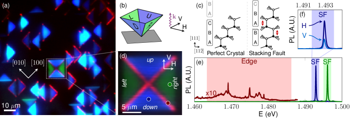
Figure 1(a) shows a spectrally resolved confocal scan of SF structures in a GaAs epilayer, excited with an above band-gap laser ( eV, 1.5 K) sfs . The image is colored red, green or blue according to three characteristic emission bands shown in Fig. 1e. The narrow-band PL at 1.493 and 1.496 eV originates from excitons, electron-hole pairs, bound to the 2D SF potential Kasai and Kawata (1998); Lähnemann et al. (2014). The sample consists of a 10 GaAs layer on 100 nm AlAs on a 5 nm/5 nm AlAs/GaAs (10) superlattice grown directly on a semi-insulating (100) GaAs substrate. Stacking fault structures nucleate near the substrate-epilayer interface during epitaxial growth sfs .
The physical origin of the potential can be understood from the atomic structure of the SF defect: the lattice-plane ordering in the [111] direction of zinc-blende is modified by subtracting a layer (intrinsic SF, see Fig. 1c) or adding a layer (extrinsic SF). The intrinsic SF can be viewed as a monolayer of wurtzite (AB AB stacking) surrounded by zinc-blende (ABC ABC stacking) Algra et al. (2008); Caroff et al. (2011). Due to the band offset Belabbes et al. (2012); Spirkoska et al. (2009); Heiss et al. (2011) and spontaneous polarization at the stacking fault Lähnemann et al. (2012), electrons and/or holes are attracted to the SF plane. While useful for physical motivation, this bulk phase change model must be taken with caution when applied to atomically thin SFs, which can deviate from simple theory Vainorius et al. (2015). Here, however, we find that single SFs in bulk GaAs bind excitons, confirming that the potential is attractive for at least one carrier.
In the confocal scan in Fig. 1(a), most of the SF defects appear as single triangles, which we identify as a pair of nearby SFs Fung et al. (1997); Wang et al. (2000). Because the binding energy of excitons to a pair of SFs depends on the distance between the SFs Corfdir and Lefebvre (2012), the PL emission energy from excitons bound to these structures has a high variability of meV between structures. Strikingly, this inhomogeneity disappears when four SFs grow in an inverted pyramid structure consisting of four well-isolated SF planes [Fig. 1(b)], which we refer to as up, down, left and right Kakibayashi et al. (1984). The full width at half-maximum (FWHM) of the SF PL line in our sample is eV at zero magnetic field sfs , somewhat narrower than excitonic lines associated with stacking faults in previous work Kasai and Kawata (1998); Komatsu (1988). In comparison, the narrowest reported linewidth for a GaAs/AlGaAs quantum well is 130 eV Poltavtsev et al. (2014), while PL linewidths from analogous zinc-blende/wurtzite quantum discs in nanowires range from meV Heiss et al. (2011); Graham et al. (2013); Pal et al. (2008); Signorello et al. (2014). This unprecedented homogeneity allows us to resolve the SF-bound exciton fine structure
Nature of hole in SF exciton.
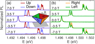
Experimentally, we determine that the SF exciton is composed of an electron and a heavy-hole using polarization resolved PL, consistent with the atomic-scale symmetry of the system sfs . For linearly polarized light incident from above (along the [001] axis), the largest overlap between the light polarization and the in-SF-plane heavy-hole dipole occurs when exciting and collecting along the H direction for the down SF [Fig. 1(d)], in agreement with our experimental data [Fig. 1(f)]. On the other hand, the main dipole moment for the light-hole exciton is along the SF normal, which would give rise to a maximum signal at V polarization, contrary to what is observed. Further, we also note that no hole Zeeman splitting is observed for in-plane magnetic fields up to 7 T (Fig. 2). This observation is fully consistent with our symmetry analysis, which finds that -linear splitting for in-plane fields is forbidden for heavy-holes but allowed for light-holes sfs . The substantial separation of the heavy- and light-hole states prevents their magnetic-field induced mixing, in line with experiments on GaAs nanowires Spirkoska et al. (2012); sfs .
Non-reciprocal photoluminescence.
PL from SFs shows a remarkable non-reciprocity with in-plane applied magnetic field: Figure 2(a) shows that the PL detected in linear polarization from the up SF occurs at a different energy depending on whether the magnetic field is parallel (positive) or antiparallel (negative) to the axis. Interestingly, the down SF demonstrates the opposite behavior. Such an asymmetric behavior of the PL is surprising because in general, time reversal symmetry makes and equivalent 111Our sample is non-magnetic and we use linearly polarized light to avoid dynamic polarization of nuclear spins.. The observed non-reciprocal behavior of the PL spectrum with respect to inversion is only possible if the PL arises from moving excitons. In this case, time reversal changes the direction of both the magnetic field and the exciton wavevector .
Based on the point symmetry of the SF and time reversal invariance, the effective Hamiltonian for an exciton moving in the presence of an in-SF-plane magnetic field is
| (1) |
where is the electron -factor, is the Bohr magneton, are the electron spin Pauli matrices, is a parameter describing the excitonic diamagnetic shift, and is a constant responsible for the non-reciprocal effect sfs . In Eq. (1) we only retain 1st- and 2nd-order terms in and use a frame of axes related to the SF plane: is the SF normal, and . Each symmetry-derived term in Eq. (1) manifests itself in the energetic shift of the SF PL lines with magnetic field (Fig. 2). The first term is the electron Zeeman effect and gives rise to the doublets visible at 7 T, since an electron with a particular spin projection can recombine with the corresponding hole. The second term is the exciton diamagnetic shift, arising from the magnetic-field-induced shrinking of the exciton wavefunction Knox (1963). The last term is the magneto-Stark effect, which, as we show below, quantitatively explains the non-reciprocal PL spectra.
The experimental geometry, Fig. 1(b), is such that only light emitted normal to the sample surface is collected. For a high quality 2D potential, in-plane exciton momentum is transferred to the photon during recombination, as depicted in Fig. 3(a). This conservation of momentum implies
| (2) |
where is the angle between the SF normal and the emitted photon momentum inside the semiconductor, Fig. 3(a), is the photon frequency, is the refractive index and the speed of light. Thus, the collected SF PL arises only from excitons with a specific center of mass momentum 222Experimentally, the objective lens collects luminescence from a range of angles. In our system, light is collected from excitons momenta within 7% of in Eq. (2).. The last term in Eq. (1) provides, for a fixed (Eq. 2), an odd in contribution to the overall PL energy shift, giving rise to a magnetic non-reciprocity effect. It is worth noting that the up and down SFs are related by a mirror reflection in the (110) plane and such a reflection is accompanied by , resulting in the opposite behavior of up and down PL spectra observed in Fig. 2(a).
Magneto-Stark effect.
The physical origin of the non-reciprocal PL is the magneto-Stark effect, the interaction of a moving exciton’s electric dipole moment with a magnetic field Gross et al. (1961); Thomas and Hopfield (1961). The effect can be understood with a relativistic argument: motion with velocity through a magnetic field gives rise to an electric field in the moving frame of reference, where is the exciton mass in translational motion and the speed of light. Since for the SF, and directions are not equivalent, the SF-bound exciton has a non-zero dipole moment , where is the elementary charge, and is the average separation between the hole and electron along the -axis. The Stark effect in the exciton’s reference frame thus becomes the magneto-Stark effect:
| (3) |
in agreement with Eq. (1) with , see Ref. Knox (1963); sfs for formal derivation.
Physically, the dipole moment of a SF bound exciton is a consequence of symmetry breaking and spontaneous polarization similar to that in zinc-blende/wurtzite heterostructures Lähnemann et al. (2014); Jahn et al. (2012). The hole in the exciton is presumably localized in the SF plane while the electron is weakly bound via the Coulomb interaction. The spontaneous polarization shifts the electron cloud to one side of the SF, resulting in a giant excitonic dipole moment.
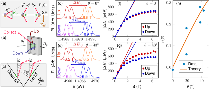
Equations (1)-(3) predict that the asymmetric energy shift of exciton PL is linearly related to the in-plane wavevector . Since the angle of light collection determines the exciton momentum [Eq. (2)], we test the applicability of the model by recording spectra of the up and down SFs as a function of the collection angle and magnetic field [Fig. 3(b)]. The collection angle is related to the emission angle from the up/down SF by , where is the angle the SF normal makes with [001] [Fig. 3(c)].
In this experiment, we modified the collection angle by mounting the sample at different angles. Since the sample was removed from the cryostat to change the angle, different SF pyramids were used at different angles. This does not introduce artifacts because of the extreme similarity of different SFs, which have a standard deviation of line-center energies of only 57 eV, less than the linewidth. Spectra were acquired with ranging from T to 6.5 T on the up and down SFs. We fit the spectra to one or a sum of two Voigt function(s) depending on whether the electron Zeeman splitting is resolved. The singlet or doublet line center is denoted . The part of the exciton energy odd with magnetic field is found by computing
| (4) |
It follows from Eq. (3) that the asymmetric shift is
| (5) |
Thus the proportionality constant of vs. provides a measurement of the SF exciton’s built-in dipole moment. The experimental values and first-order theory for are shown in Fig. 3(f)-(g). Further, the ratio
| (6) |
depends (to first order in ) only on the experimental geometry and the index of refraction: vanishes for collection angle and increases as a function of [Fig. 3(h)]. We obtain good agreement between calculated experimentally from the slope of without any fit parameters [Fig. 3(h)].
Further, by fitting with a -linear function, we can estimate the dipole moment of the exciton . The main uncertainties result from the accuracy of the -linear fit and the value of the in--plane heavy-hole mass, which depends on the details of the SF potential sfs . The exciton mass can be roughly estimated as , the sum of the bulk-GaAs in--plane heavy-hole mass and the isotropic electron mass, where is the free electron mass. In addition, we note the magneto-Stark induced splitting saturates at high fields [Fig. 3(f,g)], possibly due to a decreased exciton dipole moment from the magnetic-field-induced shrinking of the exciton wavefunction. Future work will investigate exciton confinement potentials consistent with the observed dipole moment, diamagnetic shift and saturation of the magneto-Stark effect. A microscopic understanding of the confinement potential may enable predictions for the binding potential and excitonic dipole moment for SFs in other semiconductors.
Conclusion.
We have shown that SFs in GaAs are an almost perfect 2D potential which binds heavy-hole excitons. These excitons freely propagate in the SF plane, a conclusion confirmed via the magneto-Stark effect. Further, an asymmetry of the SF potential induces a giant dipole moment of the SF-bound exciton. Such excitons could be useful for studying the many-body physics of interacting dipoles. In conventional excitonic systems, typical electron-hole separations are on the order of several nm Butov et al. (2002a); Warburton et al. (2002), whereas the SF-bound exciton has a gigantic electron-hole separation of 10 nm and the possibility to modify this value with an applied field. In addition, the ultra-narrow linewidths in the SF system will allow the small energy shifts present in many-body interactions to be observed. As a rough estimate, the interaction energy of two such dipoles will exceed the SF FWHM of 77 eV when the exciton density is greater than 230 . Using a wavefunction size of approximately 10 nm, the critical density for exciton overlap in the 2D potential is 10 000 . Therefore, the SF-bound exciton system could show sizable dipole-dipole interactions and may demonstrate coherent phenomena at reasonable exciton densities.
Acknowledgements.
This material is based upon work supported by the National Science Foundation under Grant Number 1150647 and the National Science Foundation Graduate Research Fellowship under grant number DGE-1256082, and in part by the State of Washington through the University of Washington Clean Energy Institute. The Ioffe team has been partially supported by RFBR, RF President grant No. MD-5726.2015.2 and Dynasty foundation. A.K.R., A.L., and A.D.W. acknowledge partial support of Mercur Pr-2013-0001, DFG-TRR160, BMBF - Q.com-H 16KIS0109, and the DFH/UFA CDFA-05-06. We would like to acknowledge helpful discussions with John Schaibley, Pasqual Rivera, Xiaodong Xu, David Cobden and Matt McCluskey.
Supplemental Materials: Fundamental properties of 2D excitons bound to single stacking faults in GaAs
S1 Stacking Fault formation
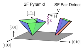
Stacking fault (SF) structures can grow from the substrate-epilayer interface during epitaxial growth Kakibayashi et al. (1984); Chai et al. (1985). In the present work, SFs form in a 10 GaAs layer grown by molecular beam epitaxy with room temperature electron density and mobility . The entire structure consists of the 10 GaAs layer on 100 nm AlAs on a 5 nm/5 nm AlAs/GaAs (10) superlattice grown directly on a semi-insulating (100) GaAs vertical gradient freeze substrate (Wafer Technology Ltd), started with AlAs. The sample was grown at a pyrometer temperature of 600∘C with the relatively low As4 beam equivalent pressure of , measured by a flux tube. The growth rate was 0.7 ML/s for the GaAs and 0.35 ML/s for the AlAs. Oxide removal before growth was performed at 620∘C under As flux. This growth procedure resulted in oval defects in the sample surface, a feature commonly associated with stacking faults Kasai and Kawata (1998); Kakibayashi et al. (1984); Haverkort et al. (1992); Chai et al. (1985). We observe two types of stacking fault defects, a SF pyramid and a SF pair defect, shown in Fig. S4. The size of the pyramid structure (14.1 m top edge in Fig. 1a) is consistent with stacking faults that nucleate near the substrate-epilayer interface and grow along planes through the 10 m thick epilayer.
S2 Photoluminescence spectroscopy system
The sample is excited with a continuous wave Sirah Matisse Ti:Sapphire laser. The laser is focused to a spot size of 1 m on the sample using an aspheric lens (numerical aperture ) mounted inside a liquid helium immersion cryostat (Janis). Coarse positioning of the sample was performed with slip-stick positioners (Attocube). For confocal scanning, spatial selectivity is achieved with a pinhole in the intermediate image plane and a scanning mirror to raster the excitation and collection spot over the sample. The photoluminescence (PL) is imaged on a spectrometer (Andor).
S3 Stacking fault photoluminescence linewidth
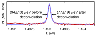
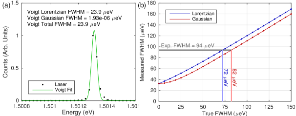
Figure S5 shows a high resolution PL spectrum of the SF. In order to extract the true PL linewidth, we need to take into account the spectral resolution of our setup. The spectrometer instrument resolution is found by taking a spectrograph of a narrow band Ti:Sapphire laser and fitting to a Voigt function, see Fig. S6(a). We find that neither a Gaussian nor a Lorentzian accurately describe the spectral point spread function, so we use a Voigt fit. For spectral lines that are nearly as narrow as the spectrometer FWHM (full width at half maximum), the measured FWHM will be wider than the true FWHM. Figure S6(b) shows the FWHM of a line obtained by the convolution of a Lorentzian or Gaussian spectral lineshape with the spectrometer response function. For example, a measured linewidth of 94 eV corresponds to a true linewidth of 72 or 82 eV, depending on whether the true lineshape is assumed to be Lorentzian or Gaussian. Hence, to evaluate the intrinsic linewidth of the SF emission we fit the spectrum in Fig. S5 with a weighted Lorentzian and use the deconvolution procedure [Fig. S6(b)] to obtain an intrinsic PL linewidth of only eV. Here, the uncertainty combines the original fit uncertainty and the uncertainty of the deconvolution procedure.
S4 Magneto-Stark Hamiltonian
Microscopically, the magneto-Stark effect can be derived from the Hamiltonian for an electron and hole in a magnetic field :
| (S7) |
where () is the wavevector of the electron (hole), () is the effective mass of the electron (hole) and the vector potential is . The Coulomb interaction between the electron and the hole as well as the SF potential are omitted in Eq. (S7) for brevity. We use the standard definition of center of mass (COM) and relative coordinates
| (S8) | ||||
where . With these substitutions, Eq. S7 becomes
| (S9) | ||||
where Knox (1963). The first term is the COM kinetic energy of the exciton. The second term is the kinetic energy associated with the electron-hole relative motion. The third term describes the magneto-Stark effect for the exciton COM motion. The fourth term describes the orbital Zeeman effect Knox (1963). The fifth term is the harmonic potential created by the magnetic field which produces the diamagnetic shift and would produce Landau quantization for higher magnetic fields. The COM magneto-Stark term is the same as Eq. (3) in the main text, derived from relativistic arguments.
S5 Heavy hole – light hole splitting
The possible carrier spin states entering into the SF exciton can be predicted on general symmetry considerations. Due to spin orbit coupling, the valence band in bulk GaAs splits into the heavy-hole/light-hole () bands and split-off () band. At the point, the heavy-hole (HH) and light-hole (LH) bands are degenerate and transform according to the four-dimensional irreducible spinor representation of the point symmetry group Bir and Pikus (1974), see Refs. Koster et al. (1963); Dresselhaus et al. (2008) for notations.
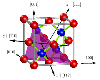
A SF oriented in one of the planes possesses the lower point symmetry, as illustrated in Fig. S7. The symmetry group contains six symmetry operations: E (identity), (rotation by about ), (rotation by about ), (reflection ), (), and (). These operations are depicted in Fig. S8. We note that the SF symmetry group is different from the symmetry of wurtzite Birman (1959).
When a SF is introduced into a zinc-blende crystal, the degeneracy of the valence and conduction band edges could be lifted. The compatibility analysis shows that the conduction band edge transforms according to the two-dimensional irreducible representation of the C3v point group, i.e. the conduction band does not split. On the other hand, the degeneracy of the valence band is lifted: the irreducible representation of Td decomposes into of C3v. The two degenerate states transform as the spinors (or ), where signifies the basic function for angular momentum and angular momentum -component . The and hole states transform as linear combinations the spinors and , see Table I. At and , the two states and are guaranteed to be degenerate by time reversal symmetry Dresselhaus (1955); Herring (1937); Elliott (1954). It follows that the levels of excitons bound to a SF are split into sublevels of symmetry and where the superscripts refer to the conduction and valence bands. For convenience, the former and latter excitonic states are called the light- and heavy-hole excitons, or the LH and HH excitons, irrespective of the relation between the exciton binding energy and the splitting between the HH and LH sublevels.
The experimental data imply that the in-plane hole -factor in the ground exciton state is negligible. This is exactly true for the HH exciton at zero magnetic field and zero wavevector . This implies that the splitting is high enough to prevent the mixing between the LH and HH sublevels induced by the finite value of realized in the experiment and by the applied magnetic field, .
In order to confirm that the SF splits HH and LH states, we we can estimate whether the HH-LH splitting is much greater than interactions which mix HH and LH. The magnetic-field-induced HH-LH mixing can be estimated by using the hole Zeeman Hamiltonian
| (S10) |
where is the Bohr magneton, is the magnetic Luttinger parameter on the order of unity, are the matrices of the angular momentum 3/2 operator, and we neglect a weak cubic anisotropy Sallen et al. (2011). According to Eq. (S10), the magnitude of the Zeeman HH-LH coupling matrix element at the maximum field of 7 T is meV. As for the HH-LH mixing caused by the nonzero value of , we note that the maximum exciton wavevector measured in our system is 5 m-1. In this case the terms of the Luttinger-Kohn Hamiltonian that couple the HH and LH excitons have magnitudes less than 2 eV Bir and Pikus (1974). Thus, we conclude that no significant mixing occurs if the splitting is greater than a few meV. The lack of significant HH-LH mixing in our experiments is in agreement with the HH-LH splitting of 16 meV estimated for interface excitons in polytypic zinc-blende/wurtzite GaAs nanowires Spirkoska et al. (2012).
| Basis Functions | |||||||
|---|---|---|---|---|---|---|---|
In order to determine the dipole moment of the SF exciton using Eq. 5, it is necessary to estimate the in-plane exciton effective mass, the sum of the electron and hole in-plane effective masses. While the electron mass is isotropic in GaAs, the effective in-plane hole mass depends on the detailed nature of the stacking fault potential. We note here that HH-LH mixing can affect the in-plane HH effective mass Ivchenko and Pikus (1997). Using second-order perturbation theory, we obtain:
| (S11) |
where the summation goes over all the light-hole states (both bound and continuum), denotes the ground subband HH envelope function along the axis and denote the LH envelopes and and are the Luttinger parameters Bir and Pikus (1974). The sum in Eq. S11 is sensitive to the details of the HH and LH envelope functions as well as to the energy positions of the size-quantized levels Ivchenko and Pikus (1997); Ikonic´ et al. (1992).
The estimate of the exciton dipole moment involves the exciton’s effective mass, , see Eq. (5), where and are the in-plane effective masses of the hole and electron. The electron effective mass is isotropic and therefore its in-plane value is . Due to the anisotropy of the hole effective mass and the unknown extent of HH-LH coupling, determining the correct value of requires a complex calculation, which we do not perform here. However, we can estimate the HH effective mass using some simple arguments. If HH-LH coupling is neglected, the in-plane heavy hole mass is that of a heavy-hole in the (111) plane, Ikonic´ et al. (1992). Another estimate of the in-plane heavy hole mass can be made from the spatially averaged heavy-hole mass of . We will use the lower value to estimate the dipole moment, and the higher value to estimate the error in our measurement of the dipole moment. This conservative procedure yields the minimum possible value of the dipole moment.

S6 Hamiltonian by symmetry
The form of the Hamiltonian describing the SF-bound exciton state can be derived based on the symmetry of the SF system. Specifically, we would like to find terms of the Hamiltonian that are odd with magnetic field and can thus explain the magnetic non-reciprocity data.
It is first necessary to find how the symmetry operations affect a vector, such as a position vector , and a pseudo-vector, such as magnetic field . In free space, and transform according to the and irreducible representations, where denotes parity with respect to space inversion. Making use of the compatibility tables for point symmetry, one can readily check that , while . Taking into account that under rotations the components of polar and axial vectors transform identically and making use of Fig. S8 we find that and transform according to the irreducible representations and , respectively, while the pairs and form equivalent bases of the two-dimensional irreducible representation of , see Table 1.
To apply the method of invariants, we need to establish transformation rules for the basic matrices acting in the spin subspaces of electrons and heavy-holes. We introduce basic electron matrices (the unit matrix) and (Pauli matrices) acting in the basis of electron spinors. The decomposition indicates the ways in which the basic electron spin matrices transform. By calculating the effect of the symmetry operators on the matrices, one finds that is invariant, transforms according to and form a basis of the two-dimensional irreducible representation with and transforming equivalently to and respectively (Tab. 1). The basic matrices for the light-hole doublet transform in exactly the same way.
By contrast, the heavy-hole spin doublet transforms according to the reducible representation . The direct product
| (S12) |
indicates that among the four basic matrices, , acting in the space , two are invariant and two transform as Sallen et al. (2011). Taking into account that at the mirror reflection the matrix does not change sign, we find that and transform according to (note that changes its sign under time reversal whereas does not), while , transform according to , see Tab. 1 and Ref. Sallen et al. (2011).
Using the transformation properties of the relevant basis functions (Tab. 1), we can build the effective Hamiltonian. Any valid term of the Hamiltonian must transform as the identity representation and be even under time reversal. In order to know which combinations of basis functions transform as , we use the product rules for irreducible representations. From this information, we can build the linear in Hamiltonian. For the electron, this analysis produces the result that the in-plane and out-of-plane -factors are potentially different:
| (S13) |
For the heavy holes, the Hamiltonian takes the form Sallen et al. (2011):
| (S14) |
Eqquation S14 implies that the heavy hole has a zero in-plane -factor, and that an out-of-plane component creates a tilted effective field with a spin precession vector lying in the plane. We note that the atomic-scale symmetry of the SF makes the two in-plane directions and inequivalent.
The magneto-Stark Hamiltonian can be derived by symmetry using a similar procedure. The combination of the two irreducible representations and contains an invariant representation, leading to the Hamiltonian
Furthermore, the Hamiltonian describing the diamagnetic shift is derived from the invariants and , namely,
For Eq. (1) of the main text, we take into account only an in-plane field effect and set .
We note for completeness that, besides -linear, -quadratic and -terms, the effective Hamiltonian also includes linear terms, , which arise from spin-orbit coupling. Our estimates show that these terms are not significant for the relevant wavevectors and do not lead to the non-reciprocal emission spectra to first-order in .
S7 Supplemental Angle Resolved Data
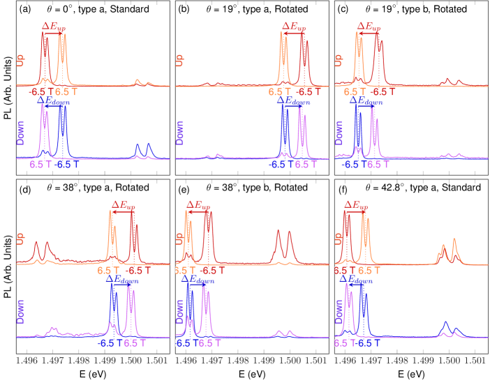
For the angle resolved experiment that tests the magneto-Stark effect, PL spectra were acquired on multiple different SF pyramids positioned at various angles. The spectra of the up and down SF at T are shown in Fig. S9. We note that the PL spectra show a strong and a weak doublet. The origin of the weak doublet is unknown, but we tentatively attribute it to scatter of PL from other exciton populations.
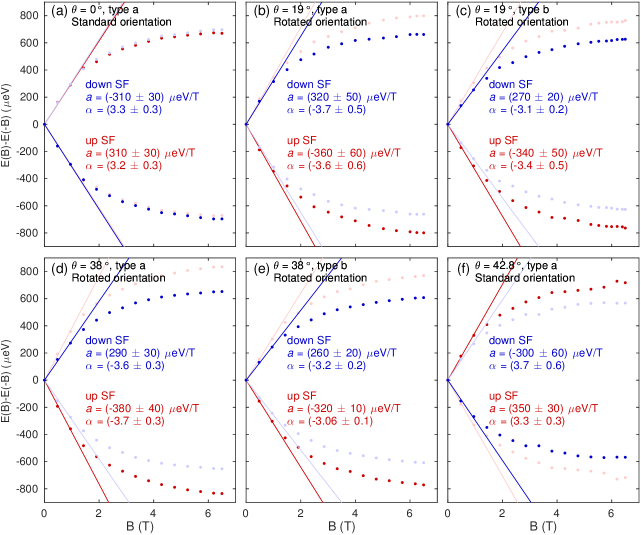
We note that there are two types of SF pyramids: one where the left/right SFs show higher energy PL than the up/down SFs (type a), and a second type where the emission energies are swapped (type b). For example, using this naming scheme the SF pyramid shown in Fig. 1(d) is of type a. Here, the left/right directions refer to the direction of the majority of the intrinsic/extrinsic pair defects, visible as single triangles in Fig. 1(a). We also define a standard and rotated orientation of the bulk crystal depending on whether the sample is mounted as it is in Fig. 1(a) (standard) or rotated by about [001] (rotated).
The PL emission energy as a function of magnetic field for the 6 SFs is shown in Fig. S10. These plots show that , i.e., the electron-hole separation, changes sign for different SF pyramids. The sign of the splitting reflects the direction of the exciton dipole moment along the SF normal. From Fig. S10, we find that the atomic structure of the SF pyramid has a reflection symmetry in the set of planes, i.e. where the up and down SFs are interchanged.
S8 Quantitative interpretation of Angle Resolved Data
Combining Eq. (2) and (3) of the main text and averaging over two spin states of the exciton’s electron, the observed magneto-Stark shift is
| (S15) | ||||
where the light emission angles are related by Snell’s law: , is the angle the SF normal makes with the [001] axis and is the Bohr magneton (CGS units). Here is a dimensionless measure of the dipole moment:
| (S16) |
where is the hole-electron separation in the exciton, and are the hole and electron coordinates and denotes the quantum mechanical average (note CGS units). The numerical value uses the estimated in-plane exciton mass described in Sec. S5. The quantity is the odd part of doubled, which is insensitive to overall offsets and the diamagnetic shift. When , PL from the up and down SFs arises from excitons with the same absolute value of momentum and hence and have the same magnitude [Fig. 3(d)]. When the angle is increased, and have different magnitudes [Fig. 3(e)].
In the linear in regime, the magnetic field is not expected to significantly perturb the exciton dipole moment, and so to first order should be proportional to . Experimentally, we find the energy shift is linear with for , and we extract the proportionality constant using a fit to . The estimate of the dimensionless dipole moment depends somewhat on the fitting method used to find the slope vs. at from the experimental data. Using different methods, we obtain values of ranging from 3.2 to 4.3, and we conservatively use the lowest value of to estimate the exciton dipole moment. Given the uncertainty in the measurement of and the estimation of the in-plane exciton effective mass (Sec. S5), the best guess for the dipole moment is , with the true value estimated to fall between and .
We note that the combination
| (S17) |
depends only on given geometry and the index of refraction (to first order in ), and is independent of the exciton dipole moment. Using Eq. S15 and expanding about small , we can produce a small- approximation for ,
| (S18) |
correct to within 10% for angles up to 45∘ and . We obtain good agreement between calculated experimentally from the slope of with Eq. S17. (Fig. 3h). We emphasize that this model agrees with the data without any fit parameters.
References
- Guha et al. (1993) S. Guha, J. M. DePuydt, M. A. Haase, J. Qiu, and H. Cheng, “Degradation of II-VI based blue-green light emitters,” Applied Physics Letters 63, 3107–3109 (1993).
- Colli et al. (2003) A. Colli, E. Pelucchi, and A. Franciosi, “Controlling the native stacking fault density in II-VI/III-V heterostructures,” Applied Physics Letters 83, 81–83 (2003).
- Caroff et al. (2011) P. Caroff, J. Bolinsson, and J. Johansson, “Crystal phases in III–V nanowires: from random toward engineered polytypism,” IEEE Journal of Selected Topics in Quantum Electronics 17, 829–846 (2011).
- Akopian et al. (2010) N. Akopian, G. Patriarche, L. Liu, J. C. Harmand, and V. Zwiller, “Crystal phase quantum dots,” Nano Lett. 10, 1198–1201 (2010).
- Assali et al. (2013) S. Assali, I. Zardo, S. Plissard, D. Kriegner, M. A. Verheijen, G. Bauer, A. Meijerink, A. Belabbes, F. Bechstedt, J. E. M. Haverkort, and E. P. A. M. Bakkers, “Direct band gap wurtzite gallium phosphide nanowires,” Nano Letters, Nano Lett. 13, 1559–1563 (2013).
- Butov et al. (2002a) L. V. Butov, A. C. Gossard, and D. S. Chemla, “Macroscopically ordered state in an exciton system,” Nature 418, 751–754 (2002a).
- High et al. (2009) A. A. High, A. K. Thomas, G. Grosso, M. Remeika, A. T. Hammack, A. D. Meyertholen, M. M. Fogler, L. V. Butov, M. Hanson, and A. C. Gossard, “Trapping indirect excitons in a GaAs quantum-well structure with a diamond-shaped electrostatic trap,” Phys. Rev. Lett. 103, 087403 (2009).
- Snoke et al. (2002) D. Snoke, S. Denev, Y. Liu, L. Pfeiffer, and K. West, “Long-range transport in excitonic dark states in coupled quantum wells,” Nature 418, 754–757 (2002).
- Butov et al. (2002b) L. V. Butov, C. W. Lai, A. L. Ivanov, A. C. Gossard, and D. S. Chemla, “Towards Bose–Einstein condensation of excitons in potential traps,” Nature 417, 47 (2002b).
- Shilo et al. (2013) Yehiel Shilo, Kobi Cohen, Boris Laikhtman, Ken West, Loren Pfeiffer, and Ronen Rapaport, “Particle correlations and evidence for dark state condensation in a cold dipolar exciton fluid,” Nat Commun 4 (2013), 10.1038/ncomms3335.
- High et al. (2013) A. A. High, A. T. Hammack, J. R. Leonard, Sen Yang, L. V. Butov, T. Ostatnický, M. Vladimirova, A. V. Kavokin, T. C. H. Liew, K. L. Campman, and A. C. Gossard, “Spin currents in a coherent exciton gas,” Physical Review Letters 110 (2013), 10.1103/physrevlett.110.246403.
- Fogler et al. (2014) M. M. Fogler, L. V. Butov, and K. S. Novoselov, “High-temperature superfluidity with indirect excitons in van der Waals heterostructures,” Nature Communications 5 (2014), 10.1038/ncomms5555.
- Gorbunov and Timofeev (2006) A. V. Gorbunov and V. B. Timofeev, “Large-scale coherence of the bose condensate of spatially indirect excitons,” JETP Letters 84, 329 (2006).
- Snoke (2011) D. W. Snoke, “Coherence and optical emission from bilayer exciton condensates,” Advances in Condensed Matter Physics 2011, 1–7 (2011).
- Nelsen et al. (2009) B. Nelsen, R. Balili, D. W. Snoke, L. Pfeiffer, and K. West, “Lasing and polariton condensation: Two distinct transitions in GaAs microcavities with stress traps,” Journal of Applied Physics 105, 122414 (2009).
- Balili et al. (2009) R. Balili, B. Nelsen, D. W. Snoke, L. Pfeiffer, and K. West, “Role of the stress trap in the polariton quasiequilibrium condensation in GaAs microcavities,” Phys. Rev. B 79, 075319 (2009).
- High et al. (2012) A. A. High, J. R. Leonard, A. T. Hammack, M. M. Fogler, L. V. Butov, A. V. Kavokin, K. L. Campman, and A. C. Gossard, “Spontaneous coherence in a cold exciton gas,” Nature 483, 584–588 (2012).
- Amo et al. (2010) A. Amo, T. C. H. Liew, C. Adrados, R. Houdre, E. Giacobino, A. V. Kavokin, and A. Bramati, “Exciton-polariton spin switches,” Nature Photonics 4, 361–366 (2010).
- Nguyen et al. (2013) H. S. Nguyen, D. Vishnevsky, C. Sturm, D. Tanese, D. Solnyshkov, E. Galopin, A. Lemaître, I. Sagnes, A. Amo, G. Malpuech, and J. Bloch, “Realization of a double-barrier resonant tunneling diode for cavity polaritons,” Phys. Rev. Lett. 110, 236601 (2013).
- Kammann et al. (2012) E. Kammann, T. C. H. Liew, H. Ohadi, P. Cilibrizzi, P. Tsotsis, Z. Hatzopoulos, P. G. Savvidis, A. V. Kavokin, and P. G. Lagoudakis, “Nonlinear optical spin Hall effect and long-range spin transport in polariton lasers,” Phys. Rev. Lett. 109, 036404 (2012).
- (21) See Supplemental Material at [URL will be inserted by publisher] for details on sample growth, an overview of the optical spectroscopy system, details of the linewidth measurements, data for the angle resolved experiment, derivation of the magneto-Stark Hamiltonian and an explanation of the -factor analysis.
- Kasai and Kawata (1998) J. Kasai and M. Kawata, “Microphotoluminescence of oval defects in a GaAs layer grown by molecular beam epitaxy,” Applied Physics Letters 73, 2012–2014 (1998).
- Lähnemann et al. (2014) J. Lähnemann, U. Jahn, O. Brandt, T. Flissikowski, P. Dogan, and H. T. Grahn, “Luminescence associated with stacking faults in GaN,” Journal of Physics D: Applied Physics 47, 423001 (2014).
- Algra et al. (2008) R. E. Algra, M. A. Verheijen, M. T. Borgstrom, L. F. Feiner, G. Immink, W. J. P. van Enckevort, E. Vlieg, and E. P. A. M. Bakkers, “Twinning superlattices in indium phosphide nanowires,” Nature 456, 369–372 (2008).
- Belabbes et al. (2012) A. Belabbes, C. Panse, J. Furthmüller, and F. Bechstedt, “Electronic bands of III-V semiconductor polytypes and their alignment,” Phys. Rev. B 86, 075208 (2012).
- Spirkoska et al. (2009) D. Spirkoska, J. Arbiol, A. Gustafsson, S. Conesa-Boj, F. Glas, I. Zardo, M. Heigoldt, M. H. Gass, A. L. Bleloch, S. Estrade, M. Kaniber, J. Rossler, F. Peiro, J. R. Morante, G. Abstreiter, L. Samuelson, and Fontcuberta, “Structural and optical properties of high quality zinc-blende/wurtzite GaAs nanowire heterostructures,” Phys. Rev. B 80, 245325 (2009).
- Heiss et al. (2011) M. Heiss, S. Conesa-Boj, J. Ren, H. H. Tseng, A. Gali, A. Rudolph, E. Uccelli, F. Peiró, J. R. Morante, D. Schuh, E. Reiger, E. Kaxiras, J. Arbiol, and Fontcuberta, “Direct correlation of crystal structure and optical properties in wurtzite/zinc-blende GaAs nanowire heterostructures,” Phys. Rev. B 83, 045303 (2011).
- Lähnemann et al. (2012) J. Lähnemann, O. Brandt, U. Jahn, C. Pfüller, C. Roder, P. Dogan, F. Grosse, A. Belabbes, F. Bechstedt, A. Trampert, and L. Geelhaar, “Direct experimental determination of the spontaneous polarization of GaN,” Phys. Rev. B 86, 081302 (2012).
- Vainorius et al. (2015) N. Vainorius, S. Lehmann, D. Jacobsson, L. Samuelson, K. A. Dick, and M. E. Pistol, “Confinement in thickness-controlled GaAs polytype nanodots,” Nano Lett. 15, 2652–2656 (2015).
- Fung et al. (1997) K. K. Fung, N. Wang, and I. K. Sou, “Direct observation of stacking fault tetrahedra in ZnSe/GaAs(001) pseudomorphic epilayers by weak beam dark-field transmission electron microscopy,” Applied Physics Letters 71, 1225–1227 (1997).
- Wang et al. (2000) N. Wang, K. K. Fung, and I. K. Sou, “Direct observation of stacking fault nucleation in the early stage of ZnSe/GaAs pseudomorphic epitaxial layer growth,” Applied Physics Letters 77, 2846–2848 (2000).
- Corfdir and Lefebvre (2012) P. Corfdir and P. Lefebvre, “Importance of excitonic effects and the question of internal electric fields in stacking faults and crystal phase quantum discs: The model-case of GaN,” Journal of Applied Physics 112, 053512 (2012).
- Kakibayashi et al. (1984) H. Kakibayashi, F. Nagata, Y. Katayama, and Y. Shiraki, “Structure analysis of oval defect on molecular beam epitaxial GaAs layer by cross-sectional transmission electron microscopy observation,” Japanese Journal of Applied Physics 23, L846–L848 (1984).
- Komatsu (1988) Teruo Komatsu, “Optical properties of excitons confined two-dimensionally in a stacking fault plane in BiI3,” Journal of Luminescence 40-41, 495–496 (1988).
- Poltavtsev et al. (2014) S. V. Poltavtsev, Yu Efimov, Yu Dolgikh, S. A. Eliseev, V. V. Petrov, and V. V. Ovsyankin, “Extremely low inhomogeneous broadening of exciton lines in shallow (In,Ga)As/GaAs quantum wells,” Solid State Communications 199, 47–51 (2014).
- Graham et al. (2013) A. M. Graham, P. Corfdir, M. Heiss, S. Conesa-Boj, E. Uccelli, Fontcuberta, and R. T. Phillips, “Exciton localization mechanisms in wurtzite/zinc-blende GaAs nanowires,” Phys. Rev. B 87, 125304 (2013).
- Pal et al. (2008) B. Pal, K. Goto, M. Ikezawa, Y. Masumoto, P. Mohan, J. Motohisa, and T. Fukui, “Type-II behavior in wurtzite InP/InAs/InP core-multishell nanowires,” Applied Physics Letters 93, 073105 (2008).
- Signorello et al. (2014) G. Signorello, E. Lörtscher, P. A. Khomyakov, S. Karg, D. L. Dheeraj, B. Gotsmann, H. Weman, and H. Riel, “Inducing a direct-to-pseudodirect bandgap transition in wurtzite GaAs nanowires with uniaxial stress,” Nature Communications 5 (2014), 10.1038/ncomms4655.
- Spirkoska et al. (2012) D. Spirkoska, A. L. Efros, W. R. L. Lambrecht, T. Cheiwchanchamnangij, A. F. Morral, and G. Abstreiter, “Valence band structure of polytypic zinc-blende/wurtzite GaAs nanowires probed by polarization-dependent photoluminescence,” Phys. Rev. B 85, 045309 (2012).
- Note (1) Our sample is non-magnetic and we use linearly polarized light to avoid dynamic polarization of nuclear spins.
- Knox (1963) R. S. Knox, Theory of Excitons - Supplement 5 Solid State Physics (Academic Press, New York, New York, 1963).
- Note (2) Experimentally, the objective lens collects luminescence from a range of angles. In our system, light is collected from excitons momenta within 7% of in Eq. (2\@@italiccorr).
- Gross et al. (1961) E. F. Gross, B. P. Zakharchenya, and O. V. Konstantinov, “Effect of magnetic field inversion in spectra of exciton absorption in CdSe crystal,” Sov. Phys. Solid State 3, 221 (1961).
- Thomas and Hopfield (1961) D. G. Thomas and J. J. Hopfield, “A magneto-Stark effect and exciton motion in CdS,” Phys. Rev. 124, 657–665 (1961).
- Jahn et al. (2012) U. Jahn, J. Lähnemann, C. Pfüller, O. Brandt, S. Breuer, B. Jenichen, M. Ramsteiner, L. Geelhaar, and H. Riechert, “Luminescence of GaAs nanowires consisting of wurtzite and zinc-blende segments,” Physical Review B 85 (2012), 10.1103/physrevb.85.045323.
- Warburton et al. (2002) R. J. Warburton, C. Schulhauser, D. Haft, C. Schäflein, K. Karrai, J. M. Garcia, W. Schoenfeld, and P. M. Petroff, “Giant permanent dipole moments of excitons in semiconductor nanostructures,” Phys. Rev. B 65, 113303 (2002).
- Chai et al. (1985) Y. G. Chai, Y-c, and T. Hierl, “Elimination of “pair” defects from GaAs layers grown by molecular beam epitaxy,” Applied Physics Letters 47, 1327–1329 (1985).
- Haverkort et al. (1992) J. E. M. Haverkort, M. P. Schuwer, M. R. Leys, and J. H. Wolter, “Spatial variations of photoluminescence line broadening around oval defects in GaAs/AlGaAs multiple quantum wells,” Semiconductor Science and Technology 7 (1992).
- Bir and Pikus (1974) G. L. Bir and G. E. Pikus, Symmetry and strain-induced effects in semiconductors (Halsted Press, 1974).
- Koster et al. (1963) G. F. Koster, J. O. Dimmock, and R. G. Wheeler, Properties of the thirty-two point groups (M.I.T. Press, 1963).
- Dresselhaus et al. (2008) M. S. Dresselhaus, G. Dresselhaus, and A. Jorio, Group Theory: Application to the Physics of Condensed Matter, 2008th ed. (Springer, Berlin, Germany, 2008).
- Birman (1959) J. L. Birman, “Some selection rules for band-band transitions in wurtzite structure,” Phys. Rev. 114, 1490–1492 (1959).
- Dresselhaus (1955) G. Dresselhaus, “Spin-orbit coupling effects in zinc blende structures,” Phys. Rev. 100, 580–586 (1955).
- Herring (1937) C. Herring, “Effect of time-reversal symmetry on energy bands of crystals,” Phys. Rev. 52, 361–365 (1937).
- Elliott (1954) R. J. Elliott, “Spin-orbit coupling in band theory–character tables for some “double” space groups,” Phys. Rev. 96, 280–287 (1954).
- Sallen et al. (2011) G. Sallen, B. Urbaszek, M. M. Glazov, E. L. Ivchenko, T. Kuroda, T. Mano, S. Kunz, M. Abbarchi, K. Sakoda, D. Lagarde, A. Balocchi, X. Marie, and T. Amand, “Dark-bright mixing of interband transitions in symmetric semiconductor quantum dots,” Phys. Rev. Lett. 107, 166604 (2011).
- Burns (1977) G. Burns, Introduction to group theory with applications: materials science and technology (Academic Press, 1977).
- Ivchenko and Pikus (1997) E. L. Ivchenko and G. E. Pikus, Superlattices and other heterostructures: symmetry and optical phenomena (Springer, 1997).
- Ikonic´ et al. (1992) Z. Ikonic´, V. Milanovic´, and D. Tjapkin, “Valence subband structure of [100]-, [110]-, and [111]-grown GaAs-(Al,Ga)As quantum wells and the accuracy of the axial approximation,” Physical Review B 46, 4285–4288 (1992).