Follow, listen, feel and go:
alternative guidance systems for
a walking assistance device
Abstract
In this paper, we propose several solutions to guide an older adult along a safe path using a robotic walking assistant (the c-Walker). We consider four different possibilities to execute the task. One of them is mechanical, with the c-Walker playing an active role in setting the course. The other ones are based on tactile or acoustic stimuli, and suggest a direction of motion that the user is supposed to take on her own will.
We describe the technological basis for the hardware components implementing the different solutions, and show specialised path following algorithms for each of them.
The paper reports an extensive user validation activity with a quantitative and qualitative analysis of the different solutions. In this work, we test our system just with young participants to establish a safer methodology that will be used in future studies performed with older adults.
1 Introduction
Ageing is often associated with reduced mobility which is the consequence of a combination of physical, sensory and cognitive degrading. Reduced mobility may weaken older adults’ confidence in getting out alone and traveling autonomously in large spaces. Reduced mobility has several serious consequences including an increase in the probability of falls and other physical problems, such as diabetes or articular diseases. Staying at home, people lose essential opportunities for socialisation and may worsen the quality of their nutrition. The result is a self-reinforcing loop that exacerbates the problems of ageing and accelerates physical and cognitive decline Cacioppo2009 .
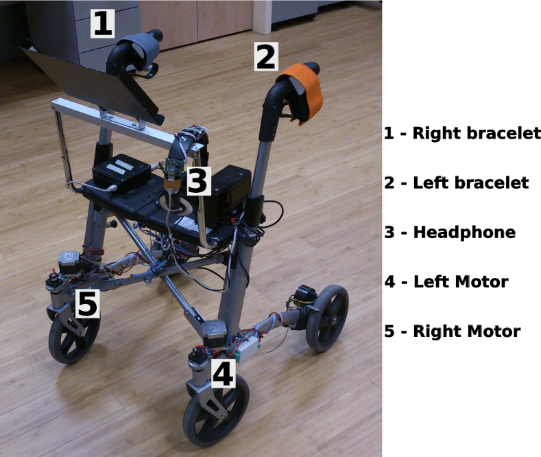
In the context of different research initiatives (the DALi project111http://www.ict-dali.eu and the ACANTO project222http://www.ict-acanto.eu) we have developed a robotic walking assistant, that compensates for sensory and cognitive impairments and supports the user’s navigation across complex spaces. The device, called c-Walker (Fig. 1), is equipped with different types of low level sensors (encoders, inertial measurement unit) and advanced sensors (cameras) that collect information on the device and its environment. Such measurements are used by the c-Walker to localise itself and to detect potential risks in the surrounding environment. By using this information the c-Walker is able to produce a motion plan that prevents accidents and drives the user to her destination with a small effort and satisfying her preferences. The projects follow an inclusive design approach which requires older users involvement and participation at appropriate moments in the process once the evaluation protocols have been validated.
There are different interfaces that the c-Walker can use to guide the user. Some of them generate acoustic and tactile stimulation to suggest the correct direction of motion. The user remains in charge of the last decision on whether to accept or refuse the suggestions. A different type of mechanisms operates “actively” on the walker, by physically changing the direction of motion.
In this work we describe four different mechanisms for guidance available in the c-Walker (mechanical, haptic, and two types of acoustic guidance) showing how they can be applied in the context of a guidance algorithm and their effect on a student population. The mechanical guidance is based on the action of two stepper motors that can change the orientation of the front wheels forcing a turn in the desired direction. The haptic guidance is a passive system based on the use of a pair of bracelets that vibrate in the direction the user is suggested to take. The same effect can be obtained by administering acoustic signals to the user through a headphone: a sound on the right side to suggest a right turn, and a sound on the left side to suggest a left turn. The acoustic medium has a richer potential. Indeed, by using appropriate algorithms, it is possible to simulate a sound in the space that the user should follow in order to move in the right direction.
In the paper, we describe the theoretical foundations of the different mechanisms and algorithms and offer some details and insight on how they can be integrated in the c-Walker. In addition, we present the results of two evaluation studies aimed at providing a protocol for the evaluation of the performance of the guidance systems and initial knowledge on user behavior and experience. Results suggest that the mechanical performance is the best and expose strengths and weaknesses of the other solutions, opening important design directions for future guidance systems design.
The paper is organised as follows. In Sec. 2, we review the most important scientific literature related to our work. In Sec. 3, we describe the hardware and software components of the system, while in Sec. 4, we illustrate the different guidance mechanisms used in the c-Walker. In Sec. 5, we describe the guidance algorithms of the different guidance mechanisms. We report our testing and validation activities performed with young participants on all of the systems in Sec. 6, and finally we conclude with Sec. 7.
2 Related Work
The robot wheelchair proposed in urdiales2011new offers guidance assistance in such a way that decisions come from the contribution of both the user and the machine. The shared control, instead of a conventional switch from robot to user mode, is a collaborative control. For each situation, the commands from robot and user are weighted according to the respective experience and ability leading to a combined action.
Other projects make use of walkers to provide the user with services such as physical support and obstacle avoidance. In chuy2006new , the walker can work in manual mode where the control of the robot is left to the user and only voice messages are used to provide instructions. A shared control operates in automatic mode when obstacle avoidance is needed and user intention is overridden acting on the front wheels.
The two projects just mentioned can be considered as “active” guidance systems, meaning that the system actively operates to steer the user toward the desired direction. The c-Walker’s mechanical guidance considered in this paper falls in the same category. Another point of commonality is in the strict cooperation between the system that generates suggestions and the user that has to implement these decisions. In the c-Walker, the user comfort has the same importance as the accuracy and efficiency of the guidance solution. In fact, not only does the user provides motive power but she can also decide to override the system’s decisions forcing her way out of the suggested path.
Key to any guidance system of this kind is the ability to detect and possibly anticipate the user’s intent. A valuable help in this direction can be offered by the use of force sensors. wasson2003user use force sensors to modify the orientation of the front wheels of a walker in case of concerns about comfort and safety of the user motion. In chuy2007control an omnidirectional mobile base makes possible to change the centre of rotation to accommodate user intended motion. Contrary to these projects, the c-Walker is intended as a low cost system, for which expensive force sensors are not affordable. The user intent is inferred indirectly by observing gait, and by estimating her emotional state.
More similar to our ideas, is the JAIST active robotic walker (JaRoW), proposed by lee2010design , which uses infrared sensors to detect lower limb movement of the user and adapt direction and velocity to her behaviour.
A possible idea to reduce intrusivenenss is to use passive devices, where suggestions on the direction of motion take the form of visual, auditory or tactile stimuli, and the user remains totally in charge of the final decision. Haptic interfaces can be used as a practical method to implement this idea. Successful stories on the use of haptic interface can be found in the area of teleoperation of vehicles for surveillance or exploration of remote or dangerous areas. For this type of applications, haptic interfaces are used to provide feedback on sense of motion and the feeling of presence, as in Arias2010 . Similar requirements can be found in rescue activities, where the robot helps the user to move in environments where visual feedback are no longer available (ghosh2014following ). In the latter application the robot provides information on its position and direction to the user in order to help the user follow the robot. Guidance assistance can be provided by giving feedback on the matching between the trajectory followed by the user and the planned trajectory. In ScMoPr-TH14 , a bracelet provides a warning signal when a large deviation with respect to the planned trajectory is detected. In ErVeJaDo2005 a belt with eight tactors is used to provide direction information to the user in order to complete a way-point navigation plan. As shown below, haptic bracelets are one possible guidance method offered by the c-Walker.
Another “passive” guidance system is based on acoustic signalling and is well–suited to users with partial or total visual disabilities. Acoustic guidance can be achieved by synthesising a sound from a virtual point in the direction the user should move toward. A key element of this method is the ability to efficiently and accurately render sound signals from a specified point. The main method to achieve this is based on the Head Related Transfer Function (HRTF) which changes and needs to be determined for each individual, as explained in blauert . It represents the ears response for a given direction of the incoming sound. Other approaches are based on the modelling of the sound propagation. In the modelling process, attenuation of the sound is taken into account using the Interaural Level Difference (ILD) which considers the presence of the listener head. Instead, Interaural Time Difference (ITD) considers the distance between ears and sound source. These filtering processes are computationally demanding. The acoustic guidance mechanism implemented in the c-Walker is based on the adoption of lightweight algorithms amenable to an embedded implementation and detailed in rizzon2013embedded ; rizzon2014spatial .
3 System architecture
The c-Walker hardware and software architecture has been designed for an easy integration of heterogeneous components (possibly developed by different teams).
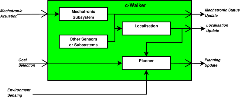
The core modules of the architecture are shown in Figure 2. The Planner decides the plan to be followed based on: 1. the requests and the preferences of the user, 2. the map of the environment, 3. the presence of obstacles and crowded areas along the way. While the c-Walker is moving, it collects information from the environment and the planned path can be updated to avoid obstacles or safety risks colombo2013motion .
The Localisation module integrates information from several sources (encoders, Inertial platform, cameras, RFID reader) to produce an updated information on the estimated position of the vehicle in the environment with a few centimetres position Naz14 . A mechatronic subsystem encapsulates all the modules that are used to read and process sensor data from the encoders and from the inertial sensors. Additionally, the mechatronic module contains all the logic required to send command to the actuators (e.g., the motors on the caster wheels). The mechatronic system is reached through a CAN bus.
These core modules can be interconnected with other modules to implement the different guidance solutions discussed above, as shown in Fig. 2.
The different components are interconnected using a publisher/subscriber middleware, whereby a component can publish messages that are broadcast through all the diffferent level of networking (CAN bus for mechatronic components, ethernet for high level sensors and computing nodes) in the c-Walker. This is a key enabler for the adoption of a truly component–based paradigm, in which the different guidance systems can be obtained by simply tuning on some of the modules and allowing them to publish messages or subscribe to messages. Three different configurations are schematically shown in Fig. 3.
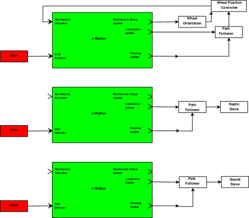
Fig. 3 shows how the three guidance systems that we present in this work interact with c-Walker. The scheme on the top of the figure refers to mechanical guidance. The Planner periodically publishes updated plans (i.e., the coordinates of the next points to reach). This information subscribed to by a path follower that implements the algorithm presented in Section 5.2. This component decides a direction for the wheel that is transmitted to a Wheel Position Controller using the Publish/Subscribe middleware. This component also receives real–time information on the current orientation of the wheel and decides the actuation to set the direction to the desired position. The schemes on the middle and on the bottom apply, respectively, to haptic and acoustic (and binaural) guidance. In this case the Path Follower Components implements the algorithms discussed in Section 5.1 and transmits its input either the Haptic Slave (see Section 4.1) or the the Audio Slave (see Section 4.2).
4 Guidance mechanisms
In this section, we describe the three main mechanisms that can be used as “actuators” to suggest or to force changes in the direction of motion.
4.1 Bracelets
Haptic guidance is implemented through a tactile stimulation that takes the form of a vibration. A device able to transmit haptic signals through vibrations is said “vibrotactile”.
Vibration is best transmitted on hairy skin because of skin thickness and nerve depth, and it is best detected in bony areas. Wrists and spine are generally the preferred choice for detecting vibrations, with arms immediately following. Our application is particularly challenging for two reasons: I. the interface is designed to be used by older adults, II. the signal is transmitted while the user moves. Movement is known to affect adversely the detection rate and the response time of lower body sites (Karuei-2011 ). As regards the perception of tactile stimuli by older adults, gescheider94 present studies on the effects of aging in the sense of touch, which revealed that detection thresholds for several vibration intensities are higher in older subjects in the age class .
Bearing in mind these facts, we designed a wearable haptic bracelet in which two cylindrical vibro–motors generate vibratory signals to warn the user (Fig. 1). The subject wears one vibrotactile bracelet on each arm in order to maximize the stimuli separation while keeping the discrimination process as intuitive as possible. In particular, vibration of the left wristband suggests the participant to turn left, and vice versa.
On each bracelet the distance between the two motors is about mm. In two-point discrimination, the minimal distance between two stimuli to be differentiated is about mm on the forearms and there is no evidence for differences among the left and right sides of the body, according to Weinstein68 . In order to reduce the aftereffect problem typical of continuous stimuli and to preserve users’ ability to localize vibration, we selected a pulsed vibrational signal with frequency Hz and amplitude of g, instead of a continuous one. In particular, when a bracelet is engaged its two vibrating motors alternatively vibrates for s. The choice of using two vibrating motors instead of one was the effect of a pilot study in which a group of older adults tested both options and declared their preference for the choice of two motors. The choice of frequency and amplitude of the vibrations was another outcome of this study (see ScAgPr-IMEKO14 ).
From the technological point of view, two Precision Microdrives Pico Vibe mm vibration motors were placed into two fabric pockets on the external surface of the bracelet (the width of the wristband is about mm), with shafts aligned with the elbow bone. The motors have a vibration frequency range of Hz - Hz (the maximal sensitivity is achieved around Hz - Hz), lag time of ms, rise time of ms and stop time of ms.
4.2 Audio interface
The acoustic interface communicates to the user the direction to take by transmitting synthetic signals through a headphone (Fig. 1). For instance, when the system aims to suggest a left turn to the user, it reproduces a sound that is perceived by the user as coming from a point on her left aligned with the direction she is supposed to take. This is possible thanks to the application of the binaural theory.
The software module that generates this sound is called Audio Slave and it receives from a master the spatial coordinates of the point that is required to be the source of the sound. The audio slave converts the cartesian coordinates into a pair of relative polar coordinates, in which represent the distance between the virtual sound source and the centre of the listener’s head, and represent the azimuthal angle. The pair univocally identifies the position of the sound source on the horizontal plane. takes on the value when the source is in front of the user, positive angles identify positions on the right hand side, and negative values of identify positions on the left of the listener. The guidance signal is a white noise with duration ms, which is repeated every ms. The binaural processing algorithm has been used to implement two different versions of the guidance interface:
-
•
Left/Right Guidance;
-
•
Binaural Guidance.
Using the Left/Right Guidance Interface, the system reproduces only virtual sources placed at or at to suggest a right turn or a left turn, in the same way as the haptic interface. With the Binaural Guidance Interface, a virtual sound source is allowed to be in any position. The resulting suggestion is not merely for a turn, but it specifies a finer grained information on the exact direction. In this case, to ensure the correct displacement of the virtual sound relative to the user head orientation, an Inertial Measurement Unit (IMU) monitors the listener’s head position with respect to the c-Walker.
Both the interface implementations are based on the same sound rendering engine which is based on the physics of sound waves. Each of the sound samples is delayed, and attenuated according to the principles of sound wave propagation. The binaural effect is obtained by proper filters that reproduce the presence of the listener’s head and consider the ears displacement. However, the guidance interface is meant to generate recommendations on the direction to follow; therefore, stimuli have been processed without reverberation. As a consequence, users will perceive the sounds as intracranial, since the absence of reverb makes it difficult to externalize virtual sound stimuli.
4.3 Mechanical Steering
The mechanical system based on steering uses the front caster wheels to suggest the user which direction to follow. The positioning of the wheels causes the c-Walker to perform a smooth turn manoeuvre without any particular intervention from the user and therefore is considered as an active guidance. That is, the user provides only the necessary energy to push the vehicle forward. Other active approaches exploiting the braking system acting on the back wheels of the walker have been presented recently in the literature, among which FontanelliGPP13 ; saida2011development . However, the front wheels steering approach is more robust and less demanding, in terms of processing power and sensor measures requests and was then adopted for this paper.
More in depth, the c-Walker is endowed with two caster wheels in front of the device, which are connected to a swivel that enables them to move freely around their axis. Taking advantage of this feature, we applied steppers motors to the joints to change the direction of the wheels by a specified amount. The presence of non-idealities (e.g., friction and slippage of the gears) can possibly introduce a deviation between the desired rotation angle and the actual one. Therefore, we need a position control scheme operating with real–time measurements of the current angular position of the wheels. Such measurements are collected by an encoder that is mounted on the same joint as the stepper motor. The connection between wheel and motor is through a gear system such that a complete turn of the wheel is associated with 4 turns of the motor. Every complete turn of the motor is steps. The stepper motor and the encoder are controlled by a small computing node that is interfaced to the rest of the system through a CAN bus. The motor, together with the absolute encoder and the relative CAN bus node, is visible in Fig. 1.
With a fixed periodicity, the node samples the encoder and broadcasts the sensor reading through the bus. The node can also receive a CAN message coming from other computing devices that requires a rotation of the wheels specifying the number of degree of rotation and the angular velocity (deg/s). The values are automatically converted in steps and used in a PID control loop that moves the wheel to the specified angular position.
5 Guidance algorithms
The guidance algorithms relies on an accurate estimate of the position of the c-Walker with respect to the planned path. Since the latter is generated internally by a module of the c-Walker (see ColomboFLPS13 ), only the knowledge on the position and of the orientation expressed in some known reference frame is needed. This problem, known in the literature as localisation problem, is solved in the c-Walker using the solutions proposed in NazemzadehFM13 ; NazemzadehFMP14 .
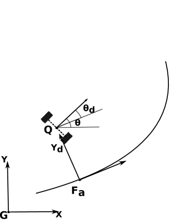
With this information it is possible to determine the Frenet-Serret point , that is a point on the path representing the intersection between the projection of the vehicle and a segment that is perpendicular to it and tangent to the path, as in Fig. 4 (a).
 |
 |
| (a) | (b) |
We define as and respectively the distance along the projection of the vehicle to and the difference between the orientation of the c-Walker and the orientation of the tangent to the path in the projection point. All the proposed guidance algorithms use this information to compute the specific “actuation”.
We observe that the objective of the guidance algorithms is not the perfect path following of the planned trajectory. In fact, such an objective would be very restrictive for the user and perceived as too authoritative and intrusive. In order to give the user the feeling of being in control of the platform, she is allowed an error (in both, position and orientation) throughout the execution of the path that is kept lower than a desired performance threshold. Therefore, the path can be considered as the centre line of a virtual corridor in which the user can move freely.
5.1 Haptic and Acoustic algorithms
The haptic and acoustic guidance algorithms generate a quantised control action, which can be described with an alphabet of three control symbols: a) turn right; b) turn left; c) go straight. This is a good compromise between accuracy and cognitive load for the interpretation of signals.
The symbol to be suggested to the user is determined by the desired turning towards the path. A straightforward way to compute such a quantity is to determine the angular velocity an autonomous robotic unicycle–like vehicle would follow in order to solve the path following problem. To this end, we have designed a very simple control Lyapunov function which ensures a controlled solution to the path following in the case of straight lines acting only on the vehicle angular velocity and irrespective of the forward velocity of the vehicle. Such a controller works also for curved paths if we are only interested on the sign of the desired angular velocity.
To see this, consider the kinematic model of the unicycle (which is an accurate kinematic model of the c-Walker)
| (1) | ||||
where is the forward velocity and its angular velocity. and are the quantities defined in the previous section, while is the longitudinal coordinate of the vehicle that, in the Frenet-Serret reference frame is identically zero by definition. It has to be noted that are then the cartesian coordinates, in the Frenet-Serret reference frame, of the midpoint of the rear wheels axle. In light of model (1) and remembering that does not play any role for path following, we can set up the following control Lyapunov function
| (2) |
which is positive definite in the space of interest, i.e., , and has as time derivative
| (3) |
where and are tuning constants. Imposing equals to the following desired angular velocity
| (4) |
with additional degree of freedom, the time derivative in (3) is negative semidefinite; using La Salle and Krasowskii principles, asymptotic stability of the equilibrium point can therefore be established, with the c-Walker steadily moving toward the path.
As a consequence, the sign of rules the direction of switching: a) if then the user has to turn left; b) if then the user has to turn right; c) if then the user has to go straight. is a design threshold used to be traded between the user comfort and the authority of the control action.
In order to implement the idea of the virtual corridor around the path and to increase the user comfort, the actuation takes place only when in (2) is greater than a certain , which is defined as in (2) when is half the width of the corridor, and defines half of the amplitude of a cone centered on the corridor orientation in which the c-Walker heading is allowed. For the haptic, acoustic algorithms the parameters that define the corridor are the same, that are m and rad. Similarly, the constants , and are fixed to the same values for both haptic guidance and acoustic guidance. However, they are changing according to the c-Walker actual position: when the position is outside the corridor, and , so that the controller is more active to steer the vehicle inside the corridor; when, instead, the c-Walker is within the corridor boundaries, and in order to highly enforce the current orientation tangent to the path. The position of the c-Walker inside the corridor is determined by simply checking if .
Finally, to take into account the corridor, the , where is a time varying parameter related to the corridor, i.e.,
| (5) |
The turning rule related to the sign of is then applied as previously described.
5.1.1 Acoustic source computation
For the acoustic guidance system, the sound source position has to be properly identified. To this end, let us define the circle centered in the vehicle position and having radius ( in the experiments). Let us further define as the segment joining the origin of the Frenet-Serret reference frame with the intersection point between the circle and the tangent to the circle in the origin of . If multiple solutions exist, the one being in the forward direction of the walker is considered. If only a solution exists, i.e., , then coincides with the origin of . Finally, no solution exists if , therefore lies on the segment that connects to .
We define as the point closer to and lying on the path. If the c-Walker is close to a straight component of the path or at a distance greater than , . Otherwise, is computed as the projection of on the path. is the desired sound source with respect to a fixed reference frame, which has to be transformed in the c-Walker reference coordinate systems by
With the choice just illustrated, if the distance from the path is greater than , the target is pushed to the planned path following the shortest possible route.
5.1.2 Actuation
Haptic: The bracelets are actuated according to the direction to follow. There are two choices of actuation: the first considers the value of as discussed above, while the second considers the value of as computed in Sec. 5.1.1. In both cases, the sign determines the direction of turning.
Left/Right Three cones, having the vertices in , are defined: , and . The cones divide the semicircle in front of the vehicle and with center in in three equal sectors. If , the user has to turn left; if , the user has to turn right; if , the user has to go straight. Positions behind the user are transformed in turn left or right depending on the position of . Using this taxonomy and the value of in (5), the slave application determines whether the sound has to be played or not and from which position.
Binaural The binaural algorithm fully exploits the reference coordinates using a finer granularity of positions then the Left/Right acoustic guidance. The number of cones is now equal to 7, with three equally spaced cones on the right and on the left the forward direction of the trolley. Each cone has a characteristic angle , that is the one that equally splits the cone from the cart perspective. The described mechanism has the role of discretising the possible sound directions, since the human auditory system does not have the sensibility to distinguish a finer partition. Again, positions behind the user are treated as in the Left/Right approach in order to avoid front/back confusion that commonly affects binaural sound recognition. As a result of this quantisation, the new position of the sound source is . By defining with the user’s head orientation measured with the IMU placed on top of the headphone, the final sound source is computed as
5.2 Mechanical system: steering
The rationale of the steering wheels controller is in the nature of the kinematic model. With respect to the model adopted in (1), which represents a unicycle-like vehicle model with differential drive on the back wheels, controlling the c-Walker using the steering wheels implies a different dynamic for the orientation rate, that becomes
| (6) |
where is the steering angle. Since the steering angle is generated through the actuation of the front caster wheels, it is directly controlled in position by means of the stepper motors. Moreover, and, hence, there is no theoretical limit on the value of . Nonetheless, there exists a singular point when , which can be ruled out because in such a case the path following does not have any sense even for the model in (1). This condition implies that acting on the steering wheels do not allow a turn on the spot.
As a consequence, it is possible to select any feasible path following controller conceived for the unicycle to solve the problem at hand. The controller adopted is the one proposed by SoetantoLP2003 , which is flexible (indeed, there are tuning parameters for the approaching angle to the path), and can be extended to include dynamic effects and uncertain parameters. The adopted controller, which is an extension of the one presented in micaelli1993trajectory , is based on the idea of a virtual target travelling on the path. Its adaptation to our context is discussed below.
Let be the coordinates of the Virtual vehicle. The objective is to make the c-Walker perfectly track the Virtual vehicle. The position of the walker Q can be expressed in a global frame G with . Alternatively, the point can be expressed in the frame V, which coincides with the point , with .
Expressing with the orientation in the global frame of the tangent to the path in , with the curvilinear abscissa of along the path, and with the curvature of the path in that point, we have . It is now possible to express the new kinematic equations of the c-Walker w.r.t. the new frame starting from (1). Indeed, starting from the rotation matrix relating G to V, i.e.,
we first derive the velocity of the c-Walker:
and, then, we can express them as
| (7) |
where . Using Lyapunov techniques, it is possible to define the following set of control laws (see SoetantoLP2003 for further details)
where represents the progression of the Virtual vehicle on the path, is the angle of approach of the vehicle with respect to the path (that can be tuned as necessary), while the are tuning constants. With this choice, is the angular velocity reference of the c-Walker, which can be generated by solving with respect to the equation (6).
It has to be noted that is the reference of the wheel if the half-car model is adopted. In order to transform the reference to a reference for the left and right wheel, the constraint imposed by the Ackerman geometry are imposed. Finally, in order to implement the idea of the corridor previously presented, the actual steering angle imposed to the wheels considers the reference computed as described in this section as a reference , which is used in combination with the actual orientation . More precisely, using the value of in (5), the commanded orientation of the steering wheel is given by . The value of the threshold in this case is increased to rad.
6 Experimental results
6.1 Study 1
A formative evaluation was designed to compare and contrast the performance of the different guidance systems. Since the preliminary state of user research in this field wilkinson2014demonstrating ; wilkinson2014applying , the main focus of the evaluation was on system performance, rather than on the user experience. The study had two concurrent objectives: to develop a controlled experimental methodology to support system comparisons and to provide practical information to re-design. In this way, future development will provide a tested methodology to preserve elderly participants from stress and fatigue. In line with an ethical application of the inclusive design process keates2003countering , at this early stage of the methodological verification process of an evaluation protocol, we involved a sample of young participants.
6.1.1 Participants
Thirteen participants (6 females, mean age 30 years old, ranging from 26 to 39) took part in the evaluation. They were all students or employees of the University of Trento and gave informed consent prior to inclusion in the study.
6.1.2 Design
The study applied a within-subjects design with Guidance (4) and Path (3) as experimental factors. All participants used the four guidance systems (acoustic, haptic, mechanical, binaural) in three different paths. The order of the system conditions was counterbalanced across participants.
6.1.3 Apparatus
The experimental apparatus used in the experiment is a prototype of the c-Walker shown in Figure 1. An exaustive description of the device and of its different functionalities can be found in pal15 . A distinctive mark of the c-Walker is its modularity: the modules implementing the different functionalities can be easily plugged on or off based on the specific requirement of the application. The specific configuration adopted in this paper consisted of: 1. a Localisation module, 2. a short term Planner, 3. a Path Follower.
The Localisation system of the c-Walker utilises a combination of different techniques. A relative localisation system based on the fusion of encoders on the wheels and of a multi-axial gyroscope, operates in connection with different absolute positioning systems to keep in check the error accumulated along the path. The experiments reported here were organised as multiple repetitions of relatively short trajectories. We believe that the adoption of this paradigm produces results comparable to “fewer” repetitions of longer trajectories, in a more controllable and repeatable way. This simplifies the localisation problem. Indeed, the mere use of relative localisation provides acceptable accuracy with an accumulated error below , when the system operates for a small time (e.g., smaller than m) NazemzadehFMP14 . Therefore the activation of absolute positioning systems which would entail some instrumentation in the environment (e.g., by deploying RFID tags in known positions) was not needed.
The short term Planner in the c-Walker is reactive: it collects real–time information in the environment and uses it to plan safe courses that avoid collisions with other people or dangerous areas ColomboFLPS13 . In this context, we could disable this feature since the experiments took place in free space, without any dynamic obstacles along the way. The planner was configured to generate three different virtual paths (60 centimetres wide and 10 meters long): straight (I), C shaped (C) and S shaped (S). The width of the virtual corridor was above 30 centimetres to the left and to the right of centre of the c-Walker. The C path was a quarter of the circumference of a circle with a radius of 6.37 meters. The S path comprised three arches of a circumference with a radius of 4.78 meters. The first and the third arches were , while the one in the centre was of the whole circumference. The second arch was bent in the opposite direction compared to the other two. In total there were 6 path variations, two symmetric paths for each shape.
Finally, the Path Follower component implements the guidance algorithms described in Section 5. The concrete implementation was adapted to the different guidance algorithms. For mechanical guidance, the component decides a direction for the wheel that is transmitted to a Wheel Position Controller. This component also receives real–time information on the current orientation of the wheel and decides the actuation to set the direction to the desired position. For the haptic and the acoustic (and binaural) guidance, the Path Follower implements the algorithms discussed in Section 5.1 and transmits its input either to the Haptic Slave or to the Audio Slave, as detailed in Section 4.1 and Section 4.2 respectively.
6.1.4 Procedure
The evaluation was run in a large empty room of the University building by two experimenters: a psychologist who interacted with the participants and a computer scientist who controlled the equipment. At the beginning of the study, participants were provided with the instructions in relation to each guidance system. It was explained that they had to follow the instruction of the c-Walker: while they were on the correct trajectory there would be no system intervention. Otherwise, each system would have acted in different ways. The mechanical system would have turned the front wheels modifying its direction onto the right path. In this case, participants could not force the walker and might only follow the suggested trajectory. At the end of the mechanical correction, the participants were given back the control of the walker. For the haptic/acoustic guidance, a vibration/sound (either on the left or right arm/ear) would have indicated the side of the correction necessary to regain the path. It was stressed that under these conditions there was no information indicating the turn intensity. Finally, the binaural guidance would have provided a sound indicating the direction and (the amount of the correction).
Participants were told to be careful in following the instructions to avoid bouncing from one side to the other of the virtual corridor. It was also suggested that whenever they felt like zigzagging, the actual trajectory might be likely in the middle.
Before each trial, the appropriate device was put on the participant (i.e., headphones or haptic bracelets). Only in the case of the binaural system, participants were given a brief training to make them experience the spatial information of the sounds. The starting position of each trial varied among the four corners of a rectangular virtual area (about 12 x 4 meters). The c-Walker was positioned by the experimenter with a variable orientation according to the shape of the path to be followed. Specifically, at the beginning of each I trial, the walker was turned 10 degrees either to the left or to the right of the expected trajectory. At the beginning of each C and S trials, the walker was located in the right direction to be followed. Participant started walking after a signal of the experimenter and repeated 10 randomised paths for each guidance system.
At the end of each system evaluation, participants were invited to answer 4 questions, addressing ease of use, self-confidence in route keeping, acceptability of the interface in public spaces and an overall evaluation on a 10 points scale (10=positive). Moreover, participants were invited to provide comments or suggestions. The evaluation lasted around 90 minutes, at the end participants were thanked and paid 10 Euros.
6.1.5 Data analysis
Performance was analysed considering four dependent variables. A measure of error was operationalized as deviation from the optimal trajectory and calculated using the distance of the orthogonal projection between the actual and the optimal trajectory. We collected a sample of 100 measurement (about one value every 10 centimetres along the curvilinear abscissa of the path) that were then averaged. Time was measured between the start of participant’s movement and the moment the participant reached the intended end of the path. Length measured the distance walked by the participant, whereas speed corresponded to the ratio between the length and the time.
For each participant and guidance system, we averaged an index scores for the four S, the four C and the two I paths. Data analysis was performed employing the analysis of variance (ANOVA) with repeated measures on the factors ‘Guidance’ and ‘Path’. Post-hoc pairwise comparisons corrected with Bonferroni for multiple comparisons (two tails) were also computed.
6.1.6 Results
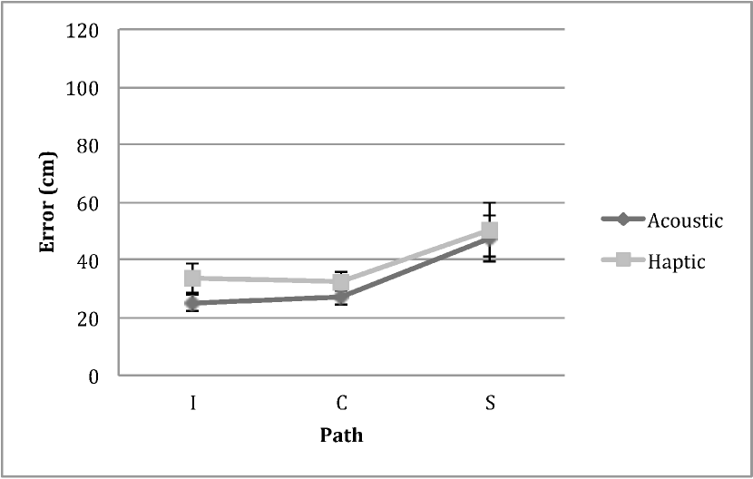
Error Descriptive statistics of error are reported in Fig. 5 (a) as a function of Guidance and Path. The ANOVA highlighted a significant effect for Guidance , , Path , and for the interaction , . Post-hoc pairwise comparison (Tab. 6.1.6) indicated that the mechanical guidance differed significantly from all the others () being the most precise. Moreover, the acoustic guidance was significantly different from the haptic (). Post-hoc comparisons indicated that the I path was significantly easier from the other two ().
 |
 |
| (a) | (b) |
 |
 |
| (c) | (d) |
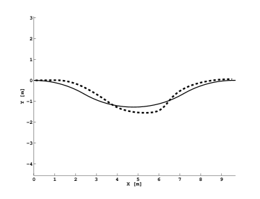
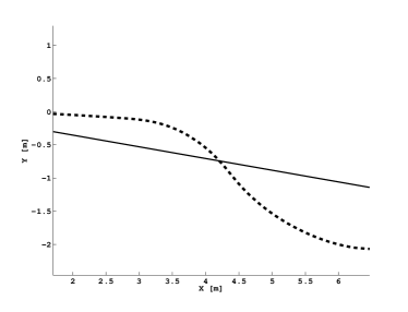
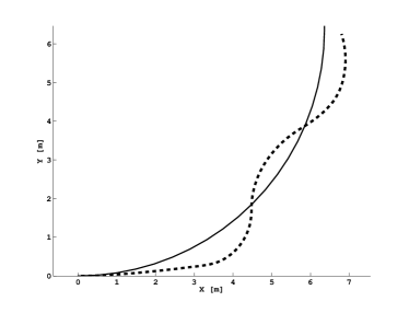
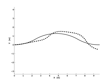
In the mechanical guidance condition, the error was not affected by the path and showed very low variability among participants. On the contrary, for all other conditions there was an effect of Path on the magnitude of the error. Mostly for the haptic, but also for the acoustic guidance, the S path had the highest error. Interestingly, for the binaural guidance, the highest error emerged with the C path. Fig. 6 shows some qualitative results of the experiments.
| Guidance | I | C | S | Average | \pbox 5cmPairwise |
| comparison | |||||
| Acoustic | 33.0 | 32.2 | 53.7 | 39.6 | I vs. S, C vs. S, |
| Haptic | 55.0 | 57.4 | 109.7 | 74.0 | I vs. C and S, |
| Mechanical | 17.1 | 18.3 | 18.8 | 18.1 | n.s. |
| Binaural | 42.1 | 86.3 | 58.7 | 62.4 | I vs. C, |
| Average | 36.8 | 48.6 | 60.2 | ||
| \pbox 5cmPairwise | |||||
| comparison | M vs. A and H, A vs. H, | A vs. H and M, A vs. B, M vs. H and B, | M vs. all, , H vs. A and B, |
 |
 |
| (a) | (b) |
 |
 |
| (c) | (d) |
Time The ANOVA on time showed a significant effect for Guidance , , Path , and for the interaction , . Fig. 5 (b) shows the average time in relation to both Guidance and Path. Post-hoc pairwise comparison showed that the mechanical guidance system was significantly faster than the haptic (), and that the I path differed significantly from the S path (). Walking time was independent of Path for the mechanical and the binaural guidance. Conversely, the S path was performed significantly slower than the I path for both the acoustic and the haptic guidance. The average time and the results of the post-hoc pairwise comparisons are summarized in Tab. 6.1.6.
| Guidance | I | C | S | Average | \pbox 5cmPairwise |
| comparison | |||||
| Acoustic | 25.8 | 26.7 | 28.1 | 26.9 | I vs. S, |
| Haptic | 27.7 | 28.7 | 30.7 | 29.0 | I vs. S, |
| Mechanical | 25.0 | 25.1 | 26.0 | 25.4 | n.s. |
| Binaural | 25.3 | 28.9 | 25.6 | 26.6 | n.s. |
| Average | 26.0 | 27.3 | 27.6 | ||
| \pbox 5cmPairwise | |||||
| comparison | n.s. | n.s. | H vs. M and B, |
Length Only two participants (both in the S path and the binaural guidance condition) walked less than the optimal path length. The ANOVA showed a significant effect for Guidance , , Path , and for the interaction , . Post-hoc comparisons indicated that the haptic guidance differed significantly from all the others ( mechanical and acoustic and binaural). Moreover, the mechanical guidance differed significantly from the acoustic (). The I path differed significantly from the C () and S () paths (Tab. 6.1.6). The haptic guidance showed the worst result in the S path. For the mechanical condition, the performance was different between the I and S path. For the binaural condition there was no effect of Path. Fig. 5 (c) shows the average length in relation to both Guidance and Path.
| Guidance | I | C | S | Average | \pbox 5cmPairwise |
| comparison | |||||
| Acoustic | 10.62 | 10.92 | 11.3 | 10.9 | \pbox 5cmI vs. C, |
| I vs. S, | |||||
| Haptic | 11.76 | 12.12 | 14.08 | 12.7 | \pbox 5cmS vs. I, |
| S vs. C, | |||||
| Mechanical | 10.18 | 10.44 | 10.5 | 10.4 | I vs. S, |
| Binaural | 10.31 | 12.72 | 10.32 | 11.1 | n.s. |
| Average | 10.7 | 11.6 | 11.6 | ||
| \pbox 5cmPairwise | |||||
| comparison | M vs. A, | M vs. H, M vs. A | \pbox 5cmall the | ||
| comparisons | |||||
| except | |||||
| M vs. A, | |||||
| and M vs. B | |||||
| not significant |
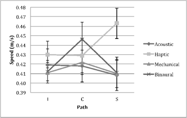
Speed The analysis of variance on speed reported only a significant interaction between Guidance and Path , . Fig. 5 (d) reports the average time as a function of experimental conditions. The average speed and the results of the post-hoc pairwise comparisons are summarized in Tab. 6.1.6. Participants were particularly fast walking the S path.
| Guidance | I | C | S | Average | \pbox 5cmPairwise |
| comparison | |||||
| Acoustic | 0.42 | 0.42 | 0.41 | 0.42 | n.s. |
| Haptic | 0.43 | 0.43 | 0.46 | 0.44 | I vs. S, |
| Mechanical | 0.41 | 0.42 | 0.41 | 0.41 | n.s. |
| Binaural | 0.41 | 0.45 | 0.41 | 0.42 | n.s. |
| Average | 0.42 | 0.43 | 0.42 | ||
| \pbox 5cmPairwise | |||||
| comparison | n.s. | n.s. | A vs. H, M vs. H, |
6.1.7 Questionnaire
Participants scores to the the four questionnaire items were normalized for each participant in relation to the highest score provided among all the answers. The ANOVA indicates that the mechanical guidance is perceived as easier to use with no other significant differences among the other systems. The same results have emerged in relation to the confidence to maintain the correct trajectory. Concerning the acceptability to use the guidance systems in public spaces, the mechanical guidance was again the preferred one in relation to both the acoustic and binaural while no difference has emerged in relation to the haptic. Finally, participants liked the mechanical guidance the most in relation to both haptic and acoustic systems, while no difference has emerged in relation to the binaural one.
Participants spontaneously commented that the mechanical system was easy to follow and required little attention. However, some of them complained that it might be perceived as coercive and risky due to possible errors in route planning. Other people worried about the dangerous effect of a quick turn of the wheels mostly for older users. Participants reported a general dislike about wearing headphones mostly because they might miss important environmental sounds and because of the look. Most of the participants agreed that the binaural condition required more attention than all the other systems. Participants however appreciated that it was something new, interesting and provided a constant feedback on the position. Most of them preferred the binaural system to the acoustic one because it provided more information, yet some reported a difficulty in discriminating the direction the sound was coming.
Most of the participants reported to prefer the haptic guidance system to the acoustic, as easier and less intrusive. In relation to the both guidance condition, participants complained about the poverty of the left and right instructions and the lack of a modulation. Some participants suggested possible ways to increase communication richness, such as, for the acoustic system, different volume indicating the magnitude; verbal feedback; different tones in relation to the angle. For the haptic system comments included modulating the frequency of the vibration in relation to the magnitude of the correction. Some participants reported a kind of annoyance for the haptic stimulation but only for the first minutes of use.
6.1.8 Discussion
The aim of this study was to gather quantitative and qualitative information in relation to the evaluation of four different guidance systems. To this aim participants had the opportunity to navigate non-visible paths (i.e., virtual corridors) using four the different guidance systems. To maintain the correct trajectory participants could only rely on the instructions provided by the c-Walker and, after using each system, they were asked to provide feedback.
As expected, in terms of performance, the mechanical guidance was the most precise. Although an error emerged because of the freedom left to participants, the results show the consistency of the deviation along the different paths, a low variability among the participants and a slight difference in relation to the shape of the paths. The results of the questionnaire further support quantitative data showing that, on average, participants liked the mechanical guidance the most in relation to easiness, confidence in maintaining the trajectory, acceptability and overall judgment. The only concern for some users was that it might be perceived as coercive and risky due to possible errors in route planning. In fact, the mechanical guidance was active in the sense that participants had to passively follow the trajectory imposed by the walker. Differently, in the other three guidance systems, the participants were actively driving based on the interpretation of the provided instructions. In the acoustic guidance, there were only left and right sounds while in the binaural guidance, the sound was modulated by modifying the binaural difference between the two ears. Although more informative, in terms of quantifying the angle of the suggested trajectory, the binaural guidance system emerged to be worse than the acoustic system in the C path. However, it is likely that with adequate training the performance with the binaural system could improve a lot. The results of the questionnaire suggest that both the systems using headphones were not very acceptable because of the possibility to miss environmental sounds and because of the look. Moreover, the binaural system was reported to require more attention than the acoustic one, although no difference emerged in terms of confidence in maintaining the correct trajectory. Overall, the binaural guidance was appreciated because it was something new and provided detailed information. Indeed, most of the participants’ suggestions related to the acoustic and haptic guidance systems were addressed at codifying the instructions in terms of the angle of the correction.
Significant performance differences emerged between the haptic and the acoustic guidance, which could in part be explained by the natural tendency to respond faster to auditory stimuli rather than to tactile stimuli, and in part by the different algorithm employed in the evaluation. This issue is addressed in the second study presented in this paper. Looking at participants performance however it is evident that, independent of the communication channel, the dichotomous nature of the stimulation (left-right) tended to stimulate long left and right corrections leading to zigzagging. One participant explicitly mentioned this feeling while commenting on the haptic guidance. In terms of user experience, the haptic guidance was perceived as more acceptable than the acoustic and the binaural systems, and no different from the mechanical one. Indeed, most of the participants commented that the haptic bracelets could be hidden and did not interfere with the environmental acoustic information.
6.2 Study 2
This evaluation study was designed to clarify the differences emerged in study 1 between the haptic and the acoustic guidance. To this aim both input devices (bracelets and headphones) were interfaced to the same guidance algorithm and tested following the same experimental protocol as study 1, except that participants were required to test only the acoustic and the haptic guidance systems. Moreover, the haptic guidance system was modified using the acoustic guidance algorithm. In this way, we could test directly the effect of the interface. Ten participants (2 females, mean age 30 years old range 24-35) took part in the study.
6.2.1 Results
Descriptive statistics of error are reported in Fig. 7 as a function of Guidance and Path. The ANOVA showed a significant effect for the factor Path , but not Guidance. The post-hoc pairwise comparison showed that the S path differed significantly from the other two () confirming its higher complexity.
The ANOVA on time, length, and speed returned the same trend of results: a main effect only for Path. The analysis of the questionnaire confirmed a preference for the acceptability of the haptic guidance in public spaces. Finally, a between-study analysis of variance comparing the performance of participants using the sound system in study 1 and study 2 returned no significant differences due to study, path, or their interaction.
6.2.2 Discussion
The study indicates that the haptic and acoustic interfaces do not differ in terms of performance, and that the results of study 1 may be attributed entirely to the different algorithms tested. Furthermore, they confirm a preference for the haptic guidance but only regarding its social acceptability in public spaces. Furthermore, the similarities in both performance and user-experience of the acoustic guidance in the two studies is an indicator of the strong reliability and external validity of the evaluation protocol.
Tab. 5 propose a ranking of the 4 guidance systems, combining empirical observations, measurements and participants’ comments in both studies. The best guidance was no doubt the mechanical one, followed by the haptic, acoustic and binaural systems. The evaluations highlighted new challenges for the sociotechnical design of future guidance system. In particular a major issue emerged with regards to the acceptability of the practical requirement of wearing headphones. The binaural system was perceived as a promising solution which captured the user attention. However, more work is needed in order to improve the communication of the directional information.
| Performance | Easiness | Confidence | Acceptability | Total | |
| Acoustic | ++ | ++ | ++ | + | 7 |
| Haptic | ++ | ++ | ++ | +++ | 9 |
| Mechanical | ++++ | +++ | +++ | +++ | 13 |
| Binaural | + | + | ++ | + | 5 |
7 Conclusions
In this paper we have presented four different solutions for guiding a user along a safe path using a robotic walking assistant. One of them is “active” meaning that the system is allowed to “force a turn” in a specified direction. The other ones are “passive” meaning that they merely produce directions that the user is supposed to follow on her own will. We have described the technological and scientific foundations for the four different guidance systems, and their implementation in a device called c-Walker.
The systems has been thoroughly evaluated with a group of young volunteers, allowing us to test the methodology, and providing a baseline for future tests with potential elderly users. This paper contributed a novel evaluation protocol for comparing the different guidance systems, and opens new challenges for interaction designers. The use of virtual corridors allowed us to test the precision of the guidance systems to maintain the correct trajectory in the absence of any visual indications of the route. However, in a real-life scenario, users would most likely walk along a wide corridor with walls on the left and right that might help maintaining a straight path in a particular part of the corridor (i.e., in the centre or towards the left/right). Moreover, corridors’ crossings are often orthogonal. In such scenarios, left and right instructions might be enough to allow the user to reach their goal and the haptic solution could be the best trade off among precision, freedom and cognitive workload, leaving vision and audition free to perceive environmental stimuli. Future research, will repeat this study in more ecological contexts.
From the technical point of view, an interesting future direction is the implementation of guidance solutions based on the use of electromechanical brakes, along the lines suggested in our previous work FontanelliGPP13 .
References
- [1] A. Arias and U. Hanebeck. Wide-area haptic guidance: Taking the user by the hand. In Proc. IEEE/RSJ Int. Conf. Intel. Robots Syst., pages 5824–5829, 2010.
- [2] J. Blauert. Spatial Hearing-Revised Edition: The Psychophysics of Human Sound Localization. MIT press, 1996.
- [3] J. T. Cacioppo and L. C. Hawkley. Perceived social isolation and cognition. Trends in Cognitive Sciences, 13(10):447 – 454, 2009.
- [4] O. Chuy, Y. Hirata, and K. Kosuge. A new control approach for a robotic walking support system in adapting user characteristics. Systems, Man, and Cybernetics, Part C: Applications and Reviews, IEEE Transactions on, 36(6):725–733, 2006.
- [5] O. Y. Chuy, Y. Hirata, Z. Wang, and K. Kosuge. A control approach based on passive behavior to enhance user interaction. Robotics, IEEE Transactions on, 23(5):899–908, 2007.
- [6] A. Colombo, D. Fontanelli, A. Legay, L. Palopoli, and S. Sedwards. Motion planning in crowds using statistical model checking to enhance the social force model. In Decision and Control (CDC), 2013 IEEE 52nd Annual Conference on, pages 3602–3608. IEEE, 2013.
- [7] A. Colombo, D. Fontanelli, A. Legay, L. Palopoli, and S. Sedwards. Motion Planning in Crowds using Statistical Model Checking to Enhance the Social Force Model. In Proc. IEEE Int. Conf. on Decision and Control, pages 3602–3608, Florence, Italy, 10-13 Dec. 2013. IEEE.
- [8] J. B. F. V. Erp, H. A. H. C. V. Veen, C. C. Jansen, and T. Dobbins. Waypoint navigation with a vibrotactile waist belt. ACM Trans. Appl. Percept., 2(2):106–117, 2005.
- [9] D. Fontanelli, A. Giannitrapani, L. Palopoli, and D. Prattichizzo. Unicycle Steering by Brakes: a Passive Guidance Support for an Assistive Cart. In Proceedings of the 52nd IEEE International Conference on Decision and Control, pages 2275–2280, 10-13 Dec. 2013.
- [10] G. A. Gescheider, S. J. Bolanowski, K. L. Hall, K. E. Hoffman, and R. T. Verrillo. The effects of aging on information-processing channels in the sense of touch: I. absolute sensitivity. Somatosens Mot Res., 11(4):345–357, 1994.
- [11] A. Ghosh, L. Alboul, J. Penders, P. Jones, and H. Reed. Following a robot using a haptic interface without visual feedback. In Proc. Int. Conf. on Advances in Computer-Human Interactions, pages 147–153, 2014.
- [12] I. Karuei, K. E. MacLean, Z. Foley-Fisher, R. MacKenzie, S. Koch, and M. El-Zohairy. Detecting vibrations across the body in mobile contexts. In Proc. Int. Conf. on Human Factors in Computing Systems, pages 3267–3276, 2011.
- [13] S. Keates and J. Clarkson. Countering design exclusion. In Inclusive Design, pages 438–453. Springer, 2003.
- [14] G. Lee, T. Ohnuma, and N. Y. Chong. Design and control of jaist active robotic walker. Intelligent Service Robotics, 3(3):125–135, 2010.
- [15] A. Micaelli and C. Samson. Trajectory tracking for unicycle-type and two-steering-wheels mobile robots. 1993.
- [16] P. Nazemzadeh, D. Fontanelli, and D. Macii. An Indoor Position Tracking Technique based on Data Fusion for Ambient Assisted Living. In 2013 IEEE Intl. Conf. on Computational Intelligence and Virtual Environments for Measurement Systems and Applications, pages 7–12, Milan, Italy, 15-17 July 2013. IEEE.
- [17] P. Nazemzadeh, D. Fontanelli, D. Macii, and L. Palopoli. Indoor positioning of wheeled devices for ambient assisted living: A case study. In Instrumentation and Measurement Technology Conference (I2MTC) Proceedings, 2014 IEEE International, pages 1421–1426, May 2014.
- [18] P. Nazemzadeh, D. Fontanelli, D. Macii, and L. Palopoli. Indoor Positioning of Wheeled Devices for Ambient Assisted Living: a Case Study. In Proc. IEEE Int. Instrumentation and Measurement Technology Conference (I2MTC), pages 1421–1426, Montevideo, Uruguay, May 2014. IEEE.
- [19] L. Palopoli et al. Navigation assistance and guidance of older adults across complex public spaces: the DALi approach. Intelligent Service Robotics, pages 1–16, 2015.
- [20] L. Rizzon and R. Passerone. Embedded soundscape rendering for the visually impaired. In Industrial Embedded Systems (SIES), 8th IEEE International Symposium on, pages 101–104. IEEE, 2013.
- [21] L. Rizzon and R. Passerone. Spatial sound rendering for assisted living on an embedded platform. In Applications in Electronics Pervading Industry, Environment and Society, volume 289 of Lecture notes in Electrical Engineering, pages 61–73. Springer, 2014.
- [22] M. Saida, Y. Hirata, and K. Kosuge. Development of passive type double wheel caster unit based on analysis of feasible braking force and moment set. In Proceedings of the 2011 IEEE/RSJ International Conference on Intelligent Robots and Systems, pages 311–317, 2011.
- [23] S. Scheggi, M. Aggravi, and D. Prattichizzo. A vibrotactile bracelet to improve the navigation of older adults in large and crowded environments. In Proc. 20th IMEKO TC4 Int. Symp. and 18th Int. Workshop on ADC Modelling and Testing Research on Electric and Electronic Measurement for the Economic Upturn, pages 798–801, 2014.
- [24] S. Scheggi, F. Morbidi, and D. Prattichizzo. Human-robot formation control via visual and vibrotactile haptic feedback. IEEE Trans. on Haptics, 2014.
- [25] D. Soetanto, L. Lapierre, and A. Pascoal. Adaptive, non-singular path-following control of dynamic wheeled robots. In IEEE Conf. on Decision and Control, volume 2, pages 1765–1770. IEEE, 2003.
- [26] C. Urdiales, J. M. Peula, M. Fdez-Carmona, C. Barrué, E. J. Pérez, I. Sánchez-Tato, J. Del Toro, F. Galluppi, U. Cortés, R. Annichiaricco, et al. A new multi-criteria optimization strategy for shared control in wheelchair assisted navigation. Autonomous Robots, 30(2):179–197, 2011.
- [27] G. Wasson, P. Sheth, M. Alwan, K. Granata, A. Ledoux, and C. Huang. User intent in a shared control framework for pedestrian mobility aids. In Intelligent Robots and Systems, 2003.(IROS 2003). Proceedings. 2003 IEEE/RSJ International Conference on, volume 3, pages 2962–2967. IEEE, 2003.
- [28] S. Weinstein. Intensive and extensive aspects of tactile sensitivity as a function of body part, sex, and laterality. In The skin senses, pages 195–218. Erlbaum, 1968.
- [29] C. R. Wilkinson and A. De Angeli. Applying user centred and participatory design approaches to commercial product development. Design Studies, 35(6):614–631, 2014.
- [30] C. R. Wilkinson, A. De Angeli, et al. Demonstrating a methodology for observing and documenting human behaviour and interaction. In DS 77: Proceedings of the DESIGN 2014 13th International Design Conference, 2014.