Substrate-assisted 2D DNA lattices and algorithmic
lattices from single-stranded tiles†
Junghoon Kim,a Tai Hwan Ha,b
and Sung Ha Park∗a,c
We present a simple route to circumvent kinetic traps which affect many types
of DNA nanostructures in their self-assembly process. Using this method, a new
2D DNA lattice made up of short, single-stranded tile (SST) motifs was
created. Previously, the growth of SST DNA assemblies was restricted to 1D
(tubes and ribbons) or finite-sized 2D (molecular canvases). By utilizing the
substrate-assisted growth method, sets of SSTs were designed as unit cells to
self-assemble into periodic and aperiodic 2D lattices which continuously grow
both along and orthogonal to the helical axis. Notably, large-scale (1
m2) fully periodic 2D lattices were fabricated using a minimum of just
2 strand species. Furthermore, the ability to create 2D lattices from a few
motifs enables certain rules to be encoded into these SSTs to carry out
algorithmic self-assembly. A set of these motifs were designed to execute
simple 1-input 1-output COPY and NOT algorithms, the space-time manifestations
which were aperiodic 2D algorithmic SST lattices. The methodology presented
here can be straightforwardly applied to other motifs which fall into this
type of kinetic trap to create novel DNA crystals.
Introduction
Spatial and temporal control of matter down to the smallest attainable scale is an ongoing challenge in many fields such as supramolecular chemistry, material science, and physics. The relatively nascent field of DNA nanotechnology has provided some proven methods of bottom-up self-assembly to tackle these problems. One of the core developments in this field has been the creation of self-assembled DNA crystals in 1-,1, 2, 3, 4 2-,5, 6, 7, 8, 9 and 3-10dimensions. The overwhelming majority of these works have utilized the tile-based method where the oligonucleotides first self-assemble into rigid constituent building-blocks (tiles) which in turn bind according to their respective sticky-ends to form crystals during the annealing process. A more direct and simpler route of creating DNA crystals where extremely simple single strands of DNA called single-stranded tiles (SSTs), which are effectively made up of only the sticky-ends thereby bypassing the tile body formation phase, was proposed by Yin et al.3 The types of crystals made in that work were those of the tube and ribbon types, inherently preserving the translational symmetry to only one direction and restricting the growth of the crystal to 1D, namely along the helical axis. More recently, SSTs have been programmed to self-assemble into complex 2 and 3D shapes by way of creating finite-sized molecular canvases11, 12 analogous to what DNA origami13, 14 had antecedently achieved.
Despite the successes that have been accomplished in DNA self-assembly, a chronic problem in the rational design of DNA nanostructures is our lack of understanding of the self-assembly kinetics. The existence of kinetic traps which affects the self-assembly kinetics of many structures makes the route going from structure design to target structure formation a very nontrivial process.15 In this regard, one prevalent type of kinetic trap which manifests itself during the self-assembly process is the circularization of structures to form 1D tubes (such as the aforementioned SST tubes), although according to their design principles these structures should be able to form periodic 2D lattices. Examples include motifs such as triple-crossover tiles,1 cross-tiles,6 DAE-type double-crossover (DX) tiles,16, 17 DX-like structures,18 and SSTs,3, 11 all of which show tube formation behavior. Here we present a method to avoid this type of kinetic trap and use it to create a significant molecular construct which has been lacking, i.e., a periodic 2D SST lattice which retains translational symmetry in both orthogonal directions allowing full 2D crystal growth. Furthermore, as tile-based algorithmic self-assembly was an integral advancement in molecular computing,19, 20, 21 we show that these SSTs can also carry out computations to form 2D algorithmic SST lattices.
Results and discussion
Each SST motif is a 42-base oligonucleotide divided into 4 modular domains. The modular domains are designed so that between complementary strands, the odd-numbered domains (domains 1 and 3) bind together and the even-numbered domains (domains 2 and 4) bind together [Figure 1a, electronic supplementary informtion (ESI) section LABEL:SI:sequencemap]. Starting from the 5′-end, each strand forms part of a helix up to the first 21 bases (2 full-turns) and then crosses over where the remaining 21 bases form part of the adjacent helix in the opposite direction. From this design, we can see these strands self-assemble into adjoining helices with each adjacent helix having single-stranded cross-over junctions spaced 21 bases apart. The tubes formed from this design have circumferences which can be controlled by the number of different strands, , used. For example, for a tube of (a 6-helix tube or 6-HT, Figure 1b), we design 6 different SSTs so that domains 3 and 4 (the top-half) of strand 1 are complementary to domains 1 and 2 (the bottom-half) of strand 2, respectively, domains 3 and 4 of strand 2 are complementary to domains 1 and 2 of strand 3, respectively, and so forth up until the top-half of strand 6 is complementary to the bottom-half of strand 1. One might (wrongfully) conclude that a set of these strands would act as a unit cell and lead to 2D lattice formation since, after nucleation, growth is possible both along and orthogonal to the helical axis. Also, another theoretically conceivable scenario is the formation of polydisperse -helix tubes (where , , e.g., 12-helix tubes for and ). Instead, Yin et al. postulated that the energy landscape is such that the tubes are trapped at a free energy local minimum in which monodisperse 6-HTs are highly favored, terminating any growth orthogonal to the helical axis once bindings occur to close the tubes.3 For continued crystal growth orthogonal to the helical axis, this cyclization must somehow be prevented by offsetting this kinetic trap. Although the origins of this kinetic trap have not been experimentally verified, one plausible possibility is the existence of a nucleation barrier between -helix tubes and -helix tubes which would naturally explain the monodispersity of the tube circumferences for a given .
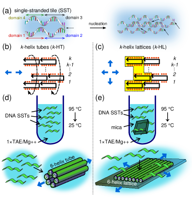
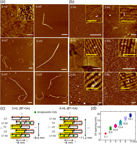
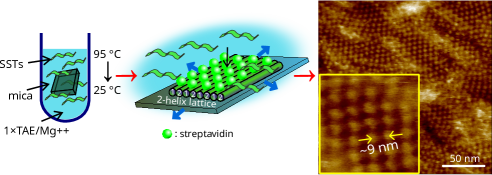
Our strategy is to remove this barrier so growth can continue and form 2D lattices which preserve translational symmetry in both directions (Figure 1c). This can be achieved by the substrate-assisted growth (SAG) method, where a small sheet of mica (or other substrates with siloxy groups at its surface such as fused silica or quartz) is inserted into the solution vessel at the start of the annealing process (Figure 1e).4 The addition of the mica substrate into the solution provides preferential nucleation sites which significantly reduces the kinetic barrier to nucleation (as compared to free-solution annealing) and changes the nucleation mechanism from a homogeneous to a heterogeneous one. This is consistent with observations from previous studies of SAG methods where the saturation concentration, i.e., the concentration at which nucleated seeds start to form, was found to be reduced by roughly an order of magnitude.22 By offsetting the kinetic trap, adjoining helices are no longer forced into tubular structures (Figure 1d), i.e., -helix tubes (-HT), but rather form well-defined 2D lattices, i.e., -helix lattices (-HL), on the mica surface (Figure 1e). Figure 2 shows atomic force microscopy (AFM) data of the structures assembled from SSTs via free-solution annealing and substrate-assisted annealing for through 7, respectively. As can be seen from the images, 2D lattices possessing translational symmetry in both orthogonal directions were successfully fabricated going as far as using just 2 strand species (). Although the kinetics of the system favors the formation of 2-helix wide linear chains (2-HT) under free-solution annealing, evidence strongly suggests that when mica is added to the system pre-annealing, the assembly pathway is altered such that adjoining helical lattices are highly favored (see ESI Figure LABEL:SIfig:AFM and ESI Figure LABEL:SIfig:AFM2 for AFM measurements). It is worth noting that in a work by Liu et al.,18 1 strand specie was used to form DX-like tiles, but assembly of these tiles also fall into the trap of rolling up to form tubes instead of 2D lattices. The authors of that work assert that the tubes are kinetically favored over 2D lattices thus keeping the translational symmetry in only one direction. To check 2D lattice formation in our work, the first strand (U1-bt) of each -HL set was biotinylated at a specified site (Figure 2c). If 2D lattices do indeed form for all , the spacings between these biotinylated (BT) sites running orthogonal to the helical axis would increase proportional to and could be measured by AFM when bound to streptavidin (SA). Figure 2b clearly shows 2D periodic arrangements of SA sites with increasing spacings proportional to for all . Figure 2d shows measurements of 10 randomly chosen pairs of neighboring SA sites orthogonal to the helical axis taken from AFM images for each along with their averages (see also ESI Figure LABEL:SIfig:AFM2). The data is in good agreement with predictions given that a single DNA duplex has a measured width of nm (ESI Figure LABEL:SIfig:AFM), e.g., the predicted SA spacing for 4-HL is whereas the measured average is 10.9 nm. For all values of tested, the surface morphology of -HLs remained the same at 50 nM strand concentrations, i.e., fully covered single-layered 2D helical lattices on a mica substrate (see ESI Figure LABEL:SIfig:frac for an analysis of the fractional coverage dependence on strand concentration).
Another important aspect we addressed in this work was the creation of algorithmic 2D crystals from SSTs. We will compare SSTs with one of the most popular motifs used for algorithmic self-assembly, the DX tile,23, 5, 20 since the geometric topology of both motifs can be abstracted in the same manner, i.e., both have 4 sticky-ends acting as Wang tile edges.24, 25 In principle, there are several advantages of implementing algorithms using SST motifs. First, the information density of an SST crystal is more than three times higher than DX crystals. The theoretical area of a single DX motif is 50.32 () nm2 whereas for an SST motif it is 14.28 () nm2. This provides a more intricate platform with a higher resolution in which algorithms can be carried out compared to tile-based algorithmic self-assembly. Second, within the kinetic Tile Assembly Model,26 the longer sticky-ends of SSTs allows for much more favorable “correct” associations between motifs, thereby reducing the overall error rate of the algorithmic crystal. More specifically, at equilibrium, a correct tile association is favored over an incorrect tile association (an error) by a factor of , where is the amount of free energy needed to break a single sticky-end bond and is directly proportional to the sticky-end length. Hence, with all other factors being equal, correct sticky-end bindings between SST motifs, which have two different lengths of 10 and 11 nucleotides, are exponentially more likely compared to sticky-end bindings between the 5-nucleotide sticky-ends of DX tiles (, where and are the ratios of correct tile associations over error associations of the SSTs and DX tile sticky-ends, respectively, and are directly proportional to their respective sticky-end lengths). Third, the longer sticky-ends also allow a much bigger design space (by more than 3 orders of magnitude), thereby avoiding unwanted bindings among similar sticky-ends. Also, to a lesser extent, by circumventing the body formation phase, spurious bindings which may occur during body formations and their erroneous crystal offshoots which follow, can be avoided.
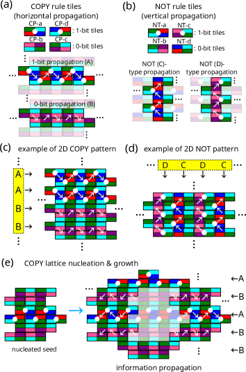
Here we show two primitive 1-input 1-output logic operations, COPY and NOT, in the form of SST motifs (Figure 3). Figure 3a and b show individual SST motifs used for each logic operation abstracted as 4-color rectangles, where each domain of each motif is color-coded. Matching colors of the top and bottom edges of the rectangle represent complementarity and bindings occur through these edges. For both COPY and NOT operations, 4 SSTs, 2 0-bit and 2 1-bit tiles, were designed to carry out each algorithm. Of the 4 sticky-ends of each SST, 2 sticky-ends were encoded as inputs/outputs and 2 were designed to be common in all 4 of the motifs. These common sticky-ends (cyan and green colored domains) are meant not to propagate information but to act as binding domains so that the algorithmic lattice can grow beyond the 1 dimension which is sufficient for 1-input 1-output type algorithmic crystals (Figure 3a-e). Since both COPY and NOT operations are reversible, each information carrying sticky-end can act as both an input and output. The 4 COPY and NOT SSTs are labeled as CP- and NT-, respectively, where a, b, c, or d. CP-a, -d (NT-a, -c) represent 1-bit tiles and CP-b, -c (NT-b, -d) represent 0-bit tiles for COPY (NOT) logic gates. To experimentally differentiate 1-bit and 0-bit SSTs, 1-bit strands were biotinylated at the appropriate locations (ESI, section LABEL:SI:sequencemap) so that they could bind with SA molecules which were added just before AFM imaging.
Once nucleation occurs, crystal growth is dictated by the Tile Assembly Model. Much akin to algorithmic self-assembly of DX tiles, algorithmic lattice growth happens when 2-bindings of the SSTs are thermodynamically much more favored than 1-bindings. In addition, since SSTs have much longer sticky-ends than DX tiles, error rates can be expected to be substantially lower than DX algorithmic crystals. For COPY lattices, we label the propagation of 1-bit information as “A” and 0-bit information as “B” (Figure 3a). Analogously, for NOT crystals, where an input of a 0-bit motif leads to a binding with a 1-bit motif (and vice-versa), there are 2 types of information propagating bindings, types “C” and “D” (Figure 3b). Any random combination of A’s and B’s or C’s and D’s constitute a single COPY or NOT 2D algorithmic lattice, respectively, of which one example of each pattern is shown in Figure 3c and d. On a side note, the direction of information propagation can only be determined insofar as the crystal growth direction can be determined and cannot be further specified so the information propagation (white) arrows in Figure 3(a-d) may just as well point in the opposite direction. Figure 3e shows the direction of information propagation after nucleation for a COPY lattice. Once a nucleated seed forms, the direction of information propagation points away from the seed, i.e., parallel (orthogonal) to the helical axis for the COPY (NOT) tiles designed in this work.
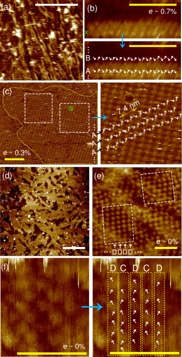
Typically observed crystal sizes were on the scale of several hundred nm2 to m2 for both periodic and aperiodic crystals, but the crystal sizes were likely limited by the SAG method since the lack of control of the nucleation sites on the substrate surface restricts a single crystal from growing beyond a certain size before encountering other nucleation seeds or crystals on the surface [Figure 4a (COPY) and d (NOT), with detailed analysis of magnified regions shown in Figure 2b (COPY) and f (NOT)]. Hence, it is sometimes difficult to verify the exact boundaries of a single crystal on a fully covered mica surface as partially formed crystals seem to join together at some of the lattice edges. Some of the formed lattices showed biased formations where whole lattices were made up of solely A- or B-type (C- or D-type) propagations for COPY (NOT) lattices (Figure 2c and e), which is a possibility due to the design of the tiles. This suggests that there may be a difference in binding affinities of the tiles making up A- and B-type (C- and D-type) propagations. Large portions of these biased lattices showed very few, if any, errors. Figure 2c (right) shows a magnified region of a biased COPY lattice (delineated by the dashed white lines) where a very periodic arrangement of SA sites with spacings of nm can be observed (A-type propagations). One site, indicated by the dashed yellow circle, may indicate an error binding but it is more likely that a SA molecule did not bind at that site or was displaced by the AFM tip during imaging.
Conclusions
We have shown here how to avoid a prevalent type of kinetic trap in DNA self-assembly and were successful in creating novel periodic 2D SST lattices hundreds of nm2 to m2 from a small set of strands (with a minimum of ) using this method. Motivational differences aside, creating 2D DNA canvases of similar sizes requires upwards of several hundred SST strand species (up to 777 for a 2D rectangular canvas) making large-scale 2D lattices rather cumbersome and inefficient.11 Moreover, the SAG method allows for algorithmic self-assembly using the simplest of DNA motifs, a single oligonucleotide, with the possibility to create highly complex, fully addressable patterns. Although some preliminary theoretical and experimental studies of SAG DNA nanostructures exist,4, 27, 28, 29 elucidating the precise assembly pathway remains a vital next step in further exploiting any surface-assisted DNA self-assembly. This is important if we consider the vast potential DNA structures may hold in modern electronic applications, a sizable portion which is based on technologically important materials with surface siloxy groups, e.g., silica.28 From our study, it seems that under conventional annealing protocols in a TAE/Mg2+ buffer, non-specific adsorption of the SSTs onto the mica surface after which 2D diffusion-based self-assembly occurs is favored over 3D diffusion-based (free-solution) self-assembly and adsorption. By providing favorable nucleation sites, the mica substrate traps the free floating oligonucleotides near the surface (within the Debye length) via the Mg2+ counter-ions and expedites the reactions of self-assembly of these trapped DNA strands by reducing the diffusion dimensionality from 3D to 2D. The AFM data corroborates that the kinetics of these reactions are faster than the two-step reaction of 3D diffusion-based self-assembly and adsorption onto the mica surface. This type of reduction in the degree of freedom (diffusion dimensionality) has been cited as the cause of accelerations in reaction rates of receptor-ligand interactions.30 Experimentally verifying the assembly pathway may be possible by obtaining the surface thermal profiles of SAG SST assemblies in combination with real-time fractional coverage measurements during the annealing process. Lastly, the method presented here can be straightforwardly applied to other tile-body-based DNA motifs which circularize to form tube/ribbon structures during free-solution annealing6, 1, 16, 17 to elucidate whether the origins of the circularization are due to the same kinetic trap as the SSTs studied here with the further potential to create novel DNA structures.
Experimental
DNA oligonucleotide synthesis.
Synthetic oligonucleotides were purchased from Bioneer Co. Ltd (Daejeon, Korea) and purified by high performance liquid chromatography (HPLC). Details can be found at www.bioneer.com.
Annealing protocol.
Stoichiometric quantities of each strand species of the -HTs and -HLs were pipetted into AXYGEN-tubes along with a physiological buffer, 1 TAE/Mg2+ [Tris-Acetate-EDTA (40 mM Tris, 1 mM EDTA (pH 8.0), 12.5 mM Mg(Ac)2)]. The microtubes were then shaken for 30 seconds using a vortex mixer and centrifuged at 8,000 rpm for 10 seconds. For the substrate-assisted growth method of the -HLs/COPY/NOT samples, a piece of mm2 mica sheet (Pelco® mica sheets, Ted Pella, Inc.) was placed inside the microtube after centrifuging. The samples were then cooled slowly from 95 ∘C to 25 ∘C by placing the AXYGEN-tubes in 1.5 L of boiled water in a styrofoam box for 24 hours to facilitate hybridization. The strand species concentrations were 200 nM and 50 nM and the final volumes were 100 l and 200 l for the -HTs and -HLs/COPY/NOT samples, respectively.
AFM imaging.
The AFM images of the -HTs were taken by pipetting 5 L of the samples on freshly cleaved mica after which 45 L of 1 TAE/Mg2+ buffer was pipetted onto the mica surface and another 5 L of 1 TAE/Mg2+ buffer was dropped onto the AFM tip (Veeco Inc.). For the -HLs/COPY/NOT samples, the mica sheets were taken out the microtubes and one side blow dried with nitrogen gas after which superglue was lightly applied on the dry side and placed onto a metal puck (Ted Pella, Inc.). 20 L of 1 TAE/Mg2+ buffer was pipetted onto the mica and the metal puck placed on the AFM scanner head for imaging. For biotinylated -HLs/COPY/NOT samples, we added 5 L of 200 nM streptavidin (Rockland Inc.) to the mica surface and let the sample sit for 1 minute before imaging. All AFM images were obtained on a Digital Instruments Nanoscope III (Vecco, USA) with a multimode fluid cell head in tapping mode under a buffer using NP-S oxide-sharpened silicon nitride tips (Vecco, USA).
Acknowledgements
This research was supported by a grant from the Korea Research Institute of Bioscience and Biotechnology (KRIBB) Research Initiative Program (2014) and by the National Research Foundation of Korea (NFR) funded by the Ministry of Science, ICT & Future Planning (MSIP) (NRF-2014R1A2A1A11053213).
References
- Liu et al. 2004 D. Liu, S. H. Park, J. H. Reif and T. H. LaBean, Proc. Natl. Acad. Sci. U. S. A., 2004, 101, 717.
- Park et al. 2005 S. H. Park, R. Barish, H. Li, J. H. Reif, G. Finkelstein, H. Yan and T. H. LaBean, Nano Lett., 2005, 5, 693.
- Yin et al. 2008 P. Yin, R. F. Hariadi, S. Sahu, H. M. T. Choi, S. H. Park, T. H. LaBean and J. H. Reif, Science, 2008, 321, 824.
- Hamada and Murata 2009 S. Hamada and S. Murata, Angew. Chem., Int. Ed., 2009, 121, 6952.
- Winfree et al. 1998 E. Winfree, F. Liu, L. A. Wenzler and N. C. Seeman, Nature, 1998, 394, 539.
- Yan et al. 2003 H. Yan, S. H. Park, G. Finkelstein, J. H. Reif and T. H. LaBean, Science, 2003, 301, 1882.
- Ding et al. 2004 B. Ding, R. Sha and N. C. Seeman, J. Am. Chem. Soc., 2004, 126, 10230.
- He et al. 2005 Y. He, Y. Chen, H. Liu, A. E. Ribbe and C. Mao, J. Am. Chem. Soc., 2005, 127, 12202.
- Malo et al. 2005 J. Malo, J. C. Mitchell, C. Vénien-Bryan, J. R. Harris, H. Wille, D. J. Sherratt and A. J. Turberfield, Angew. Chem., Int. Ed., 2005, 44, 3057.
- Zheng et al. 2009 J. Zheng, J. Birktoft, Y. Chen, T. Wang, R. Sha, P. Constantinou, S. Ginell, C. Mao and N. Seeman, Nature, 2009, 461, 74.
- Wei et al. 2012 B. Wei, M. Dai and P. Yin, Nature, 2012, 485, 623.
- Ke et al. 2012 Y. Ke, L. L. Ong, W. M. Shih and P. Yin, Science, 2012, 338, 1177.
- Rothemund 2006 P. W. K. Rothemund, Nature, 2006, 440, 297.
- Han et al. 2011 D. Han, S. Pal, J. Nangreave, Z. Deng, Y. Liu and H. Yan, Science, 2011, 332, 342.
- Doye et al. 2013 J. P. K. Doye, T. E. Ouldridge, A. A. Louis, F. Romano, P. Šulc, C. Matek, B. E. K. Snodin, L. Rovigatti, J. S. Schreck, R. M. Harrison and P. J. Smith, Phys. Chem. Chem. Phys., 2013, 15, 20395.
- Rothemund et al. 2004 P. W. K. Rothemund, A. Ekani-Nkodo, N. Papadakis, A. Kumar, D. K. Fygenson and E. Winfree, J. Am. Chem. Soc., 2004, 126, 16344.
- Ke et al. 2006 Y. Ke, Y. Liu, J. Zhang and H. Yan, J. Am. Chem. Soc., 2006, 128, 4414.
- Liu et al. 2006 H. Liu, Y. Chen, Y. He, A. E. Ribbe and C. Mao, Angew. Chem., Int. Ed., 2006, 45, 1942.
- Mao et al. 2000 C. Mao, T. H. LaBean, J. H. Reif and N. C. Seeman, Nature, 2000, 407, 493.
- Rothemund et al. 2004 P. W. K. Rothemund, N. Papadakis and E. Winfree, PLoS Biol., 2004, 2, 2041.
- Fujibayashi et al. 2008 K. Fujibayashi, R. Hariadi, S. H. Park, E. Winfree and S. Murata, Nano Lett., 2008, 8, 1791.
- Lee et al. 2013 J. Lee, S. Hamada, S. U. Hwang, R. Amin, J. Son, S. R. Dugasani, S. Murata and S. H. Park, Sci. Rep., 2013, 3, 1–5.
- Fu and Seeman 1993 T.-J. Fu and N. C. Seeman, Biochemistry, 1993, 32, 3211.
- Wang 1961 H. Wang, Bell System Tech J, 1961, 1–42.
- Wang 1962 H. Wang, Technical report BL-30 (II-15), 1962.
- Winfree 1988 E. Winfree, Caltech Technical Report CS-TR:1988.22, 1988.
- Sun et al. 2009 X. Sun, S. Hyeon Ko, C. Zhang, A. E. Ribbe and C. Mao, J. Am. Chem. Soc., 2009, 131, 13248.
- Lee et al. 2011 J. Lee, S. Kim, J. Kim, C.-W. Lee, Y. Roh and S. H. Park, Angew. Chem., Int. Ed., 2011, 50, 9145.
- Hamada and Murata 2012 S. Hamada and S. Murata, RSC Adv., 2012, 2, 7406.
- Adam and Delbrück 1968 G. Adam and M. Delbrück, Structural Chemistry and Molecular Biology, Freeman, 1968, pp. 198–215.
(Keywords : single-stranded tile, DNA structures, substrate-assisted growth, self-assembly, algorithmic self-assembly)