Localized magnetic fields enhance the field-sensitivity of the gyrotropic resonance frequency of a magnetic vortex
Abstract
We have carried out micromagnetic simulations of the gyrotropic resonance mode of a magnetic vortex in the presence of spatially localized and spatially uniform out-of-plane magnetic fields. We show that the field-induced change in the gyrotropic mode frequency is significantly larger when the field is centrally localized over lengths which are comparable to or a few times larger than the vortex core radius. When aligned with the core magnetization, such fields generate an additional confinement of the core. This confinement increases the vortex stiffness in the small displacement limit, leading to a resonance shift which is greater than that expected for a uniform out-of-plane field of the same amplitude. Fields generated by uniformly magnetized spherical particles having a fixed separation from the disk are found to generate analogous effects except that there is a maximum in the shift at intermediate particle sizes where field localization and stray field magnitude combine optimally to generate a maximum confinement.
pacs:
75.70.Kw, 75.78.Cd, 76.50.+gI Introduction
A magnetic vortex is a curled magnetization configuration with an out-of-plane magnetized nano-scale sized core Shinjo et al. (2000); Wachowiak et al. (2002). Vortices arise spontaneously in (sub)micron-scale Guslienko (2008) magnetic elements such as discs Cowburn et al. (1999) (as well as square Vogel et al. (2011) or triangular Yakata et al. (2013) plates) and are of relevance for a range of applications ranging from radiofrequency signal generation Pribiag et al. (2007); Dussaux et al. (2010) and detectionJenkins et al. (2015) to cancer treatment Kim et al. (2010), data storage Yamada et al. (2007) and magnonicsHuber and Grundler (2011); Han et al. (2013); Behncke et al. (2015). Many applications exploit the lowest frequency magnetic excitation of a vortex, the gyrotropic mode Guslienko et al. (2002); Choe et al. (2004); Ivanov (2004); Guslienko et al. (2006), which corresponds to an orbit-like motion of the vortex core about the disk’s center.
An important characteristic of the gyrotropic mode is that its frequency, , can be tuned by applying static out-of-planePribiag et al. (2007); de Loubens et al. (2009); Dussaux et al. (2010); Locatelli et al. (2011) or in-planeYakata et al. (2013); Buchanan et al. (2006) magnetic fields. Uniform out-of-plane magnetic fields modify both the element’s magnetization configuration and the magnetostatic confinement of the core and, when sufficiently far below the saturation field of the disk, induce a change in which is a linear function of the field strength Pribiag et al. (2007); de Loubens et al. (2009); Dussaux et al. (2010). The combination of this field-linearity with the ability to electrically probe vortex dynamics (by fabricating a vortex-based spin torque nano-oscillatorPribiag et al. (2007); Dussaux et al. (2010); Kim (2012), STNO), has application not only for field-tunable electronic oscillators Pribiag et al. (2007); Dussaux et al. (2010); Locatelli et al. (2011); Lebrun et al. (2014) but potentially also for intrinsically frequency-based sub-micron magnetic field sensorsBraganca et al. (2010); Ryan et al. (2011). The latter typically exploit the field dependence of the output frequency of a STNO (e.g. see Braganca et al. (2010); Ryan et al. (2011); Srimani et al. (2015) for non-vortex based devices) for frequency-basedBraganca et al. (2010); Mizushima et al. (2010); Inoue et al. (2011); Atalay et al. (2015); Metaxas et al. (2015) field sensing. One potential application of such a sensor is in the development of frequency-based nano-scale devices to detect (biofunctionalized) magnetic nanoparticlesMetaxas et al. (2015) (MNPs) for in-vitro bio-sensing and point-of-care medical diagnostics Gaster et al. (2009).
In this work we show that central, localized out-of-plane fields (such as those generated by MNPs) produce shifts in the gyrotropic frequency greater than those induced by uniform out-of-plane fields having the same amplitude. It is shown that this is due to an increase in the vortex stiffness as a result of the out-of-plane magnetization of the core preferentially aligning with the strongest part of the localized field. For the particular case of MNPs whose lower surfaces are separated from the disk by a fixed distance, we demonstrate that the frequency shift is characterized by a clear maximum at intermediate particle sizes, a result of an optimized combination of the amplitude and localization of the stray field created by the MNP. We also note that short range structural disorder (as well as domain-generated stray fieldsHeldt et al. (2014)) can also pin vorticesUhlig et al. (2005) (with a potential for quantum depinningZarzuela et al. (2012, 2013)) and that these defects have also been shown to be capable of modifying the gyrotropic mode frequencySilva et al. (2008); Vansteenkiste et al. (2009); Compton et al. (2010); Dussaux et al. (2010); Min et al. (2011); Chen et al. (2012).
II Micromagnetic simulation
Our results were obtained using finite difference micromagnetic simulations of the gyrotropic mode using MuMax3 Vansteenkiste et al. (2014). We will focus on simulation results for NiFe discs with radius nm, thickness nm, saturation magnetization kA/m, exchange stiffness pJ/m, magnetic damping , no intrinsic anisotropy and a cell size of nm3. To begin with, the system is initialized with a vortex-like magnetic configuration and allowed to relax using MuMax3’s internal relaxation routine which time evolves the magnetization (without precession) using energy- and then torque-minimization as stopping criteriaVansteenkiste et al. (2014). A transverse magnetic field sinc pulse is then applied with an amplitude of 2 mT, a time offset of 300 ps and a cut-off frequency of 30 GHz. This induces a displacement of the vortex core (as well as some higher frequency excitationsIvanov and Zaspel (2002, 2005); Park and Crowell (2005); Zaspel et al. (2005); Buchanan et al. (2006); Aliev et al. (2009)) which is followed by a damped gyrotropic motion of the core around the disk’s center. Fourier analysis of the -component of the spatially averaged magnetization is used to extract . Good agreement between MuMax3, OOMMF Donahue and Porter (1999) and FinMag (derived from Nmag Fischbacher et al. (2007)) was confirmed for a number of test cases111Simulations for an identically sized disk ( nm, nm) with a nm3 cell size were run in OOMMF for zero field (agreement with MuMax within 1.1%) and in the presence of a localized field (Sec. IV.1) with nm (agreement within 1%). There was also good agreement in the bare disk frequency using the eigenmode solver in FinMag for a nm disk however a larger meshing had to be used at the disk edges due to memory constraints..
III Uniform out of plane magnetic fields
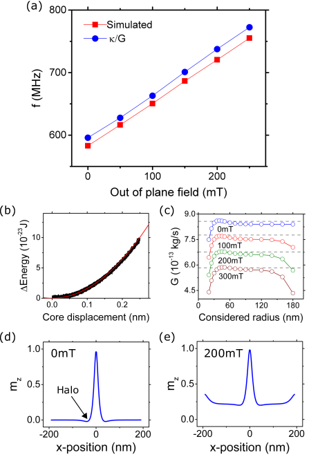
We will first consider the case of a vortex in a spatially uniform out-of-plane field de Loubens et al. (2009), . Fig. 1(a) shows the simulated gyrotropic frequency under various amplitude out-of-plane fields aligned with the vortex core. As previously observed, the frequency varies linearly with . We were able to quantitatively reproduce the simulated frequencies to within 2% [blue circles in Fig. 1(a)] using Guslienko et al. (2002)
| (1) |
where is the vortex stiffness coefficient and is the gyroconstant. The remainder of this section is focused on the extraction of and to obtain the calculated values shown in Fig. 1(a).
, the stiffness coefficient describes the harmonic scaling of the vortex energy, , with lateral in-plane displacement, , measured radially from the disk’s center: . For uniform or null out-of-plane fields, this confinement is dominated by dipolar effectsGuslienko et al. (2006) however dynamic exchange fields are also present. For each simulation, we extracted from a parabolic fit to the total energy of the system plotted against the dynamic displacement of the core as measured during the field-pulse-induced gyrotropic motion [e.g. Fig. 1(b)]. As shown previouslyBuchanan et al. (2006), this dynamic approach, which analyzes the energy of the moving vortex core, produces a more accurate prediction of the gyrotropic frequency than a static method in which the total energy is calculated for displaced cores at equilibrium which have been shifted by static in-plane fields. This said, the static method will be instructive in visualizing the influence of localized fields on the vortex stiffness.
The gyroconstant, , determines the magnitude of the gyrovector, , in the Thiele equation describing vortex dynamics Thiele (1973); Huber (1982); Guslienko et al. (2002); Ivanov and Zaspel (2007). The gyroconstant can be calculated from the vortex spin structure using
| (2) |
where is the gyromagnetic ratio and is the unit-length magnetization vector. Given that acts along the z-axis this equation can be shown to be equal to the often quoted Guslienko et al. (2002); Huber (1982) where and are the polar and azimuthal angles of the magnetization respectively. Theoretically, for a zero out-of-plane field Eq. (3) yields where is the vorticity and is the core polarity aligned along .
We numerically calculated the gyroconstant associated with the static, non-displaced core for the studied values using Eq. (3) by integrating a thickness-averaged 222We observed a 0.4% change in G across different layers of the disk. over the entire disk area. However, inserting this calculated value of into Eq. (1) led to a value for which was significantly lower than the simulated value. For example, for a uniform out-of-plane field of 200 mT the gyroconstant calculated using this method is smaller than what is expected taking the simulated frequency and extracted and solving for (i.e. kgs-1 compared to kgs). To attempt to understand this discrepancy, we calculated by considering only the spin structure within a given radius of the disk center for four different values. The resultant data is shown in Fig. 1(c). reaches a clear maximum when integrating over a radius close to the edge of the vortex core ( nm). Notably, at this point, the value of closely corresponds to the gyroconstant expected from the simulated frequency and extracted stiffness coefficient. This peak is present for all out-of-plane field amplitudes and is due to the ‘magnetostatic halo’ [see Fig. 1(d)] surrounding the vortex core as a result of its demagnetization field Gaididei et al. (2010). The drop-off in at large radii for is due to the out-of-plane canting of spins near the disk edge [e.g. Fig. 1(e)]. Encouragingly, the calculated using this method corresponds closely to the value predicted by the equation given by de Loubens et al de Loubens et al. (2009) for uniform out-of-plane fields where is given as the polar angle of the magnetization at the disk’s edge. The value of calculated using the above expression for is shown by the gray dashed lines in Fig. 1(c) however has been extracted at the center of the magnetostatic halo. This result suggests that although there is a divergence of the magnetization far away from the vortex core, it is the local spin structure around the core which is relevant for the small amplitude oscillations considered here ( nm).
In Fig. 1(c) we see that reduces considerably when is increased and it is this reduction in which is primarily responsible for the linear increase in with increasing . In fact, is reduced at large values where it becomes easier to shift the vortex laterally. Below, localized out-of-plane fields will also be shown to increase however that increase will be demonstrated to be primarily due to a increase in induced by the localized field.
IV Effect of spatially localized fields
IV.1 Gaussian fields
To study the effect of spatially localized out-of-plane fields on the gyrotropic frequency, we first consider centralized fields with a two-dimensional (2D) Gaussian-like profile:
| (3) |
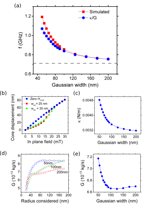
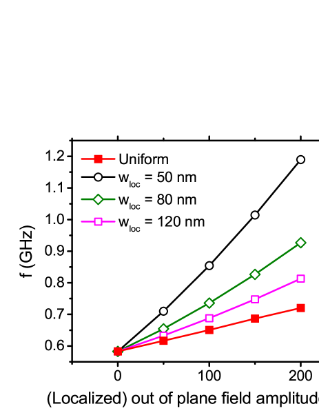
Here is a width parameter approximately equal to 1.2 times the half-width-half-maximum (HWHM) of the field profile and is the lateral distance from the center of the disk. is fixed at +200 mT making aligned with the vortex polarity (). As shown in Fig. 2(a) localized Gaussian fields significantly increase as compared to the action of a spatially uniform 200 mT out-of-plane field [gray dotted line in Fig. 2(a)]. Furthermore, this frequency enhancement becomes larger as the Gaussian field becomes more localized.
To begin to understand the above frequency behavior (and confirm its link it to a -induced confinement), we first look at how the vortex core moves laterally in response to static, uniform in-plane fields, , in the presence of a centrally localized field, . By doing this we can explicitly probe the (static) confinement of the core across the disc. In the complete absence of an out-of-plane field, the core position varies linearly with at low fields (low displacements) [Fig. 2(b)]. For higher displacements the response to field is slightly weaker, consistent with an increased (anharmonic Sukhostavets et al. (2013)) confinement when the core moves closer to the disk’s edge under the action of . If we add a localized field however, the -induced core displacement is clearly lower, but only if the displacement is comparable or smaller than the HWHM of the localized field. Indeed, at larger displacements, the response to is similar for both localized and uniform out-of-plane fields. This result explicitly confirms the -induced confinement (or stiffening) of the vortex core which arises because keeping the core within the central region minimizes the Zeeman energy associated with the interaction between and the vortex core magnetization.
The influence of on the -induced shift is visualized directly in Fig. 3 where we compare the equilibrium static positions of the vortex core (white) for mT in two cases: a vortex with no out-of-plane field [Fig. 3(a)] and a vortex subject to a field with nm [Fig. 3(b)]. The core has clearly been displaced a smaller distance for the case of a localized field, with the core remaining within the strong part of the profile (visible as a broad out-of-plane magnetization component at the disk’s center). Reference images of the unshifted vortex core at mT are given in Figs. 3(c,d).
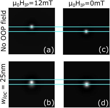
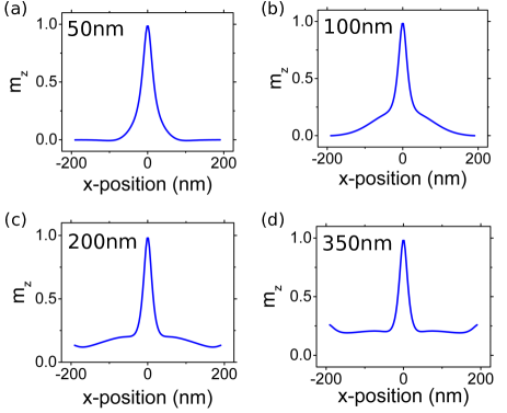
By looking at Fig. 3(d) and Fig. 4, the latter showing profiles of the out-of-plane component of the magnetization across the disk, one also sees that the presence of clearly modifies the magnetic configuration within the disk. For small the equilibrium core structure itself is changed [Fig. 4(a)]: the magnetostatic halo is less sharp and the core widens. Intermediate values [Figs. 4(b,c)] generate a clear out of plane magnetized region around the core while large values [Fig. 4(d)], which lead to a broad field profile, result in a magnetization profile which is similar to that seen for uniform out-of-plane fields [Fig. 1(e)]. For small displacements of the core in all of these cases however, the confining potential nevertheless remains close to harmonic and we have again used the method previously described to calculate (dynamic) values of . Consistent with the results seen in Figs. 2(a,b) and 3, increases strongly for narrower localizations of the Gaussian field [as shown in Fig. 2(c)], again confirming the -induced confinement.
We also calculated the gyroconstant in the presence of the fields, again considering different radii as done previously. The resultant data are shown in Fig. 2(d) for three Gaussian field profiles. Notably, the peak in which was clearly visible in Fig. 1(c) disappears (or for nm becomes much less prominent) due to the absence of a deep magnetostatic halo for the studied values [Fig. 4]. For the two broader Gaussians, increases with the considered radius since the non-uniform induces a canting which depends on the distance from the center of the disk [as seen in Figs. 4(b,c)]. For the narrowest Gaussian, becomes flat at large considered radii. This is because the narrow localization of leads to a quasi-null canting of away from the center. However, grows quickly at small and intermediate considered radii, due to the -induced broadening of the core [Fig. 4(a)]. In Fig. 2(e) we show the extracted values versus where was again calculated using a considered radius of 40 nm (i.e. analyzing the magnetization in the core’s immediate vicinity). Like , also increases at small but to a lesser extent.
The extracted and dynamic yield reasonable quantitative agreement between the simulated frequencies and the frequency predicted by Eq. (1) [red squares in Fig. 2(a)]. This said, the agreement is clearly best at large . This is perhaps not unexpected however since wider profiles result in weaker deformation of the magnetization near the core. We also emphasize that, in contrast to the case of a uniform out-of-plane field the growth in at small [Fig. 2(a)] is driven by increased confinement [i.e. in Fig. 2(c)] rather than by changes in [Fig. 2(e)].
Up until now we have considered only the modifications to induced by changing . Fig. 5 however shows data analogous to that in Fig. 1(a), demonstrating the change in induced when modifying the amplitude of the localized fields. The change to per unit of field amplitude, which can be thought of as a ‘field sensitivity’, is notably more than five times larger for a localized Gaussian field with nm than that observed for a spatially uniform field. Consistent with the results shown in Fig. 2(a), this sensitivity enhancement reduces as the field profile is made broader (i.e. when increases).
Finally for this section, we demonstrate that the trends observed in Fig. 2(a) apply to other disk geometries333Other disk geometries were simulated using a cell size of nm3.. Fig. 6(a) shows the frequency increase (relative to under mT) as a function of for three different disk radii. The increase in is found to be almost independent of the disk radius. This demonstrates for these radii that the frequency increase (at least for small oscillations in the presence of this strong 200 mT localized field) is largely independent of the ‘intrinsic’ core confinement which is defined by the disc geometry. The increase instead results from the interaction between the localized field and the vortex core, the size of the latter being independent of the lateral disk dimensions Usov and Peschany (1993). Along these same lines, since is intrinsically smaller at larger disk radiiGuslienko et al. (2002); Park and Crowell (2005); Guslienko et al. (2006); de Loubens et al. (2009) due to a weaker core confinement, the relative frequency shift induced by a localized field (i.e. as a percentage) will be higher for wider disks [see Fig. 6(b)].
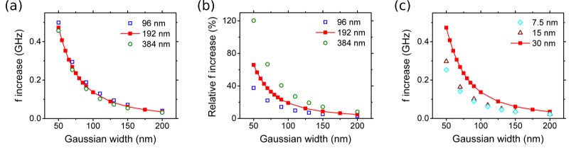
Analogous behavior to that shown in Fig. 2(a) was also seen when reducing the disk thickness. The absolute change in did however reduce as the disk became thinner [Fig. 6(c)]. This reduction was found to be driven by a reduced dynamic (confirmed at nm), indicating a lower Gaussian-field-induced core confinement at smaller thicknesses. This reduced confinement is perhaps not surprising as decreasing the disk thickness leads to a smaller vortex core volume (the core is narrower Usov and Peschany (1993) and its height reduces), lowering the -associated Zeeman energy which drives the confinement.
IV.2 Dipole fields and width-dependent Gaussian fields
Localized magnetic fields can also be generated by uniformly magnetized, spherical MNPs. The in-plane components of the field generated by a submicron particle has previously been used to shift the vortex core position and probe the anharmonicity of the disk’s intrinsic confining potentialSukhostavets et al. (2013). Here we consider the case of a field generated by a centralized MNP with radius whose lower surface is at a fixed distance (10 nm) from the upper surface of the disk (i.e. the height of the center of the MNP from the top of the disk will be nm). To minimize simulation time the field created by a MNP with saturation magnetization has been modelled as that of a dipole with moment where kAm-1. To confirm the validity of this simplification, we determined the gyrotropic frequency observed when a solid ferromagnetic sphere of diameter 100 nm ( pJ/m) was placed above the center of the disk (in this case we used a smaller disk with nm to minimize simulation time and memory use) and explicitly simulated it together with the disk in a 200 mT uniform out-of-plane field. When compared to the simulated in an equivalent dipole field there was a relatively small discrepancy of which was further reduced to 0.3% when adding a strong -axis oriented anisotropy to the sphere ( J/m3). The latter tends to fix the sphere’s magnetization in the out-of-plane orientation, suggesting that the worse agreement for the zero-anisotropy sphere was due to changes in the sphere’s magnetic configuration induced by the magnetic stray field of the disk. We also note that the simulations below were performed with no external out-of-plane field. However, a field would usually have to be applied experimentally in the case of a superparamagnetic particle and indeed we found analogous results to those given below [ versus in Fig. 7(a)] for simulations in a 200 mT external out-of-plane field (sufficient to induce the aforementioned valueMetaxas et al. (2015)).
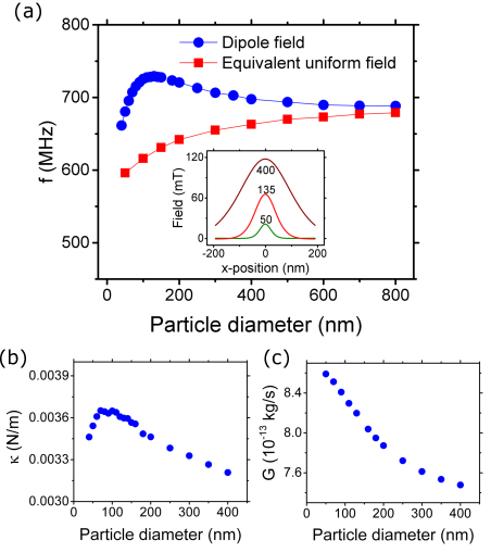
In Fig. 7(a), we show results obtained for dipoles equivalent to -magnetized MNPs of various sizes positioned above the disk as detailed above. In contrast to the case of the Gaussian field, displays a maximum at some intermediate particle size. This behavior cannot be explained simply by the stray field changing in magnitude as changes. Indeed, if we run simulations to determine in the presence of uniform out-of-plane fields equivalent in magnitude to the MNP field (as calculated in the center of the disk) we see a monotonically increasing [red squares in Fig. 7(a)] with no peak. This latter growth in is consistent with the bigger particles generating bigger fields and thus bigger changes in [i.e. as per Fig. 1(a)]. Instead, the peak in observed for the dipole fields at intermediate can be correlated with a maximum in the confinement of the core, manifested as a peak in [Fig. 7(b)]. Note however that the maximum occurs at a slightly higher diameter than that which leads to the maximum due to the diameter dependence of which increases [thus reducing , as per Eq. (1)] as the particle diameter becomes small [Fig. 7(c)].
In the inset of Fig. 7(a) we show the out-of-plane component of the dipolar MNP field for particle diameters located around the point at which the peak in lies. The peak in confinement can be understood as follows. At small particle diameters (e.g. nm), the field is highly localized however the magnetic moment of the MNP (and thus the stray field amplitude) is low. This results in a weak confinement. A weak confinement also occurs for large particles (e.g. nm) which generate strong but nevertheless broad (and thus weakly localized) spatial field profiles. Between these two extrema however is some intermediate particle size (e.g. nm) where there is an optimal combination of field strength and localization which maximizes the core confinement, thus leading to a large .
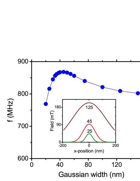
We can also reproduce the above tendencies using Gaussian fields which have been scaled by a factor . This scaling mimics some characteristics of the -dependent dipole field. is chosen to be 25 nm as this is the distance used in our simulations between the bottom of the particle and center of the disk. The numerator in the above scaling factor describes the magnetic moment dependence on particle radius (here equivalent to ) whereas the denominator describes the field behavior as the dipole center moves further away from the disk center due to an increasing particle radius. The simulated values are shown in Fig. 8. Unlike the results for Gaussian fields of constant amplitude, now exhibits a peak at intermediate values, analogous to the frequency behavior seen for MNPs when changing [Fig. 7(a)]. The corresponding one dimensional Gaussian field profiles are shown in the inset of Fig. 8 for three different values. Again, as we increase we see a transition from a weak, highly localized field to a strong, broadly localized field with maximum confinement occurring at an intermediate .
V Conclusion
We have shown that the sensitivity of the vortex gyrotropic mode frequency to out-of-plane fields can depend strongly on the spatial localization of those fields. Centralized, out-of-plane magnetic fields localized over lengths which are comparable to or a few times larger than the vortex core radius induce significantly larger changes in the vortex gyrotropic frequency than that generated by a spatially uniform out-of-plane field of the same amplitude. This behavior is consistent with an increase in the vortex stiffness as a result of the out-of-plane magnetization of the core preferentially aligning with the strongest part of the localized field which generates an additional vortex core confinement. In the case of fields which approximate those generated by magnetic particles of varying radius, the frequency was observed to be maximized for some intermediate particle size which led to an optimized combination of field amplitude and field localization. This may be relevant for vortex-based MNP sensors exploiting changes of the gyrotropic frequency induced by localized MNP fieldsWohlhüter et al. (2015). We finally note that this work has focused on very low amplitude excitations and highlight the fact that gyrotropic motion outside of the strongest part of the localized field will result in weaker changes to (as observed by Min et al.Min et al. (2011) for large amplitude oscillations around pinning sites generated by changes in saturation magnetization).
Acknowledgements.
This work was supported by the Australian Research Council’s Discovery Early Career Researcher Award scheme (DE120100155), a research grant from the United States Air Force (Asian Office of Aerospace Research and Development, AOARD), the University of Western Australia (including the ECRFS, RCA and RDA schemes), NeCTAR (National eResearch Collaboration Tools and Resources, supported by the Australian Government through the National Collaborative Research Infrastructure Strategy) and by resources provided by the Pawsey Supercomputing Centre with funding from the Australian Government and the Government of Western Australia. The authors thank Joo-Von Kim, Manu Sushruth, Mikhail Kostylev, Vincent Cros, Rebecca Carey, Maximilian Albert and Hans Fangohr for useful discussions, advice and/or assistance.References
- Shinjo et al. (2000) T. Shinjo, T. Okuno, R. Hassdorf, K. Shigeto, and T. Ono, Science 289, 930 (2000).
- Wachowiak et al. (2002) A. Wachowiak, J. Wiebe, M. Bode, O. Pietzsch, M. Morgenstern, and R. Wiesendanger, Science 298, 577 (2002).
- Guslienko (2008) K. Y. Guslienko, J. Nanosci. Nanotech. 8, 2745 (2008).
- Cowburn et al. (1999) R. P. Cowburn, J. Ferré, S. J. Gray, and J. A. C. Bland, J. Appl. Phys. 74, 1466 (1999).
- Vogel et al. (2011) A. Vogel, T. Kamionka, M. Martens, A. Drews, K. W. Chou, T. Tyliszczak, H. Stoll, B. Van Waeyenberge, and G. Meier, Phys. Rev. Lett. 106, 137201 (2011).
- Yakata et al. (2013) S. Yakata, T. Tanaka, K. Kiseki, K. Matsuyama, and T. Kimura, Sci. Rep. 3, 3567 (2013).
- Pribiag et al. (2007) V. S. Pribiag, I. N. Krivorotov, G. D. Fuchs, P. M. Braganca, O. Ozatay, J. C. Sankey, D. C. Ralph, and R. A. Buhrman, Nat. Phys. 3, 498 (2007).
- Dussaux et al. (2010) A. Dussaux, B. Georges, J. Grollier, V. Cros, A. V. Khvalkovskiy, A. Fukushima, M. Konoto, H. Kubota, K. Yakushiji, S. Yuasa, K. A. Zvezdin, K. Ando, and A. Fert, Nat. Commun. 1, 8 (2010).
- Jenkins et al. (2015) A. S. Jenkins, R. Lebrun, E. Grimaldi, S. Tsunegi, P. Bortolotti, H. Kubota, K. Yakushiji, A. Fukushima, G. de Loubens, O. Klein, S. Yuasa, and V. Cros, arXiv:1505.05358 , 2262 (2015).
- Kim et al. (2010) D. Kim, E. Rozhkova, I. Ulasov, S. Bader, T. Rajh, M. Lesniak, and V. Novosad, Nat. Mater. 9, 165 (2010).
- Yamada et al. (2007) K. Yamada, S. Kasai, Y. Nakatani, K. Kobayashi, H. Kohno, A. Thiaville, and T. Ono, Nat. Mater. 6, 270 (2007).
- Huber and Grundler (2011) R. Huber and D. Grundler, Proc. SPIE 8100, 81000D (2011).
- Han et al. (2013) D.-S. Han, A. Vogel, H. Jung, K.-S. Lee, M. Weigand, H. Stoll, G. Schᅢᄐtz, P. Fischer, G. Meier, and S.-K. Kim, Sci. Rep. 3, 2262 (2013).
- Behncke et al. (2015) C. Behncke, M. Hänze, C. F. Adolff, M. Weigand, and G. Meier, Phys. Rev. B 91, 224417 (2015).
- Guslienko et al. (2002) K. Y. Guslienko, B. A. Ivanov, V. Novosad, Y. Otani, H. Shima, and K. Fukamichi, J. Appl. Phys. 91, 8037 (2002).
- Choe et al. (2004) S.-B. Choe, Y. Acremann, A. Scholl, A. Bauer, A. Doran, J. Stöhr, and H. A. Padmore, Science 304, 420 (2004).
- Ivanov (2004) B. A. Ivanov, J. Appl. Phys. 95, 7444 (2004).
- Guslienko et al. (2006) K. Y. Guslienko, X. F. Han, D. J. Keavney, R. Divan, and S. D. Bader, Phys. Rev. Lett. 96, 067205 (2006).
- de Loubens et al. (2009) G. de Loubens, A. Riegler, B. Pigeau, F. Lochner, F. Boust, K. Y. Guslienko, H. Hurdequint, L. W. Molenkamp, G. Schmidt, A. N. Slavin, V. S. Tiberkevich, N. Vukadinovic, and O. Klein, Phys. Rev. Lett. 102, 177602 (2009).
- Locatelli et al. (2011) N. Locatelli, V. V. Naletov, J. Grollier, G. de Loubens, V. Cros, C. Deranlot, C. Ulysse, G. Faini, O. Klein, and A. Fert, Appl. Phys. Lett. 98, 062501 (2011).
- Buchanan et al. (2006) K. S. Buchanan, P. E. Roy, M. Grimsditch, F. Y. Fradin, K. Y. Guslienko, S. D. Bader, and V. Novosad, Phys. Rev. B 74, 064404 (2006).
- Kim (2012) J.-V. Kim, Solid State Phys. Solid State Phys., 63, 217 (2012).
- Lebrun et al. (2014) R. Lebrun, N. Locatelli, S. Tsunegi, J. Grollier, V. Cros, F. Abreu Araujo, H. Kubota, K. Yakushiji, A. Fukushima, and S. Yuasa, Phys. Rev. App. 2, 061001 (2014).
- Braganca et al. (2010) P. M. Braganca, B. A. Gurney, B. A. Wilson, J. A. Katine, S. Maat, and J. R. Childress, Nanotechnol. 21, 235202 (2010).
- Ryan et al. (2011) R. J. Ryan, H. Xi, and I. Jin, Patent US8053244 B2 (2011).
- Srimani et al. (2015) T. Srimani, A. N. Mukhopadhyay, K. Roy, and M. Sharad, arXiv:1511.09072 (2015).
- Mizushima et al. (2010) K. Mizushima, K. Kudo, T. Nagasawa, and R. Sato, J. Appl. Phys. 107, 063904 (2010).
- Inoue et al. (2011) M. Inoue, A. Baryshev, H. Takagi, P. B. Lim, K. Hatafuku, J. Noda, and K. Togo, Appl. Phys. Lett. 98, 132511 (2011).
- Atalay et al. (2015) S. Atalay, A. O. Kaya, V. S. Kolat, H. Gencer, and T. Izgi, J. Supercond. Nov. Magn. 28, 2071 (2015).
- Metaxas et al. (2015) P. J. Metaxas, M. Sushruth, R. Begley, J. Ding, R. C. Woodward, I. Maksymov, M. Albert, W. Wang, H. Fangohr, A. Adeyeye, and M. Kostylev, Appl. Phys. Lett. 106, 232406 (2015).
- Gaster et al. (2009) R. S. Gaster, D. A. Hall, C. H. Nielsen, S. J. Osterfeld, H. Yu, K. E. Mach, R. J. Wilson, B. Murmann, J. C. Liao, S. S. Gambhir, et al., Nat. Med. 15, 1327 (2009).
- Heldt et al. (2014) G. Heldt, M. T. Bryan, G. Hrkac, S. E. Stevenson, R. V. Chopdekar, J. Raabe, T. Thomson, and L. J. Heyderman, Appl. Phys. Lett. 104, 182401 (2014).
- Uhlig et al. (2005) T. Uhlig, M. Rahm, C. Dietrich, R. Höllinger, M. Heumann, D. Weiss, and J. Zweck, Phys. Rev. Lett. 95, 237205 (2005).
- Zarzuela et al. (2012) R. Zarzuela, S. Vélez, J. M. Hernandez, J. Tejada, and V. Novosad, Phys. Rev. B 85, 180401(R) (2012).
- Zarzuela et al. (2013) R. Zarzuela, E. M. Chudnovsky, J. M. Hernandez, and J. Tejada, Phys. Rev. B 87, 144420 (2013).
- Silva et al. (2008) R. L. Silva, A. R. Pereira, R. C. Silva, W. A. Moura-Melo, N. M. Oliveira-Neto, S. A. Leonel, and P. Z. Coura, Phys. Rev. B 78, 054423 (2008).
- Vansteenkiste et al. (2009) A. Vansteenkiste, M. Weigand, M. Curcic, H. Stoll, G. Schütz, and B. Van Waeyenberge, New J. Phys. 11, 063006 (2009).
- Compton et al. (2010) R. L. Compton, T. Y. Chen, and P. A. Crowell, Phys. Rev. B 81, 144412 (2010).
- Min et al. (2011) H. Min, R. D. McMichael, J. Miltat, and M. D. Stiles, Phys. Rev. B 83, 064411 (2011).
- Chen et al. (2012) T. Y. Chen, M. J. Erickson, P. A. Crowell, and C. Leighton, Phys. Rev. Lett. 109, 097202 (2012).
- Vansteenkiste et al. (2014) A. Vansteenkiste, J. Leliaert, M. Dvornik, M. Helsen, F. Garcia-Sanchez, and B. Van Waeyenberg, AIP Adv. 4, 107133 (2014).
- Ivanov and Zaspel (2002) B. A. Ivanov and C. E. Zaspel, Appl. Phys. Lett. 81, 1261 (2002).
- Ivanov and Zaspel (2005) B. A. Ivanov and C. Zaspel, Phys. Rev. Lett. 94, 027205 (2005).
- Park and Crowell (2005) J. P. Park and P. A. Crowell, Phys. Rev. Lett. 95, 167201 (2005).
- Zaspel et al. (2005) C. E. Zaspel, B. A. Ivanov, J. P. Park, and P. A. Crowell, Phys. Rev. B 72, 024427 (2005).
- Aliev et al. (2009) F. G. Aliev, J. F. Sierra, A. A. Awad, G. N. Kakazei, D.-S. Han, S.-K. Kim, V. Metlushko, B. Ilic, and K. Y. Guslienko, Phys. Rev. B 79, 174433 (2009).
- Donahue and Porter (1999) M. J. Donahue and D. G. Porter, OOMMF User’s Guide, Version 1.0, Interagency Report NISTIR 6376, Tech. Rep. (National Institute of Standards and Technology, Gaithersburg, MD, 1999).
- Fischbacher et al. (2007) T. Fischbacher, M. Franchin, G. Bordignon, and H. Fangohr, IEEE Trans. Mag. 43, 2896 (2007).
- Note (1) Simulations for an identically sized disk ( nm, nm) with a nm3 cell size were run in OOMMF for zero field (agreement with MuMax within 1.1%) and in the presence of a localized field (Sec. IV.1) with nm (agreement within 1%). There was also good agreement in the bare disk frequency using the eigenmode solver in FinMag for a nm disk however a larger meshing had to be used at the disk edges due to memory constraints.
- Thiele (1973) A. Thiele, Phys. Rev. Lett. 30, 230¬タモ233 (1973).
- Huber (1982) D. L. Huber, Phys. Rev. B 26, 3758 (1982).
- Ivanov and Zaspel (2007) B. A. Ivanov and C. E. Zaspel, Phys. Rev. Lett. 99, 247208 (2007).
- Note (2) We observed a 0.4% change in G across different layers of the disk.
- Gaididei et al. (2010) Y. Gaididei, V. P. Kravchuk, and D. D. Sehka, Int. J. Quant. Chem. 110, 83 (2010).
- Sukhostavets et al. (2013) O. V. Sukhostavets, B. Pigeau, S. Sangiao, G. de Loubens, V. V. Naletov, O. Klein, K. Mitsuzuka, S. Andrieu, F. Montaigne, and K. Y. Guslienko, Phys. Rev. Lett. 111, 247601 (2013).
- Note (3) Other disk geometries were simulated using a cell size of nm3.
- Usov and Peschany (1993) N. Usov and S. Peschany, J. Magn. Magn. Mater. 118, L290 (1993).
- Wohlhüter et al. (2015) P. Wohlhüter, M. T. Bryan, P. Warnicke, S. Gliga, S. E. Stevenson, G. Heldt, L. Saharan, A. K. Suszka, C. Moutafis, R. V. Chopdekar, J. Raabe, T. Thomson, G. Hrkac, and L. J. Heyderman, Nat. Comms. 6, 7836 (2015).