Application of a PWFA to an X-ray FEL
Abstract
There is a growing demand for X-ray Free-electron lasers (FELs) in various science fields, in particular for those with short pulses, larger photon fluxes and shorter wavelengths.
The level of X-ray power and the pulse energy depend on the amount of electron bunch energy. Increasing the latter will increase the power of the radiating X-rays.
Using numerical simulations we explore the possibility of using a plasma wakefield accelerator (PWFA) scheme to increase the electron beam energy of an existing FEL facility without significantly increasing the accelerator length. In this paper we use parameters of the SwissFEL beam.
The simulations are carried out in 2D cylindrical symmetry using the code OSIRIS. Initial results show an energy gain of 2 GeV after propagation of 0.5 m in the plasma with a relative energy spread of 1%.
keywords:
Plasma wake Free Electron Laser FEL PWFA1 Introduction
Free Electron Lasers (FELs) provide very intense and tightly focused X-ray beams. These X-rays can be used to map the atomic structure of materials, including bio-molecules and nanometer scale structures. The laser power and the radiation wavelength are determined by the energy and brightness of the electron bunches.
In this paper, we present an FEL scheme which includes a plasma wakefield accelerator (PWFA) after the linear accelerator (linac).
PWFAs can provide accelerating gradients up to 100 GV/m, orders of magnitudes higher than gradients that can be produced by conventional radio frequency linacs. By adding a PWFA after the linac, we may be able to double the electron energy in a much shorter distance than that of the linac and potentially generate a pulse with higher energy and a shorter wavelength.
One of the promising future FELs, SwissFEL, is being constructed by Paul Scherrer Institute (PSI). The beam parameters in this study have been chosen from within the range of possible operating modes of SwissFEL.
2 Swiss FEL Beam Parameters
The SwissFEL baseline design seeks to provide a wavelength range from 0.1 nm to 7 nm. The undulator design, chosen for the minimum wavelength (0.1 nm), has a period length, , of 15 mm and an undulator parameter, , equal to 1.2 [1]. The radiation wavelength is given by
| (1) |
where is the electrons energy in units of the rest energy .
Therefore, for this operation the energy of the electron beam is 5.8 GeV.
The accelerator facility enables different operation modes. The beam charge can typically range between 10 pC and 200 pC and the bunch size (), from 10 m to 20 m. Beams with 200 pC are characterized by normalized projected emittance mm.mrad and a 350 keV energy spread.
The saturation power can be estimated via , with .
is the Pierce parameter, defined as [2]:
| (2) |
where is the electron beam peak current, is Alfven current ( kA) and the Bessel function factor
is equal to .
By increasing the electron beam energy to 13.6 GeV with =30 mm and K=2.75111Using [cm], is the peak magnetic field of the undulator on the axis., we can increase the saturation power by a factor of 2.5. In addition, the lasing requirements: and , where is the local intrinsic energy spread, are better fulfilled with higher beam energies. Using a PWFA might make this energy jump possible within a compact acceleration distance.
3 The PWFA Scheme
A PWFA fires a driving bunch into a plasma and uses the resulting oscillation of plasma electrons to accelerate a witness bunch. An effective acceleration depends on the bunch parameters (charge , longitudinal size and transverse size ) as well as on the plasma density . The most important is the drive bunch longitudinal size, which should be in the same order of the plasma wavelength.
This study focuses on the non-linear regime (or the bubble regime), where the drive bunch density exceeds the plasma density.
In the non-linear regime the transverse wakefield, , inside each bubble is independent of the propagation direction (Figure 1) and linear with the radius [3]. Therefore, the bunch experiences a constant focusing force inside the bubble, minimizing the emittance growth through the propagation.
In addition, within each bubble the longitudinal wakefield, , is independent of the radius and thus equally accelerates particles with the same longitudinal position. However, the accelerating field varies linearly with the longitudinal position, leading to a correlated energy spread for an accelerated witness bunch. By means of simulations we investigate the loading of the wakefield by the witness bunch in order to reduce the final energy spread.

For the PWFA design, we use OSIRIS [4] code to perform numerical simulations with 2D cylindrical symmetry.
Our preliminary PWFA scheme includes a plasma with cm-3 and a 400 pC drive bunch with =20 m and =10 m. The selection of the witness bunch parameters is based on the beam loading principles [5] in order to minimize the energy-spread. In the current design a 170 pC witness bunch with transverse and longitudinal lengths of 10 m is placed 5 from the drive bunch. For simplicity, the bunches are assumed to be mono-energetic with an energy of 5.8 GeV at injection in the plasma. The parameters for this scenario are summarized in Table 1.
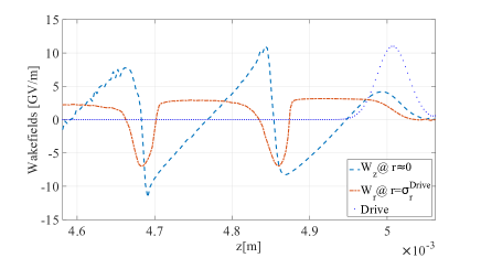
Figure 2 presents the longitudinal and transverse wakefields after propagation of 5 mm of the drive and witness bunches in the plasma . We can see that the accelerating gradient reaches about 3.5 GeV/m and the field is relatively constant in the witness bunch.
From this initial accelerating gradient, we can estimate the average energy gain of the witness bunch after =0.5 m to be 1.75 GeV.
| 3.53 cm-3 | |
| peaks separation | 100 m |
| initial energy | 5.8 GeV |
| m | |
| m | |
| 400 pC | |
| m | |
| m | |
| 170 pC |
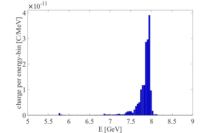
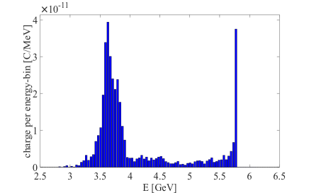
Figure 3 presents the energy distributions of the drive and the witness bunches at 0.5 m. The witness bunch distribution has a maximum value at 7.94 GeV and a full width at half maximum (FWHM) of 80.32 MeV with 57% of the bunch particles. The mean value of the drive bunch is 4.13 GeV and the FWHM is 2.1 GeV. Accordingly, the witness bunch gained GeV while the drive bunch lost GeV. The relative energy spread of the witness bunch is about 1%, yet does not satisfy the SwissFEL requirements.
4 Conclusions
FEL saturation power depends on the energy of the electron bunches. In the case of SwissFEL, reaching an energy level of 13.6 GeV will increase the power by a factor of 2.5. A PWFA scheme with SwissFEL bunch parameters and cm-3 can reach an accelerated field with a multi GeV/m scale. In this first study we show an energy gain of GeV in 0.5 m for the witness bunch. Consequently, we can assume a doubling of the beam energy in very few meters.
We loaded the plasma wave and minimized the energy spread of the witness bunch to 80.3 MeV. However SwissFEL operation requires an energy spread of 350 keV. An useful approach would be to investigate particles with an energy range of 175 keV around the maximum distribution value. This would insure a suitable energy spread, while reducing the applicable charge for lasing.
We note here that loading of the longitudinal field leads to a modification of the transverse field in the witness bunch as can be seen in Figure 2. Future studies will aim at reducing the witness bunch energy spread as well as at minimizing potential emittance growth due to ”loading” of the transverse wakefields.
5 Acknowledgment
The authors would like to acknowledge the OSIRIS Consortium, consisting of UCLA and IST (Lisbon, Portugal) for the use of OSIRIS, for providing access to the OSIRIS framework.
References
- [1] Paul Scherrer Institute. SwissFEL CDR. 2012.
- [2] Z. Huang and K. J. Kim. Review of x-ray free-electron laser theory. Physical Review Special Topics - Accelerators and Beams, 10, 2007.
- [3] J. B. Rosenzweig et al. Acceleration and focusing of electrons in two-dimensional nonlinear plasma wake fields. Phys.Rev.A., 44, R6189(R), 1991.
- [4] R. A. Fonseca et al. Osiris: A three-dimensional, fully relativistic particle in cell code for modeling plasma based accelerators. Lecture Notes in Computer Science, 2331:342–351, 2002.
- [5] M. Tzoufras et al. Beam loading in the nonlinear regime of plasma-based acceleration. Phys.Rev.Lett., 101, 145002, 2008.