Improving Bandwidth Efficiency of FBMC-OQAM Through Virtual Symbols
Abstract
Filter bank multicarrier (FBMC) systems that are based on offset quadrature amplitude modulation (OQAM), namely, FBMC-OQAM, have been criticized for their inefficiency in the use of spectral resources, because of the long ramp-up and ramp-down tails at the beginning and the end of each data packet, respectively. We propose a novel method for shortening these tails. By appending a set of virtual (i.e., none data carrying) symbols to the beginning and the end of each packet, and clever selection of these symbols, we show that the ramp-up and ramp-down tails in FMBC-OQAM can be suppressed to an extent that they deem as negligible and thus may be ignored. This shortens the length of signal burst in each FBMC-OQAM packet, hence, improves on its bandwidth efficiency, viz., the same data is transmitted over a shorter period of time. We develop an optimization method that allows computation of virtual symbols, for each data packet. Simulation results show that, compared to existing methods, the proposed tail-shortening approach leads to a superior out-of-band (OOB) emission performance and a much lower error vector magnitude (EVM) for the demodulated symbols.
Index Terms:
virtual symbols, FBMC-OQAM, EVM, spectral efficiency.I Introduction
In the past, orthogonal frequency division multiplexing (OFDM) has enjoyed its dominance as the most popular signaling method for broadband communications, [1], [2]. Most of the broadband standards, as of today, have adopted OFDM. OFDM offers a minimum complexity, achieves a fair bandwidth efficiency, and possibly is the best compromise choice for point-to-point communication. However, it has been noted that OFDM has to face many challenges when considered for adoption in the more complex networks. For instance, the use of OFDM in the uplink of multiuser networks, known as OFDMA (orthogonal frequency division multiple access), requires accurate synchronization of the users’ signals at the base station input, [3]. Such synchronization is not straightforward and demands a lot of resources.
Taking note of these issues, currently, many researcher are exploring alternative waveforms for the next generation of wireless communications; the 5G. Researchers in the Alcatel-Lucent Bell Laboratories have proposed and studied a modified OFDM waveform that they call universal filtered multicarrier (UFMC), [4, 5, 6, 7, 8]. In UFMC, each bundle of adjacent subcarriers that belong to a user are passed through a filter to minimize multi-user interference, equivalently, multiple access interference (MAI). To allow good filtering, while its bandwidth efficiency is kept at the same level as OFDM, in UFMC, there is no cyclic prefix (CP) and, instead, the CP interval is reserved to absorb the transient of the underlying filters.
Generalize frequency division multiplexing (GFDM) is another popular waveform that has been proposed by Fettweis et al., [9, 10]. GFDM may be thought of as a modified OFDM waveform, where each subcarrier is shaped by a high quality filter. Moreover, to keep the spectral efficiency high, GFDM is designed such that one CP is added to a block of data symbols that are spread across subcarriers and time slots. Also, to allow the addition of CP, the subcarriers filtering operation in GFDM is based on a circular convolution (not a linear convolution).
The third contender for 5G builds its waveform based on filter bank multicarrier with offset quadrature amplitude modulation (FBMC-OQAM) at the same time filtering operations are based on circular convolution, as in GFDM, [11, 12, 13, 14]. It is thus named cyclic FBMC (C-FBMC). Also, similar to GFDM, a CP is added to each block of data symbols. In this paper, for brevity, we remove the suffix OQAM from FBMC. Hence, any mention of FBMC should be understood as being FBMC with OQAM signaling.
The presence of CP in GFDM and C-FBMC allows multi-users in the uplink of a network to be quasi-synchronous, hence, perfect synchronization can be relaxed. In UFMC, this relaxed synchronization is allowed because of the presence of soft ramp-up and ramp-down at the two sides of each symbol. However, one should note that still GFDM, C-FBMC, and UFMC require synchronization of the mobile nodes to a great degree.
Literatures on UFMC, GFDM, and C-FBMC, beside reviewing the shortcomings of OFDM for 5G, have also criticized the conventional FBMC, [15, 16, 17, 18, 19, 20, 21], where filtering is based on linear convolution. It has been noted that such waveform are bandwidth inefficient because of the signal ramp-up and ramp-down (arising from filtering transients) at the beginning and the end of each data packet, respectively. However, we note that FBMC has an advantage over UFMC, GFDM, and C-FBMC as users can be completely asynchronous. Taking note of this important property of FBMC, this paper revisits FBMC with the goal of redesigning the waveform such that it will have very short ramp-up and ramp-down, hence, bringing FBMC bandwidth efficiency to a level comparable to those of UFMC, GFDM, and C-FBMC.
Another point that needs our attention here is the following. In GFDM and C-FBMC literature, it has often been emphasized that each data packet makes use of only one CP, and thus argued that these waveforms offer a very high bandwidth efficiency. This may not remain true in some practical cases, where long packets of data have to be transmitted and hence channel variation over each packet interval may not remain negligible. In such cases, each packet should be divided into a number of shorter blocks and GFDM/C-FBMC waveform synthesis, including addition of CP, is applied to each block. Pilot symbols are also added into each block to assist the receiver in tracking channel variations, following the methods that have been developed for OFDM, [22]. Noting this and the fact that FBMC packets for any size have only one ramp-up and one ramp-down implies that FBMC for long packets offers a higher bandwidth efficiency than GFDM, C-FBMC, and UFMC.
In the past, couple of trivial methods have been proposed to reduce ramp-up and ramp-down durations in FBMC. These methods have been referred to by the generic name of tail-shortening. The first tail-shortening approach aplies a hard truncation to the signal tails, [23]. Although this method totally removes the tail, the truncation causes intersymbol interference (ISI) as well as intercarrier interference (ICI) on the data symbols near the edges of the data packet. In addition, it increases the out-of-band (OOB) emission due to sharp truncation of the signal. An improved method, [24], uses a generalized weighting window to smoothen the edge transitions introduced by truncation. This improves the OOB emission performance, however, it introduces more ISI/ICI than the hard truncation method.
In this paper, we propose a more intelligent method that avoids ISI/ICI and keeps OOB emission similar to that of the FBMC without tail-shortening. We introduce additional, but redundant, symbols at the two sides of the packet and these symbols are chosen such that to suppress the waveform tails without introducing any ISI/ICI and without increasing OOB emission. Since these symbols do not carry any data, we refer to them as virtual symbols.
The rest of this paper is organized as follows. Section II presents a brief description of FBMC-OQAM signaling method. Section III gives a review of the tail truncation methods in the past literature. The proposed tail-shortening method by virtual symbols is presented in Section IV. A few considerations related to the receiver implementation are discussed in Section V. The performance of the proposed method is compared with other tail-shortening methods through computer simulations in Section VI. The concluding remarks are made in Section VII.
II FBMC-OQAM System Model
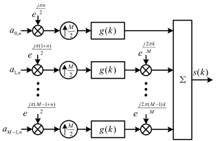
The discrete time domain model of an FBMC-OQAM transmitter is shown in Fig. 1. The subcarrier spacing is , where is the time interval between QAM symbols. Each complex-valued symbol is partitioned into a pair of real-valued/pulse amplitude modulated (PAM) symbols. The PAM symbol at the time-frequency index is denoted by , where is the frequency index and is the time index. Moreover, and are the real and imaginary parts of the -th OQAM symbol, respectively. They are spaced. We assume that there are samples per each symbol interval.
Assuming that is a burst of length of PAM symbols, following Fig. 1, one finds that
| (1) |
where is the set of active subcarriers and is the impulse response of the prototype filter. The prototype filter has a length of , where is the overlapping factor (i.e., the number of FBMC symbols that overlap in time). Accordingly, the burst length is equal to .
III Review of Tail-Shortening Methods
Since FBMC-OQAM systems adopt filters with rather long length, the resulting ramp-up at the beginning and ramp-down at the end of each data burst cover multiple symbol intervals. This considerably reduces the gain of FBMC-OQAM in spectral efficiency, when data bursts are short. In what follows, we use the tail at the end of the burst to illustrate the tail-shortening methods. The processing at the start of the burst is similar.
The most trivial method of shortening the bust length is hard truncation of the tails. For the end part of the burst, this is expressed as
| (2) |
where is the end of the data burst after truncation, and subscript “h.trunc” on is to emphasize it is hard truncated. The cost of this method is an increased OOB emission and ISI/ICI due to the truncation.
Another method, called truncation with windowing, uses a generalized weighting window to shorten the tail. The windowed signal is given as
| (3) |
where is the window function. Specifically, we consider a raised-cosine window, which is expressed as
| (4) |
where is the length of roll-off and is the beginning of the roll-off. Although this method smoothens the edge transitions introduced by truncation, hence, reduces the OOB emission, it results is a greater ISI/ICI than the hard truncation method. This is because the roll-off introduces an additional distortion to the signal.
Furthermore, as discussed earlier, the rump-up and ramp-down issue may be resolved by replacing the linear convolution in FBMC by a circular one and use a CP to take care of channel transient. This leads to C-FBMC signaling, [11, 12, 13, 14]. In addition, to avoid OOB emission caused by hard truncations at the beginning and end of each bust, a soft truncation with windowing, similar to (3), may also be applied. Such windowing to be as effective as FBMC, particularly for frequency points near the passband edges of transmission can increase the length of C-FBMC to that of FBMC (with linear convolution).
IV Tail-Shortening by Virtual Symbols
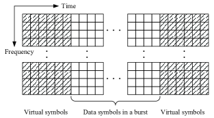
In this paper, we propose adding a few dummy symbols at the two sides of each data burst, as demonstrated in Fig. 2, to suppress the tails of . After suppressing the tails, the residual tails may be truncated with a minimum effect on OOB and/or ISI/ICI interference. Alternatively, the suppressed tails may be allowed to overlap among successive data packets. Such overlap, as our numerical results show, introduces a negligible level of interference.
We refer to the dummy symbols as virtual symbols. One may think of virtual symbols as a means of generating a cancellation signal at the tails of each FBMC burst, hence, removing the tails of the bursts. Moreover, since this signal is synthesized following the FBMC-OQAM construction, it suppresses the tails without introducing any OOB emission as well as no ISI/ICI.
Let , with the elements of , denote the matrix of virtual symbols at the end of the burst. This results in the cancelation signal
| (5) |
where is the number of virtual symbols along the time. With the addition of , we get the tail-shortened/suppressed signal
| (6) |
where ‘vs’ in the subscript is to emphasize that virtual symbols are used for tail-shortening.
To find the virtual symbols, i.e., the elements of , we define the cost functions
| (7) |
and
| (8) |
and search for a choice of that minimizes and jointly. Minimization of suppresses the tail of the burst, beyond . Minimization of , on the other hand, is to assure that the total energy of over the range of is kept minimal. This is necessary to avoid an unexpected increase of over this range, hence, avoid an undesirable increase of peak-to-average power ratio (PAPR) of the burst.
To obtain a balanced minimization and , we find that minimizes the combined cost function
| (9) |
where is a positive parameter that should be found empirically. To derive a convenient formulation for this minimization problem, we proceed as follows.
We define the pair of column vectors and consisting of elements and , respectively. We also note that and can be expanded as
| (10) |
and
| (11) |
where contains samples of , for , is constructed by rearranging the columns of in a column vector, and the matrices and are obtained trivially by taking note of the relationship (5).
Using (10) and (11) in (7) and (12), respectively, and the results in (9), we obtain
| (12) |
Next, noting that is real-valued, but , , and are complex-valued, one may rearrange (12) as
| (13) |
where
and denote the real and imaginary parts, respectively, and indicate a zero column vector.
Minimization of is a least squares problem. It has the solution
| (14) |
where
| (15) |
We also note that is a fixed matrix that depends on the prototype filter and parameters , and . The matrix thus can be pre-calculated and used in (14) to find for each data packet.
Energy of beyond will be very small, after canceling the tail, if and are selected properly. However, the tail will not be exactly zero due to the balance that we are making between the two objectives (10) and (11). Regarding the residual tail, either one of the following two approaches could be applied: (1) Truncate the residual tail beyond . This could raise the out-of-band spectrum and incur interference to the edge data symbols. (2) Keep the residual tail and allow overlapping of the successive packets. Such overlap, clearly, leads to inter-packet interference. However, our numerical study reveals that such interference, when the design parameters are selected correctly, remains negligible.
V Receiver Design Considerations with The Proposed Tail-Shortening
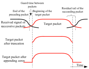
Successive packets with the proposed tail-shortening are allowed to be placed much closer in time than those without tail-shortening. Therefore, receiver with tail-shortening has to be carefully designed to avoid interference from adjacent packets. Such a receiver could work as shown by Fig. 3. First, the receiver detects the beginning and end of the target packet, say, and . This could be accomplished by timing synchronization mechanism of the FBMC system, which relies on the pilot/preamble symbols. Secondly, the receiver extracts the target packet from the received signal by truncating the signal at the beginning and end. Thirdly, the receiver appends certain length of zeros at both sides of the truncated packet and feeds it to a standard FBMC receiver.
If the transmitter truncates the residual tail beyond or , there will be no interference from adjacent packets, as long as the guard time between packets is long enough to absorb the channel spread. If the residual tail is not truncated, it is an interference to the packet it overlaps with. We will simulate the second case to see how the error performance is affected by the residual tail in Section VI.
VI Performance Evaluation
In this section, the performance of the proposed tail-shortening method is evaluated via simulations. We simulate an FBMC system with a maximum number of subcarriers of which only a subset () of them will be active. We employ the PHYDYAS filter [25, 26, 27] and IOTA filter [15] with length . This corresponds to an overlapping factor of . End of the packet is , where is the time corresponding to the center of the final real-valued symbol (the th real-valued symbol). Six virtual symbols () on each end of the burst are employed for the proposed tail-shortening method. Simulation results of hard truncation and truncation with windowing are also presented for comparison. A raised-cosine window with roll-off length is applied for truncation with windowing.
To define the tail overhead of FBMC-OQAM signals, let us consider a reference OFDM signal with the same number of complex symbol () and without CP. The signal has a length of , or it ends at . We define the tail overhead of FBMC-OQAM signal with respect to as . In the simulations, is set to , which corresponds to an overhead or in time on each end.
Each FBMC burst consists of real-valued PAM symbols ( complex OQAM symbols), where the tails on both ends add up to an overhead of of the duration of the complex symbols. We selected the burst size to match the smallest resource unit in the LTE-OFDM standard [28]. For this choice, the FBMC overhead closely matches the CP overhead of LTE-OFDM which is when a minimum length CP (often referred to as normal CP) is applied. We note that in OFDM this overhead increases to 25% if an extended CP, [28], is used. On the other hand, in FBMC the above overhead decreases in longer data packets.
VI-A Residual Tail and Cancelation Signal Energy
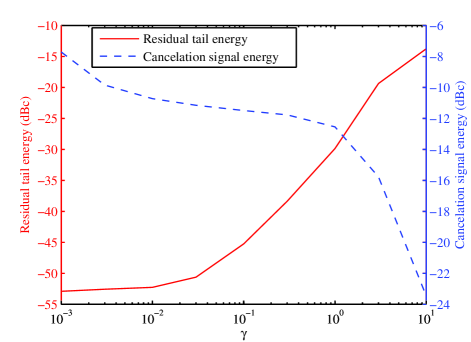
Fig. 4 shows the average residual tail and cancelation signal energy ( and , respectively) for a range of . Here, we have used PHYDAYS filter and the number of active subcarriers is equal to . The residual tail and cancelation signal energy are normalized with respect to the energy of each real-valued symbol (equivalently, the carrier) in the FBMC burst; the dBc unit in Fig. 4 refers to decibels relative to carrier. As observed, there is a wide range of the parameter that leads to a well-cancelled tail while the cancellation signal energy remains small. For instance, at the residual tail energy drops below dBc, and at the cancelation signal energy is still below dBc.
Other points that worth noting (but not shown in Fig. 4) are: (i) When no tail-shortening is applied (equivalently, ), the average tail energy is dBc. (ii) When , dBc and dBc. This value of , in particular, indicates the significance of factoring the cancelation signal energy in our design equations.
VI-B EVM Performance with Residual Tail Truncation
As discussed before, truncation of beyond incurs distortion to the edge data symbols. This distortion is quantified by looking at the error vector magnitude (EVM) of data symbols at the beginning and the end (i.e., the edge symbols) of each burst. EVM is defined as the mean square of the errors in the detected symbols at the receiver output, normalized to the energy of each real-valued symbol, when channel is free of noise.
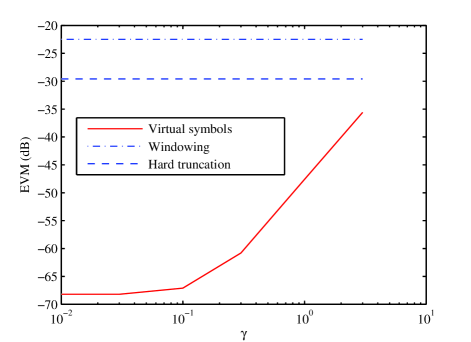
Fig. 5 plots EVM of the edge symbols for the proposed method within a range of , for the case of PHYDAYS filter and active subcarriers. Results of the hard truncation and truncation with windowing are also presented for comparison. The tails are truncated at for all the methods, therefore they all have the same tail overhead. The roll-off length is set to for the truncation with windowing method. As results show, the proposed tail-shortening by virtual symbols significantly outperforms the hard truncation and truncation with windowing. It is also interesting to note that, with respect to EVM, hard truncation outperforms truncation with windowing. This is because, for a set value of , windowing, in addition to hard truncation, adds some distortion to the first and last samples of each burst.
VI-C Error Performance without Residual Tail Truncation
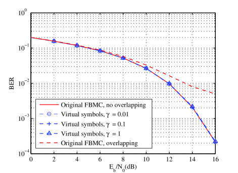
In this subsection, we simulate a transmitter that overlaps the residual tails within the adjacent packets, as shown in Fig. 3. This simulation aims to quantify how BER performance is affected by overlapping the residual tails with adjacent packets. The channel under simulation is an AWGN channel and no guard time between packets is provided. Fig. 6 shows the results with different values of , active subcarriers, -QAM modulation and PHYDAYS filter. Performance of the original FBMC-OQAM system without overlapping is also provided for comparison. As observed, overlapping the residual tails with adjacent packets causes no observable influence on the BER performance, with the selected ’s. In comparison, as also shown in Fig. 6, overlapped FBMC-OQAM packets without tail-shortening result in a significant degradation in BER.
VI-D PAPR
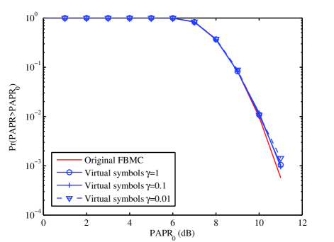
Fig. 7 demonstrates the PAPR of the FBMC bursts with the proposed tail-shortening, for the case of PHYDAYS filter and active subcarriers. PAPR of original FBMC signal is also presented for comparison. As observed, the proposed method has a minimal effect on PAPR.
VI-E PSD Performance
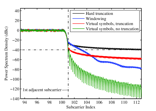
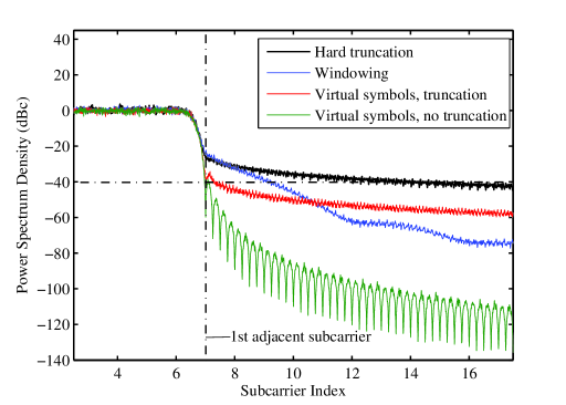
Figs. 8 and 9 show the power spectral density (PSD) of the proposed method with and active subcarriers, respectively. Here, we have adopted PHYDYAS filter and the parameters and are used. The performance of the original FBMC signal and those with hard truncation and truncation with windowing are also presented for comparison. For the latter methods, the tail overhead is the same as the method proposed in this paper. Clearly, by construction, the constructed waveforms according the method proposed in this paper have exactly the same PSD as the original FBMC signal, if the residual tail is not truncated. With tail truncation, the proposed tail-shortening method still achieves an OOB suppression of about dB at the first adjacent subcarrier, which is a far better performance than those of the hard truncation and truncation with windowing.
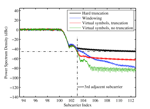
For IOTA filter, the PSD of the proposed method with and active subcarriers is presented in Fig. 10. Due to better concentration in time than PHYDYAS pulse, FBMC signal with IOTA pulse has a sharper transition at the tail however higher OOB emission at adjacent subcarriers. Therefore, even with truncation, the proposed virtual symbols method has a PSD performance with an OOB emission of around dB. Moreover, compared to the truncation with windowing, the proposed method has a deeper out-of-band suppression from the rd to the th adjacent subcarriers.
VI-F Comparison with UFMC and GFDM/C-FBMC
To complete our study and position the modified FBMC waveform against the recently proposed candidate waveforms for 5G, we compare the modified FBMC with UFMC, GFDM, and C-FBMC waveforms in terms of their OOB emission and the packet length overhead incurred due to relevant filtering operations. Noting that GFDM and C-FBMC have a very similar OOB emission, we only present the PSD results of C-FBMC as a representative of the two.
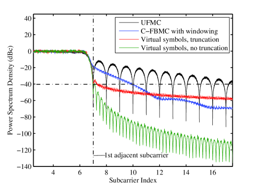
Fig. 11 presents a set of PSD plots of UFMC, C-FBMC, and the FBMC with virtual symbols. For UFMC, we have used the Dolph-Chebyshev filter with a stopband attenuation of 40 dB. In the literature, this choice has been widely advertised as the best compromised choice, [29, 30]. The FFT length in UFMC is set equal to 256 and the length of Dolph-Chebyshev filter is equal to 19. As seen, due to the short length of the Dolph-Chebyshev filter, UFMC has a poor OOB emission for many subcarriers before it reaches the set 40 dB attenuation. Such attenuation is achieved only at subcarriers that are more 12 subcarriers away from the last active subcarrier in the passband of the waveform. The C-FBMC has a better OOB emission performance, however, still it does not reach the 40 dB attenuation until the forth subcarrier away from the last active subcarrier in the passband. The proposed FBMC, on the other hand, easily drops below the 40 dB attenuation line at the center of the first subcarrier adjacent to the passband. This is nearly true even after truncation of its suppressed tails.
For the results presented in Fig. 11, in UFMC, the overhead introduced by the Dolph-Chebyshev filter is 7.03% of the transmit signal before passing through the Dolph-Chebyshev filter. C-FBMC and FBMC waveform parameters are chosen such both carry the same length of data (7 QAM symbols across time) and both have tail overhead of 7.14%. For C-FBMC, all the overhead has been used to introduce raise-cosine roll-offs, meaning there is no CP in the waveform. Hence, any CP that is added to take care of the channel will increase the overhead of the C-FBMC waveform and makes it longer than that of the FBMC waveform with virtual symbols. We thus see that while the modified FBMC which is proposed in this paper offers a superior performance in terms of OOB emission, it has a tail overhead that is comparable to or lower than that of its competitors.
VII Conclusions
In this paper, we proposed a method based on virtual symbols for tail-shortening in the FBMC-OQAM waveforms. The proposed method transmits a set of virtual symbols at the two sides of each data packet to suppress signal samples at the FBMC-OQAM tails. An optimization procedure was formulated to minimize the tail energy beyond a set sample index. Extensive simulations were presented with a tail overhead of on each side. The results showed that while the proposed method retains the excellent OOB emission performance of the conventional FBMC method, a very low EVM, and a very minimal change in PAPR, it results in a tail overhead that remains comparable to or lower than those of the UFMC, GFDM and C-FBMC, which in recent literature have been introduced as its competitors.
References
- [1] R. Van Nee and R. Prasad, OFDM for Wireless Multimedia Communications. Boston: Arthec House, 2000.
- [2] Y. Li and G. L. Stüber, eds., Orthogonal Frequency Division Multiplexing for Wireless Communications. New York, NY: Springer, 2006.
- [3] M. Morelli, C. C. J. Kuo, and M. O. Pun, “Synchronization techniques for orthogonal frequency division multiple access (OFDMA): A tutorial review,” Proc. of the IEEE, vol. 95, no.7, pp. 1394–1427.
- [4] V. Vakilian, T. Wild, F. Schaich, S. ten Brink, and J.-F. Frigon, “Universal-filtered multi-carrier technique for wireless systems beyond LTE,” in Globecom Workshops (GC Wkshps), 2013 IEEE, pp. 223–228, 2013.
- [5] X. Wang, T. Wild, F. Schaich, and A. dos Santos, “Universal filtered multi-carrier with leakage-based filter optimization,” in European Wireless 2014; 20th European Wireless Conference; Proceedings of, pp. 1–5, 2014.
- [6] T. Wild, F. Schaich, and Y. Chen, “5G air interface design based on universal filtered (UF-)OFDM,” in Digital Signal Processing (DSP), 2014 19th International Conference on, pp. 699–704, 2014.
- [7] F. Schaich and T. Wild, “Waveform contenders for 5G - OFDM vs. FBMC vs. UFMC,” in Communications, Control and Signal Processing (ISCCSP), 2014 6th International Symposium on, pp. 457–460, 2014.
- [8] F. Schaich and T. Wild, “Relaxed synchronization support of universal filtered multi-carrier including autonomous timing advance,” in Wireless Communications Systems (ISWCS), 2014 11th International Symposium on, pp. 203–208, 2014.
- [9] G. Fettweis, M. Krondorf, and S. Bittner, “GFDM - generalized frequency division multiplexing,” in Vehicular Technology Conference, 2009. VTC Spring 2009. IEEE 69th, pp. 1–4, 2009.
- [10] N. Michailow, M. Matthe, I. S. Gaspar, A. N. Caldevilla, L. L. Mendes, A. Festag, and G. Fettweis, “Generalized Frequency Division Multiplexing for 5th Generation Cellular Networks,” Communications, IEEE Transactions on, vol. 62, no. 9, pp. 3045–3061, 2014.
- [11] M. J. Abdoli, M. Jia, and J. Ma, “Weighted circularly convolved filtering in OFDM/OQAM,” in Personal Indoor and Mobile Radio Communications (PIMRC), 2013 IEEE 24th International Symposium on, pp. 657–661, 2013.
- [12] H. Lin and P. Siohan, “An advanced multi-carrier modulation for future radio systems,” in Acoustics, Speech and Signal Processing (ICASSP), 2014 IEEE International Conference on, pp. 8097–8101, 2014.
- [13] M. Schellmann, Z. Zhao, H. Lin, P. Siohan, N. Rajatheva, V. Luecken, and A. Ishaque, “FBMC-based air interface for 5G mobile: Challenges and proposed solutions,” in Cognitive Radio Oriented Wireless Networks and Communications (CROWNCOM), 2014 9th International Conference on, pp. 102–107, 2014.
- [14] H. Lin and P. Siohan, “Multi-carrier modulation analysis and WCP-COQAM proposal,” EURASIP Journal on Advances in Signal Processing, vol. 2014, no. 1, 2014.
- [15] B. Farhang-Boroujeny, “OFDM Versus Filter Bank Multicarrier,” IEEE Signal Processing Magazine, vol. 28, no. 3, pp. 92–112, 2011.
- [16] P. Siohan, C. Siclet, and N. Lacaille, “Analysis and design of OFDM/OQAM systems based on filterbank theory,” IEEE Transactions on Signal Processing, vol. 50, no. 5, pp. 1170–1183, 2002.
- [17] X. Gao, W. Wang, X.-G. Xia, E. K. S. Au, and X. You, “Cyclic Prefixed OQAM-OFDM and its Application to Single-Carrier FDMA,” Communications, IEEE Transactions on, vol. 59, no. 5, pp. 1467–1480, 2011.
- [18] B. Hirosaki, “An Orthogonally Multiplexed QAM System Using the Discrete Fourier Transform,” IEEE Transactions on Communications, vol. 29, no. 7, pp. 982–989, 1981.
- [19] D. Chen, D. Qu, T. Jiang, and Y. He, “Prototype Filter Optimization to Minimize Stopband Energy With NPR Constraint for Filter Bank Multicarrier Modulation Systems,” Signal Processing, IEEE Transactions on, vol. 61, no. 1, pp. 159–169, 2013.
- [20] H. Zhang, D. Le Ruyet, D. Roviras, and H. Sun, “Noncooperative Multicell Resource Allocation of FBMC-Based Cognitive Radio Systems,” Vehicular Technology, IEEE Transactions on, vol. 61, no. 2, pp. 799–811, 2012.
- [21] T. Ihalainen, A. Ikhlef, J. Louveaux, and M. Renfors, “Channel Equalization for Multi-Antenna FBMC/OQAM Receivers,” Vehicular Technology, IEEE Transactions on, vol. 60, no. 5, pp. 2070–2085, 2011.
- [22] S. Coleri, M. Ergen, A. Puri, and A. Bahai, “Channel estimation techniques based on pilot arrangement in OFDM systems,” Broadcasting, IEEE Transactions on, vol. 48, no. 3, pp. 223–229, 2002.
- [23] M. Bellanger, “Efficiency of Filter Bank Multicarrier Techniques in Burst Radio Transmission,” in Global Telecommunications Conference (GLOBECOM 2010), 2010 IEEE, pp. 1–4, 2010.
- [24] M. Bellanger, M. Renfors, T. Ihalainen, and C. A. F. da Rocha, “OFDM and FBMC transmission techniques: a compatible high performance proposal for broadband power line communications,” in Power Line Communications and Its Applications (ISPLC), 2010 IEEE International Symposium on, pp. 154–159, 2010.
- [25] M. G. Bellanger, “Specification and design of a prototype filter for filter bank based multicarrier transmission,” in Acoustics, Speech, and Signal Processing, 2001. Proceedings. (ICASSP ’01). 2001 IEEE International Conference on, vol. 4, pp. 2417–2420 vol.4, 2001.
- [26] S. Mirabbasi and K. Martin, “Overlapped complex-modulated transmultiplexer filters with simplified design and superior stopbands,” Circuits and Systems II: Analog and Digital Signal Processing, IEEE Transactions on, vol. 50, no. 8, pp. 456–469, 2003.
- [27] A. Viholainen, M. Bellanger, and M. Huchard, “Prototype filter and structure optimization,” website: www. ict-phydyas. org: Document D, vol. 5, 2009.
- [28] E. Dahlman, S. Parkvall, and J. Skold, 4G: LTE/LTE-advanced for mobile broadband. Academic press, 2013.
- [29] G. Wunder, P. Jung, M. Kasparick, T. Wild, F. Schaich, Y. Chen, S. Brink, I. Gaspar, N. Michailow, A. Festag, and Others, “5GNOW: non-orthogonal, asynchronous waveforms for future mobile applications,” Communications Magazine, IEEE, vol. 52, no. 2, pp. 97–105, 2014.
- [30] X. Wang, T. Wild, and F. Schaich, “Filter Optimization for Carrier-Frequency-and Timing-Offset in Universal Filtered Multi-Carrier Systems,” in Vehicular Technology Conference (VTC Spring), 2015 IEEE 81st, pp. 1–6, IEEE, 2015.