MPGD,2015 \woctitle4th Conference on Micro-Pattern Gaseous Detectors
A novel application of Fiber Bragg Grating (FBG) sensors in MPGD
Abstract
We present a novel application of Fiber Bragg Grating (FBG) sensors in the construction and characterisation of Micro Pattern Gaseous Detector (MPGD), with particular attention to the realisation of the largest triple (Gas electron Multiplier) GEM chambers so far operated, the GE1/1 chambers of the CMS experiment at LHC. The GE1/1 CMS project consists of 144 GEM chambers of about 0.5 m2 active area each, employing three GEM foils per chamber, to be installed in the forward region of the CMS endcap during the long shutdown of LHC in 2108-2019. The large active area of each GE1/1 chamber consists of GEM foils that are mechanically stretched in order to secure their flatness and the consequent uniform performance of the GE1/1 chamber across its whole active surface. So far FBGs have been used in high energy physics mainly as high precision positioning and re-positioning sensors and as low cost, easy to mount, low space consuming temperature sensors. FBGs are also commonly used for very precise strain measurements in material studies. In this work we present a novel use of FBGs as flatness and mechanical tensioning sensors applied to the wide GEM foils of the GE1/1 chambers. A network of FBG sensors have been used to determine the optimal mechanical tension applied and to characterise the mechanical tension that should be applied to the foils. We discuss the results of the test done on a full-sized GE1/1 final prototype, the studies done to fully characterise the GEM material, how this information was used to define a standard assembly procedure and possible future developments.
1 Introduction
To upgrade the Compact Muon Solenoid (CMSChatrchyan:2008aa )
muon system 144 GEM chambers will be installed in the high
pseudo-rapidity region of CMS during Long Shutdown 2 (LS2) of the Large Hadron Collider
Abbaneo:2014zxc . The GEMs can provide extra leverage on
precision studies of standard model physics, as well as open up a
window to explore exotic signatures with muons in the high
pseudorapidity region
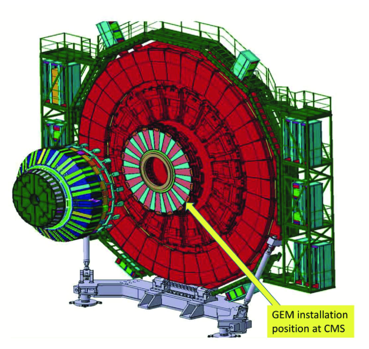
Abbaneo:2014lja . The GEM chambers will installed, as shown in fig. 1,
very close to the beam pipe where a high flux of low Pt muons is
expected. The GEM chambers can easily handle this rate due to their
high rate capability of 100 MHz/cm2. The large active area of each
GE1/1 (GEM Endcap) chamber, approximately 0.4 m2
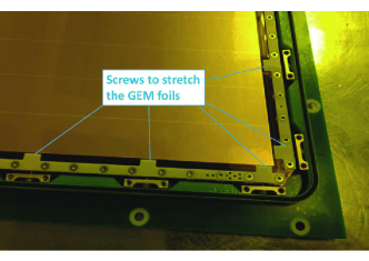
Colaleo:2021453 , consists of a triple-GEM foil stack stretched
by means of screws placed around the stack frame (fig.2). These
foils need to be stretched simultaneously in order to secure the
planarity and consequent uniform performance of the GE1/1 chamber
Abbaneo:2013nba . The GE1/1 detector technology used for CMS is
described in detail somewherelse Gilles .
The FBG sensors
act as low cost precision spatial and temperature sensing tools and
they are commonly used for strain measurements Benussi:2010yw
Caponero:2012py Benussi2012483 . These sensors are
commercially available and have relative low cost. In this work
FBG sensors are used to measure the planarity and mechanical tension
of the GEM foils in the GE1/1 chambers. The GE1/1 assembly procedure
employs a mechanical stretching procedure to apply tension to the GEM
foils by means of a series of lateral screws inserted into the
internal GE1/1 frame. This technology allows mechanical assembly of
the GEM chamber without the use of internal spacers or glue.
2 FBG sensors as a strain measurement
A FBG is a type of distributed Bragg reflector, constructed in a short segment of optical fiber that reflects particular wavelengths of light and transmits all others. The sensitivity of FBG in terms of strain, defined as relative elongation w.r.t. the initial position is of the order of 0.1 . This is achieved by creating a periodic variation in the refractive index of the fiber core, which generates a wavelength-specific dielectric mirror. Therefore it can be used as a strain measurement tool since variation of the FBG translates into different light frequency response.
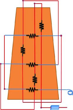
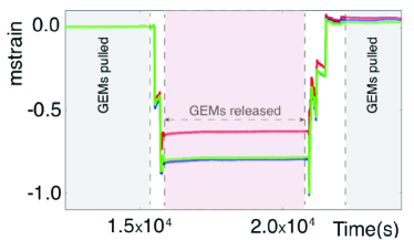
In order to validate the mechanical stretching technique a network of FBG sensors is affixed on the triple-GEM stack as shown in figure 3. Each sensor is glued on the GEM foil using a very thin layer of epoxy glue. Due to the high temperature sensitivity of the FBG the thermal dilatation of the materials used are corrected by using a separate FBG sensor on a 1010 cm2 GEM detector. The test is performed by modifying the stretching conditions of the GEM foils stack with real time monitoring and recording of the FBG sensors data. The test starts with the chamber normally assembled with the GEM stack mechanically stretched to the nominal tensile load. After some time while steady in the starting condition, the mechanical stretching of the GEMs is released and kept in such condition for several hours. Finally the GEMs are stretched again up to the nominal tensile load. The trends of the FBG sensors are shown in figure 4a.
The steep variations of the strain evident in figure 4a correspond to the actions of un-screwing and screwing the mechanical stretchers during the test. The initial stretch value is assumed as reference condition with strain = 0. When stretchers are un-screwed the strain goes to the lower value, different strain values apply to different foils as they fold quasi-free and assume unequal conditions. After the stretchers are screwed back, the strain value is similar for all foils, showing that they all experience similar stretching, about the original value of the reference condition. Thus it can be inferred that at the predetermined tensile load all foils reach a similar stretched level although they started from different values. From the plot it can be seen that all the sensors of the network react at the same moment. These results allow us to validate the mechanical stretching assembly technique for GE1/1 chambers. Further tests are ongoing to confirm other important parameters such as the optimal tensile load to be applied to the GEMs and the maximum planarity obtainable for the GEMs without applying a load beyond the Young’s region for GEM foils.
3 Another FBG application: the load gauge
Another important application of FBG in GEM chamber construction is the possibility to be used as load gauge for precise measurement of the tensile load applied to the foils, of the different layers, in the same moment. This is extremely important in the case of the GE1/1 chambers since, during their assembly procedure, the foils are stretched by means of screwing nuts with dynamometric screwdriver. It is thus very important to know precisely how much to pull the foils in order to avoid to stretch them too much, reaching the mechanical load with will cause the GEM foils to be operated outside their elastic range (Young region). In order to demonstrate the idea of FBG as load gauge we have done the following test which results in terms of FBG response are shown in figure 4b. After having properly stretched the GE1/1 GEM stack, we have removed a single stretching screw from the chamber and replaced it with an eyelet screw on which we have fixed a stainless steel wire used to attach different weights. The idea was to add weights in different steps till they applied load reproduce in the FBG facing the eyelet the same response when the GEMs are stretched by means of the original screw.
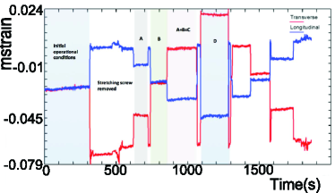
In this test few sample of weights (lead bricks) are used. We took 4 points corresponding to the following weights A=2.86 kg, B=5.65 kg, C=8.5 kg, D=11.3 kg. Fig 4b shows the response of the FBG during this test. The RED and BLUE lines correspond to the two sensors closest to the point where the load is applied (RED sensor parallel to the line of the stainless steel wire, BLUE orthogonal to the wire direction). In the plot are visible different regions corresponding to the different actions performed to the foils. The first flat region correspond to the initial position of the foils stack, meaning the GEMs properly stretched with the original screw. Then the screw is removed and the two sensors immediately record the effect on the foils tension. There are some movements in the following flat regions due to the handling during the substitution of the screw. The first weight A applied shows its effect on the sensors. Then weight A is removed to load weight B (it is visible the short foils relaxation during this action). The third step was to add the weight A to B and after removing A+B (weight C) we add weight E. Finally we redo the same steps backwards as shown in the plot, removing the weights in steps. By analysing the plots shown in fig. 4b we were able to determine the load applied on a single screw once the GEM stack is stretched to its operational value. This value is of the order 5.65 kg and is very close to the expected value of 3 kg/cm considering that the crimping length of one screw is 2 cm. This result is important since other measurements presented in this conference shown that the GEM foils Young region ends around 8 kg/cm. This value ensures that the mechanical tension applied to GEM foils is still in the elastic regime by a wide margin.
4 Conclusion
With the use of FBG sensors we successfully demonstrated that the novel glue-less technique adopted to assemble the GE1/1 chambers for the LS2 update of CMS is reliable and guarantees the correct tensioning of the three GEM foils. By applying the correct tension across the GEM stack the uniform gaps spacing is obtained, which is extremely important to get the required performance of the detector. We have also demonstrated the FBG are excellent load gauges that can be used to determine very precisely the applied stretching force to GEM foils which is a critical point for the correct assembly of the GE1/1 chambers and to secure their homogeneity. Other tests are ongoing by using the same FBG sensors to optimise the tensile load in order to avoid damage and guarantee planarity of the GEM foils.
Acknowledgments
We gratefully acknowledge the support of FRS-FNRS (Belgium), FWO-Flanders (Belgium), BSF-MES (Bulgaria), BMBF (Germany), DAE (India), DST (India), INFN (Italy), NRF (Korea), QNRF (Qatar), and DOE (USA). This project has received funding from the European Unionâs Horizon 2020 Research and Innovation programme under Grant Agreement no. 654168.
References
- (1) S. Chatrchyan et al. [CMS Collaboration], JINST 3, S08004 (2008). doi:10.1088/1748-0221/3/08/S08004
- (2) D. Abbaneo et al., Performance of a Large-Area GEM Detector Prototype for the Upgrade of the CMS Muon Endcap System, arXiv:1412.0228v2, 8 Dec 2014.
- (3) D. Abbaneo et al., Upgrade of the CMS muon system with triple-GEM detectors, JINST 9 (2014) C10036, http://iopscience.iop.org/1748-0221/9/10/C10036/.
- (4) A. Colaleo et al., CMS TECHNICAL DESIGN REPORT FOR THE MUON ENDCAP GEM UPGRADE, CERN-LHCC-2015-012. CMS-TDR-013, https://cds.cern.ch/record/2021453.
- (5) D. Abbaneo et al.,Status of the Triple-GEM project for the upgrade of the CMS Muon System, DOI: 10.1088/1748-0221/8/12/C12031.
- (6) Gilles De Lentdecker for the CMS GEM collaboration"Status Report of the Upgrade of the CMS muon system with triple-GEM detectors". Elba 2015 confernce proceeding under publication.
- (7) L. Benussi et al.,The Omega-like: A novel device using FBG sensors to position vertex detectors with micrometric precision, Nucl.Phys.Proc.Suppl. 172.
- (8) M. Caponero et al., Use of fiber optic technology for relative humidity monitoring in RPC detectors, Published in PoS RPC2012 (2012) 073.
- (9) L. Benussi et al., A Novel Temperature Monitoring Sensor for Gas-Based Detectors in Large HEP Experiments, doi = "http://dx.doi.org/10.1016/j.phpro.2012.02.400"