On-chip microwave-to-optical quantum coherent converter based on a superconducting resonator coupled to an electro-optic microresonator
Abstract
We propose a device architecture capable of direct quantum electro-optical conversion of microwave to optical photons. The hybrid system consists of a planar superconducting microwave circuit coupled to an integrated whispering-gallery-mode microresonator made from an electro-optical material. We show that by exploiting the large vacuum electric field of the planar microwave resonator, electro-optical (vacuum) coupling rates as large as kHz are achievable with currently available technology – a more than three order of magnitude improvement over prior designs and realizations. Operating at millikelvin temperatures, such a converter would enable high-efficiency conversion of microwave to optical photons. We analyze the added noise, and show that maximum quantum coherent conversion efficiency is achieved for a multi-photon cooperativity of unity which can be reached with optical power as low as .
The interconversion of microwave and optical signals is of practical relevance in a broad range of electronic applications, from optical and wireless communications to timing. The spectacular advances of the past decade in manipulating the quantum states of the microwave field Hofheinz et al. (2009); Devoret and Schoelkopf (2013) has increased interest in techniques to convert them to optical fields, since the latter can be propagated via optical fiber at room temperature while preserving their quantum state. In the long term, converting quantum states between microwave and optical photons may enable long distance quantum communication Barzanjeh et al. (2012); Kimble (2008), and in the near term, it provides a path towards realizing single photon detectors of the microwave field that may find use in quantum science and metrology, radio astronomy and technology alike. For these reasons, hybrid systems for such microwave to optical interfaces have recently attracted significant experimental efforts. Several approaches have been investigated Tian (2015); Schoelkopf and Girvin (2008): optomechanical and electromechanical devices Bochmann et al. (2013); Bagci et al. (2014); Andrews et al. (2014); Pirkkalainen et al. (2013) as well as cold atoms Hafezi et al. (2012) and spin ensembles Kubo et al. (2010); Williamson et al. (2014). Indeed, a bi-directional and efficient link has been established recently using a mechanical oscillator coupled to both optical and microwave modes. Alternatively, it has been proposed that the parametric coupling of an LC circuit to an optical cavity via an electro-optical crystal would realize an effective optomechanical-type interaction Tsang (2010). Such a system could convert states from the microwave to the optical domain by driving sideband cooling transitions Marquardt et al. (2007); Wilson-Rae et al. (2007); Schliesser et al. (2008). Similar to optomechanical systems, the interaction requires large vacuum coupling rates and the resolved-sideband regime Marquardt et al. (2007); Wilson-Rae et al. (2007); Schliesser et al. (2008) to be efficient as well as a optical cavity decay rate that greatly exceeds the microwave decay rate. Despite interest in the scheme, to date, it has not been realized. Previous demonstrations attained vacuum coupling rates of Hz insufficient for an efficient transfer. In addition, several previous schemes operated with a microwave dissipation that was larger than the optical one, preventing efficient transfer from optical to microwave fields. Here, we show that these two requirements can be fulfilled in principle by coupling the electric field of a superconducting resonator to a whispering-gallery-mode (WGM) microresonator made from an electro-optical material, benefiting from the large vacuum electric field of superconducting circuits, akin to cQED Wallraff et al. (2004).
Theoretical description. In the most general form, the cavity electro-optical dynamics is described by the Hamiltonian Tsang (2010)
| (1) |
where and ( and ) are the optical (microwave) annihilation and creation operators and () the optical (microwave) angular resonant frequency. The electro-optic coupling coefficient is given by
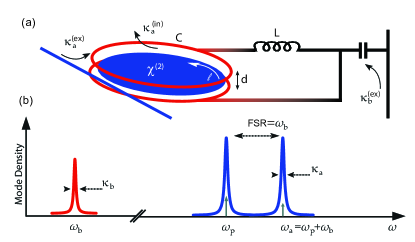
for a generic geometry (as depicted in Fig. 1), where is the optical refractive index of the nonlinear medium, is its electro-optic coefficient, is the length of the medium along the optical path (such that ), is its thickness, and is the optical round-trip time. is the zero-point fluctuation of the microwave field at resonant frequency .
The converter operation uses the fact that the electro-optical interaction is formally equivalent to the optomechanical Hamiltonian, whereby the microwave field plays the role of the mechanical degree of freedom. Consequently, in the good cavity limit (resolved sideband regime), i.e. , and when optical dissipation dominates, i.e. , pumping the system with an optical laser on the lower sideband (), will in the linearized regime lead to a beam-splitter interaction Hamiltonian which effectively sideband cools the microwave mode, i.e. converts the microwave state to an optical photon at frequency . For the case of a zero temperature bath and a pulsed optical cooling field, the input state of the microwave field and the optical field are swapped and state transfer achieved Tsang (2010). While electro-optical materials have been widely employed in modern optical telecommunication, realizing the conversion scheme in this manner has been challenging Ilchenko et al. (2003); Strekalov et al. (2009), due to the inability to achieve large overlap of the microwave and optical field, resulting in insufficient coupling rates. Moreover, while crystalline WGM Ilchenko et al. (2004) can attain ultra high quality factors (Q), it poses stringent conditions on the microwave Q to achieve the proper dissipation hierarchy for conversion.
For a WGM resonator coupled to an LC circuit the electro-optic coupling coefficient can be expressed as
| (2) |
where the only geometrical parameter is the microwave mode volume . Therefore to attain a large vacuum coupling rate , a large overlap of the electric field distribution and the optical mode of the cavity has to be attained. This formula also emphasizes that a material with high electro-optic coefficient , high refractive index and low microwave dielectric constant are preferable.
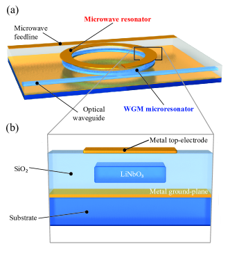
Device implementation. To enable sizeable electro-optical coupling to an integrated nonlinear optical microresonator on the same chip, the proposed new underlying hybrid device architecture uses the large vacuum electric field offered by superconducting resonators, which confine electromagnetic modes to small volume and commonly exhibit high-Q. Indeed, titanium nitride TiN resonators can attain quality factors as high as Leduc et al. (2010) at millikelvin temperatures. The proposed on chip, integrated device is based on an optical WGM microresonator made from a material that features nonlinearity, such as lithium niobate () or aluminium-nitride () Guarino et al. (2007); Xiong et al. (2012). As shown schematically in Fig. 2, the planar microresonator is coupled to an open superconducting microstrip resonator, whose electric field couples to the optical mode via the electro-optical effect. Note here that the symmetry of the microwave resonator must be broken to ensure that only the positive phase of the microwave electric field profile couples to the optical microresonator. The fabrication of microresonators from electro-optical materials is made possible via crystalline thin films 111which has recently become commercially available from NanoLN, which allow to combine the large on-chip element density of integrated photonics with the second-order nonlinearity of . Microresonators with Q have been demonstrated with this material Wang et al. (2015).
Because of the absence of a symmetry center, nonlinear materials also exhibit piezoelectricity, which can cause modulation of the optical field Wang and Bhave (2014) and perturb the electro-optic modulation via the Pockels effect. By design, the microring is embedded in silica () and thus is clamped. Hence, the mechanical degree of freedom is frozen and the piezoelectric contribution to the modulation made negligible. This result was verified by a simulation comparing a suspended microdisk and an embedded microring of same geometries under the same microwave excitation. For the latter, the piezoelectric coupling strength is more than 9 orders of magnitude smaller and therefore can be neglected. Our device and simulation efforts focused on Z-cut after having discarded other potential nonlinear materials. exhibits a as high as 30. Nanofabrication platforms are also mature enough to provide good structures with thin-film single crystals Poberaj et al. (2012); Xiong et al. (2012). We conducted numerical simulations in order to take into account the anisotropy of the material and the complex geometry of our design.
Numerical simulations.
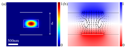
In order to numerically evaluate the coupling coefficient of our proposed design we use finite element (FEM) simulation of the optical modes via the weak formulation of the Helmholtz equation Oxborrow (2007). We solve for eigenstates of the system in 2D representation with an axial symmetry simplification Oxborrow (2007). A FEM simulation of the optical mode for LiNbO3 is shown in Fig. 3. Since the WGM resonator has nonlinearity, an external microwave field will change the refractive index and thus modify the optical field. To introduce the electro-optical interaction, we use an expansion of the impermeability
| (3) |
We only keep the second term in the expansion corresponding to the second-order nonlinear effect, so called Pockels effect. The electro-optic tensor being not axisymmetric, thus one has to integrate the electro-optical interaction over the angular coordinate along the WGM optical mode.
To evaluate the (vacuum) electro-optical coupling rate , one has to compute the frequency shift caused by the microwave zero-point voltage fluctuations and corresponding . Then the electro-optic coefficient reads where is the voltage applied for the simulation and depends only on the microwave field distribution that we simulate (as shown in Fig. 3).
The Bethe-Schwinger cavity perturbation formula Schwinger (1943) can be used at a first-order approximation assuming that the perturbation has a small effect on the cavity:
| (4) |
where is the integration volume. For a high-Q resonator the radiation losses are small and the integration volume can be taken over the boundaries of the resonator. Eq. (4) can be written as i.e. as the ratio between the optical energy introduced by the perturbation () and the total energy of the unperturbed cavity (). As the effect is very weak, the optical energy variation is induced only by a modification of the resonator permeability constant One can write
| (5) |
where is an unperturbed electric displacement field of an optical mode. can then be determined by separately simulating the optical and microwave fields’ distributions.
Therefore, taking into account the geometry and the anisotropy of the system, the expression (2) of the electro-optical coupling coefficient becomes
| (6) |
An optimization of the different parameters, such as position and size of the microwave microstrip or polarization, was run in order to maximize . In particular, from Eq. (5) one can extract that TE optical modes characterized by high axial components give higher coupling. For the geometry in Fig. 3, we compute at (i.e. nm) and with . This value is more than 3 orders of magnitude larger than previous work Ilchenko et al. (2003); Strekalov et al. (2009). The position of the electrodes is critical. Electrodes on top (as in Fig. 3) proves to give higher coupling and are more convenient for fabrication (compared to electrodes on the side of the optical WGM, with similar distance to the WGM). The distance between the electrodes is key to provide high-confinement of the field. However it must be kept in mind as well that the quality factors of both optical and microwave cavities depend on the geometry. For instance, no metal should directly be too close to the evanescent field of the optical waveguide fields. For the geometries G1-G4 in Table 1, the field energy density at the position of the electrodes is 6 orders of magnitude smaller than that at the center of the mode, and therefore absorption is strongly reduced. Parameters and results are detailed in Table 1 for different optimum geometries.
| Geometry | G1 | G2 | G3 | G4 |
|---|---|---|---|---|
| Model | ||||
| (kHz) | 0.15 | 0.75 | 12 | 50 |
| (W) – single mode | ||||
| (W) – dual mode |
Scheme. By pumping the lower sideband of the hybrid electrooptical system at (see Fig. 1) the microwave photons are laser cooled, i.e. up-converted to the cold optical mode. If the microwave cavity is already cooled to the ground state by passive cooling, which is easily achieved in the case of superconducting cavity with GHz resonance frequency cooled to the base temperature of a dilution refrigerator, this up-conversion may be used to establish a coherent interface between microwave and optical fields. The proposed converter would work at , a typical frequency of microwave superconducting qubits Barends et al. (2013), and 10 mK to assure the microwave cavity ground state.
The main objective of the device is to achieve quantum coherent microwave-to-optical frequency conversion: to achieve near-complete frequency conversion (i.e. quantum efficiency ), the extrinsic decay rate of the optical cavity should dominate the intrinsic one and the effective coupling rate between the optical and the microwave modes should satisfy the hierarchy , where is the number of photons in the optical cavity, such that the frequency up-converted microwave photon leaves the optical cavity before it decays or is down-converted back to the microwave frequency range; the microwave cavity should be strongly overcoupled () . The overall intrinsic efficiency of the frequency up-conversion process , defined by the efficiency of converting microwave to optical quanta, can be calculated as
| (7) |
thus the overall efficiency is a function of frequency and cooperativity , which is proportional to the number of photons in the optical cavity , where is the electrooptical single-photon cooperativity. Interestingly, in our proposed scheme when , a cooperativity of is sufficient to obtain the maximum efficiency Tsang (2011), making achievable the complete photon conversion between microwave and optical fields on a chip.
The quantum-state-transfer is only possible if a unity cooperativity is achieved and the coupling strength is much larger than the microwave decay rates , i.e. . When implementing the converter with a single optical resonance (cf. Table 1) the required power levels are of the order of milliwatts or even higher, making a realistic implementation impossible. The power can however be substantially reduced by employing two optical modes (cf. Fig. 1), spaced by the microwave frequency (i.e. a multiple cavity mode transducer Dobrindt and Kippenberg (2010)). In this case, when , one has
| (8) |
where is the optical pump power. With such a dual mode design, the pump power required to obtain is and can be as low as with conservative parameters slightly better than and . Thus according to expression (7), a conversion efficiency exceeding 90% can be achieved with of pump power with the presented design. In contrast to the realization with the only optical mode, in the dual-optical-mode scheme the required power does reduce when increases. For instance, for the state-of-the-art parameters of and one would need of optical power only.
The noise introduced by the coupling of modes other than the incoming microwave signal limits the quantum fidelity of the microwave to optical photon conversion. We theoretically characterized the noise added during the conversion process by the equivalent quanta of the total noise, as compared to the spectral density of the input signal. On resonance, we find that
| (9) |
quanta of noise are introduced, with the thermal occupation of the microwave mode. The first term gives the noise contribution from the microwave, and the second from the optical degrees of freedom. For strongly overcoupled resonators, one would only add .
Conclusions. In conclusion, we propose a direct quantum electrooptical converter based on a nonlinear WGM microresonator coupled to a planar superconducting microwave resonator which realizes large coupling rates. Electro-optical coupling coefficient as high as kHz can be attained with LiNbO3 thin films. We show that high-fidelity conversion can be achieved based on current technology with optical power as low as . On-chip, it will become efficiently coupled to and controlled by optical fields and thus may enable new regimes for radio- and microwave electromagnetic field detection (allowing quantum-limited amplification and readout of microwave and radio-frequency radiation). For instance, the proposed device could enable quantum microwave illumination Barzanjeh et al. (2015).
Acknowledgements.
This work was financially supported by the SNF, the NCCR Quantum Science and Technology and the European Union Seventh Framework Program through iQUOEMS (grant no.323924). TJK acknowledges financial support from an ERC AdG (QREM).References
- Hofheinz et al. (2009) M. Hofheinz, H. Wang, M. Ansmann, R. C. Bialczak, E. Lucero, M. Neeley, a. D. O’Connell, D. Sank, J. Wenner, J. M. Martinis, and a. N. Cleland, Nature 459, 546 (2009).
- Devoret and Schoelkopf (2013) M. H. Devoret and R. J. Schoelkopf, Science 339, 1169 (2013), http://science.sciencemag.org/content/339/6124/1169.full.pdf .
- Barzanjeh et al. (2012) S. Barzanjeh, M. Abdi, G. J. Milburn, P. Tombesi, and D. Vitali, Physical Review Letters 109, 130503 (2012).
- Kimble (2008) H. J. Kimble, Nature 453, 1023 (2008).
- Tian (2015) L. Tian, Annalen der Physik 527, 1 (2015).
- Schoelkopf and Girvin (2008) R. J. Schoelkopf and S. M. Girvin, Nature 451, 664 (2008).
- Bochmann et al. (2013) J. Bochmann, A. Vainsencher, D. D. Awschalom, and A. N. Cleland, Nature Physics 9, 712 (2013).
- Bagci et al. (2014) T. Bagci, A. Simonsen, S. Schmid, L. G. Villanueva, E. Zeuthen, J. Appel, J. M. Taylor, A. Sorensen, K. Usami, A. Schliesser, and E. S. Polzik, Nature 507, 81 (2014).
- Andrews et al. (2014) R. W. Andrews, R. W. Peterson, T. P. Purdy, K. Cicak, R. W. Simmonds, C. A. Regal, and K. W. Lehnert, Nature Physics 10, 321 (2014).
- Pirkkalainen et al. (2013) J.-M. Pirkkalainen, S. U. Cho, J. Li, G. S. Paraoanu, P. J. Hakonen, and M. A. Sillanpää, Nature 494, 211 (2013).
- Hafezi et al. (2012) M. Hafezi, Z. Kim, S. L. Rolston, L. A. Orozco, B. L. Lev, and J. M. Taylor, Physical Review A 85, 020302 (2012).
- Kubo et al. (2010) Y. Kubo, F. R. Ong, P. Bertet, D. Vion, V. Jacques, D. Zheng, A. Dréau, J.-F. Roch, A. Auffeves, F. Jelezko, J. Wrachtrup, M. F. Barthe, P. Bergonzo, and D. Esteve, Physical Review Letters 105, 140502 (2010).
- Williamson et al. (2014) L. A. Williamson, Y.-H. Chen, and J. J. Longdell, Phys. Rev. Lett. 113, 203601 (2014).
- Tsang (2010) M. Tsang, Physical Review A 81, 063837 (2010).
- Marquardt et al. (2007) F. Marquardt, J. Chen, A. Clerk, and S. Girvin, Physical Review Letters 99, 093902 (2007).
- Wilson-Rae et al. (2007) I. Wilson-Rae, N. Nooshi, W. Zwerger, and T. Kippenberg, Physical Review Letters 99, 093901 (2007).
- Schliesser et al. (2008) A. Schliesser, R. Rivière, G. Anetsberger, O. Arcizet, and T. J. Kippenberg, Nature Physics 4, 415 (2008).
- Wallraff et al. (2004) A. Wallraff, D. I. Schuster, A. Blais, L. Frunzio, R.-S. Huang, J. Majer, S. Kumar, S. M. Girvin, and R. J. Schoelkopf, Nature 431, 162 (2004).
- Ilchenko et al. (2003) V. S. Ilchenko, A. A. Savchenkov, A. B. Matsko, and L. Maleki, Journal of the Optical Society of America B 20, 333 (2003).
- Strekalov et al. (2009) D. V. Strekalov, A. A. Savchenkov, A. B. Matsko, and N. Yu, Optics letters 34, 713 (2009).
- Ilchenko et al. (2004) V. Ilchenko, A. Savchenkov, A. Matsko, and L. Maleki, Physical Review Letters 92, 043903 (2004).
- Leduc et al. (2010) H. G. Leduc, B. Bumble, P. K. Day, B. H. Eom, J. Gao, S. Golwala, B. a. Mazin, S. McHugh, A. Merrill, D. C. Moore, O. Noroozian, A. D. Turner, and J. Zmuidzinas, Applied Physics Letters 97, 102509 (2010).
- Guarino et al. (2007) A. Guarino, G. Poberaj, D. Rezzonico, R. Degl’Innocenti, and P. Günter, Nature Photonics 1, 407 (2007).
- Xiong et al. (2012) C. Xiong, W. H. P. Pernice, X. Sun, C. Schuck, K. Y. Fong, and H. X. Tang, New Journal of Physics 14, 095014 (2012).
- Note (1) Which has recently become commercially available from NanoLN.
- Wang et al. (2015) J. Wang, F. Bo, S. Wan, W. Li, F. Gao, J. Li, G. Zhang, and J. Xu, Opt. Express 23, 23072 (2015).
- Wang and Bhave (2014) R. Wang and S. A. Bhave, (2014), arXiv:1409.6351 .
- Poberaj et al. (2012) G. Poberaj, H. Hu, W. Sohler, and P. Günter, Laser & Photonics Reviews 6, 488 (2012).
- Oxborrow (2007) M. Oxborrow, in Proc. of SPIE, Vol. 6452, edited by A. V. Kudryashov, A. H. Paxton, and V. S. Ilchenko (2007) pp. 64520J–64520J–12.
- Schwinger (1943) J. Schwinger, MIT Radiation Laboratory Report no. 43-34 (1943).
- Barends et al. (2013) R. Barends, J. Kelly, A. Megrant, D. Sank, E. Jeffrey, Y. Chen, Y. Yin, B. Chiaro, J. Mutus, C. Neill, P. O’Malley, P. Roushan, J. Wenner, T. C. White, A. N. Cleland, and J. M. Martinis, Phys. Rev. Lett. 111, 080502 (2013).
- Tsang (2011) M. Tsang, Physical Review A 84, 043845 (2011).
- Dobrindt and Kippenberg (2010) J. M. Dobrindt and T. J. Kippenberg, Physical Review Letters 104, 033901 (2010).
- Barzanjeh et al. (2015) S. Barzanjeh, S. Guha, C. Weedbrook, D. Vitali, J. H. Shapiro, and S. Pirandola, Phys. Rev. Lett. 114, 080503 (2015).