Complete Coherent Control of a Quantum Dot Strongly Coupled to a Nanocavity
Abstract
Strongly coupled quantum dot-cavity systems provide a non-linear configuration of hybridized light-matter states with promising quantum-optical applications. Here, we investigate the coherent interaction between strong laser pulses and quantum dot-cavity polaritons. Resonant excitation of polaritonic states and their interaction with phonons allow us to observe coherent Rabi oscillations and Ramsey fringes. Furthermore, we demonstrate complete coherent control of a quantum dot-photonic crystal cavity based quantum-bit. By controlling the excitation power and phase in a two-pulse excitation scheme we achieve access to the full Bloch sphere. Quantum-optical simulations are in good agreement with our experiments and provide insight into the decoherence mechanisms.
Introduction
The rapid technological development of classical computing will soon reach fundamental limitations resulting from device miniaturization. However, the quantum regime and integration of optics on existing computing platforms offer a wide range of possibilities for overcoming the obstacles of Moore’s law or charge carrier mobility.
First approaches to develop quantum technologies were made in atomic physics 1, while real-world applications are more likely to be realized in solid state quantum systems 2, 3, 4, 5. Self-assembled quantum dots (QDs) are particularly attractive due to their optical addressability, their narrow linewidths and ease of integration into optoelectronic devices. To make use of these promising characteristics, complete coherent control of the quantum device is a necessity. For QDs this has already been widely explored in excitons 6, 7, 8. Yet, the operational-range and the physical properties of QDs are limited, in particular low emission rates impede their application as non-classical light sources in photonic devices. Furthermore, the strength of their coupling to light poses challenges for the on-chip realization of quantum networks.
In contrast, strongly coupled QD-cavity systems offer highly efficient out-coupling allowing for on-chip integration 9, 10, 11, 12. Moreover, they have proven to be extremely versatile, since the hybridization of electromagnetic waves and matter forms polaritons, yielding rich physical characteristics. In particular, it is possible to control the spontaneous emission of a QD in an optical cavity13, while the interaction of excitons and phonons14 allows for applications such as indistinguishable photon generation15. Future applications can profit from the systems’ interesting and especially useful physics far beyond that offered by QDs alone. Examples include high-fidelity photon-blockade 16, non-classical light generation 17, single spin-photon interfaces enabling compact on-chip quantum circuits 18 and dynamic cavity frequency tuning with surface acoustic waves 19. One crucial element that is needed for successful on-chip integration of strongly coupled systems is coherent control.
As discussed theoretically 20, dissipation hindered the complete coherent control of QD-cavity systems so far. In this work, we overcome this dissipation obstacle and demonstrate complete coherent control of a QD-photonic crystal cavity system. In experiments supported by simulations, we map out the excitation power and phase-dependent emission from a polaritonic system and we demonstrate full access of the Bloch sphere.
Results
Strongly coupled QD-photonic crystal cavity system
A system composed of a single QD strongly coupled to an L3 photonic crystal cavity 21 is the focus of our investigations. This type of cavity offers very high quality factors as well as low mode volumes 22, which allows the light-matter interaction to reach the strong-coupling regime 23. Details on the sample fabrication can be found in the Methods section.
The physics of a strongly coupled system is described by the Jaynes-Cummings (JC) model 24, with the Hamiltonian . The contributions are
| (1) |
with the cavity field Hamiltonian , the QD Hamiltonian and the QD-cavity interaction Hamiltonian , respectively. The cavity frequency is given by , while is the cavity mode photon annihilation operator, the QD’s lowering operator, the QD-cavity detuning and the coupling strength of the quantum emitter and the cavity.
A full description of the system’s complex eigenenergies is obtained by the addition of dissipation to the system and consists of a series of polariton rungs 25:
| (2) |
where represents the energy of the th rung, while and are the cavity and the QD energy decay rates, respectively.
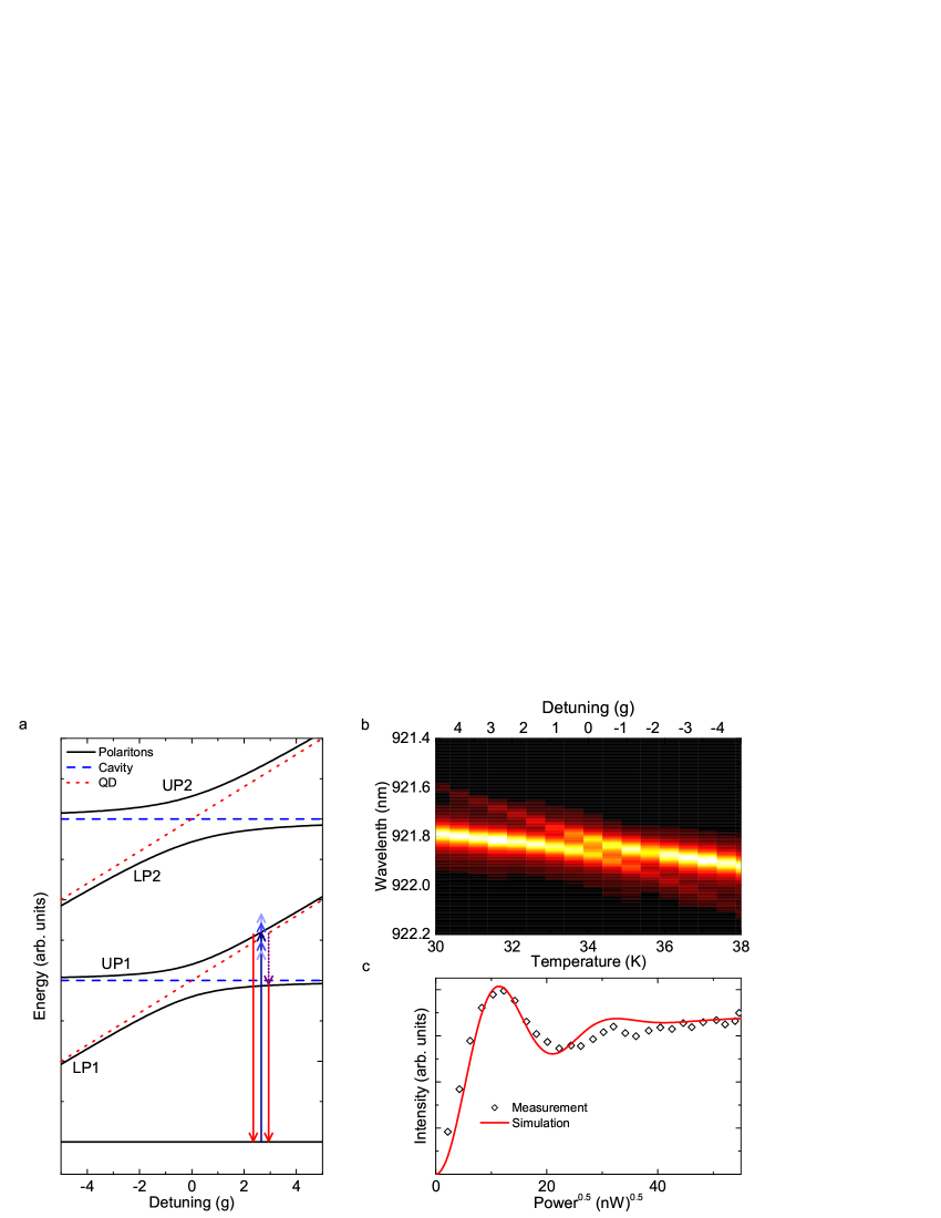
The energy level structure resulting from equation 2, called the JC ladder, is shown in figure 1a. The polariton rungs are indexed by and each rung is divided into a lower polariton (LP) and an upper polariton (UP). Red dotted lines indicate the energy levels of the uncoupled quantum emitter and blue dashed lines the ones of the cavity. The polariton branches show anticrossings which are known as a convincing signature of strong coupling 26, 27.
Experimentally, the anti-crossing of the lowest energy rung can be measured using cross-polarized reflectivity 28. The result of a typical measurement is presented in figure 1b. Here, the detuning between QD and cavity is controlled by changing the sample temperature 23, 28, 29. Fitting this data with equation 2 reveals values of GHz and GHz. The value of cannot be fitted directly as it is much smaller than the other rates due to the highly dissipative character of solid-state systems. Typical values in literature are GHz 28, 30. Importantly, compared to QDs in a bulk environment, the QD energy decay rate is further reduced due to Purcell suppression in the photonic bandgap.
Coherent control of JC polaritons
The coherent control of the population of exciton states in self-assembled QDs 7, 31, 32 or of quantum well-microcavity polaritons 33 is routinely performed. However, for polaritonic states of JC systems, the situation is more complicated due to the higher rungs of the JC ladder. In particular, for currently achievable system parameters and the QD in resonance with the cavity, a short-pulsed laser in resonance with the first rung would also be resonant with higher rungs of the ladder, preventing coherent control of a specific rung 16. Moreover, the presence of the higher rungs results in strong coherent scattering of the excitation laser 34, which would dominate over the signal of interest at excitation powers needed for coherent control.
We will now detail how we overcome both of these obstacles. To achieve a coherent interaction with a specific rung, the excitation laser needs to be spectrally narrow enough to prevent overlap with other rungs. At the same time, the pulse length needs to be shorter than the state lifetime to prevent re-excitation. At zero QD-cavity detuning all resonances of the JC ladder are very close. However, with increasing detuning between the QD and cavity, the energy difference between the two polariton branches within one rung becomes larger as the polaritons gradually evolve into the bare QD and cavity states 16. Importantly, when exciting the QD-like polaritonic branch with increasing detuning, the overlap with higher rungs decreases 16. Moreover, when the state becomes more QD-like, then the lifetime increases. This allows for a compromise between laser spectral width and pulse length to resonantly access the individual polariton branches (see figures 1a and 1b).
Note that the polaritons are a superposition of the bare QD eigenstates and the bare cavity eigenstates. During the experiments we will focus on detunings of and . At a detuning of we find UP1 to be approximately QD-like and cavity-like, while it is approximately QD-like and cavity-like at a detuning of . Although the influence of the cavity seems to be insignificant, the QD-like polariton emits almost only through the cavity mode. This is due to the Purcell suppression of non-cavity modes and is true for detunings of up to approximately 16. In fact, the cavity completely determines the system’s dynamics and the strong coupling leads to emission rates and an oscillator strength that is three orders of magnitude stronger than in the weak coupling regime. Thus, it is extremely difficult to observe the emission of a weakly coupled system in standard cross-polarized resonance fluorescence since the coherent scattering of the laser light dominates the signal.
We exploit the efficient exciton-phonon coupling to avoid the strong coherent scattering of the excitation laser dominating the resonance fluorescence signal. Investigations of the polariton-phonon interactions have led to a better understanding of the system dynamics 14, 35. Specifically, it was found that exciton-phonon coupling leads to a population transfer between the polariton branches 17, 36. This allows us to monitor the coherent interaction between a laser and the polariton rung UP1 by monitoring the spectrally-filtered emission from LP1. Intuitively, one would expect this phonon-assisted emission to be weak. However, for a positive detuning of the QD, the radiative recombination rate of UP1 is strongly Purcell suppressed (as a result of the photonic bandgap), while the radiative decay rate of LP1 is very fast. Therefore, at detunings of , where the phonon-assisted population transfer rate from UP1 to LP1 is large compared to , most emission actually occurs from LP1 17.
In order to further reduce a leakage of the coherently scattered light into our detection channel, the technique of self-homodyne suppression (SHS) 34 is applied, where we carefully adjust polarization and focus to interfere the JC coherently scattered light with light scattered from above-the-light-line modes destructively.
Rabi oscillations
Rabi oscillations are a fundamental signature of the coherent interaction between the polaritons and the excitation laser. To this end, we perform power-dependent measurements, where we resonantly excite UP1 while we detect the emission from LP1 as discussed above. Note that we did not subtract a background from the data, since the laser light is spectrally separated from the emission of LP1 and thus is excluded by spectral filtering. A typical measurement for a QD-cavity detuning of with ps long pulses and increasing excitation power is presented in figure 1c. Clearly, strongly damped oscillations are observed.
We drive the system resonantly as illustrated with a blue arrow in figure 1a. In the Bloch sphere this can be described by an excitation pulse inducing a rotation of the Bloch vector about a rotation axis . This pulse can generate superpositions of the ground and excited state. With increasing excitation power, the Bloch vector is brought all the way to the excited state and further to the ground state, again. A pulse with the area of , with results in the excited state yielding maximum emission from the system, while a pulse with the area of results in the ground state yielding minimum emission.
In order to get a better understanding of the damping mechanisms, we developed a quantum optical model based on a phenomenological two-level system using the Quantum Toolbox in PYTHON (QuTiP) 37. A fit to the data with this model is shown in figure 1c as a red line and produces good overall agreement. This simulation reveals that dephasing originating from phonons 8 and excitation pulses is causing the strong damping observed in the measurements.
Ramsey fringes
To obtain the system’s coherence properties, we performed two-pulse experiments. For that purpose, the excitation path was altered as illustrated in figure 2a. A 50:50 beamsplitter divides the excitation pulse, sending one pulse through a linear delay line. This allows for variable pulse delays in the ps-regime, while fine tuning of the delay in the fs-regime is realized with a piezo-controlled retroreflector. Therefore, we are able to excite the system using two pulses with precise control of the inter-pulse time delay.
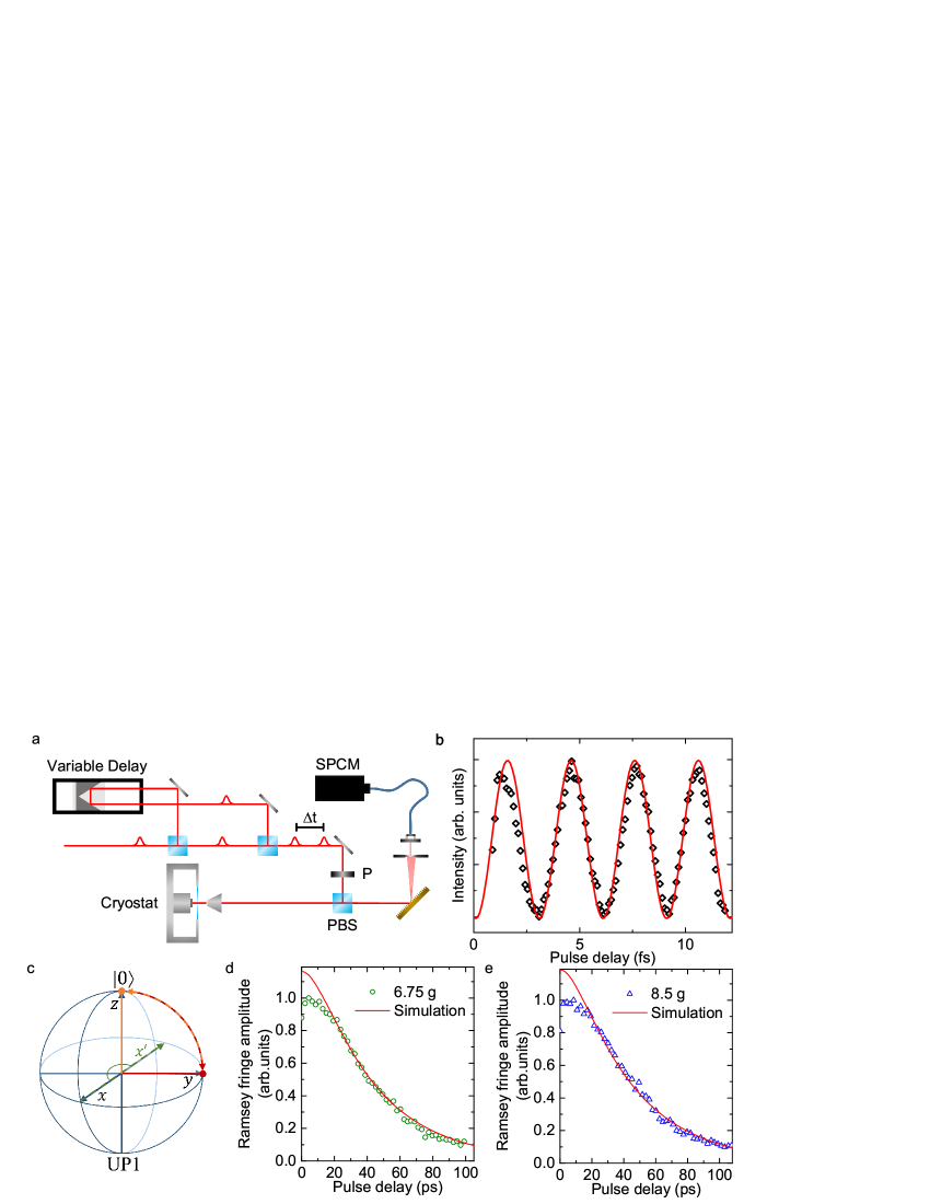
From the Rabi oscillations in figure 1c, the excitation power for each arm of the delay line is carefully chosen to be . Typical results of such a two-pulse experiment are presented in figure 2b. Here, the QD-cavity detuning is , while the coarse pulse separation is set to be ps and is altered in the range of fs. Clear oscillations - Ramsey fringes - are observed. The rotation of the Bloch vector is illustrated in figure 2c. Starting in the ground state, the first -pulse pivots the Bloch vector about the rotation axis , resulting in a superposition lying on the equator of the Bloch sphere (illustrated in red in figure 2c). In the rotating frame, the Bloch vector does not precess on the equator. Instead, the phase difference of the two excitation pulses introduces a second rotation axis (green dashed line in figure 2c). Finally, the second -pulse pivots the Bloch vector about , which is either towards the ground state (as shown in orange in figure 2c) or towards the excited state, depending on the phase difference of the two pulses. Thus, the final state is strongly dependent on the pulse separation. This dependence can be monitored by detecting the emission from the excited state. After the arrival of the second excitation pulse, the system can end up in the excited state corresponding to the maxima in the Ramsey fringes, the ground state corresponding to the minima (as illustrated in figure 2c), or states in between.
To simulate this experiment, we take the measured polariton lifetime ( ps at ) 17, the damping parameters obtained for the Rabi oscillations (presented above) and the alternated pulse separation into account. Then we calculate the population probability of the excited state. The results are presented in figure 2b as a red line and show good agreement with the measured emission from LP1.
In order to experimentally determine the dephasing time of our system, we repeat the Ramsey fringe measurements for coarse pulse separations from ps to ps. The evolution of the fringe amplitudes with increasing pulse separation for QD-cavity detunings of and are shown in figures 2d and 2e, respectively.
We extract the dephasing times by fitting the data with an exponential decay function, resulting in ps and ps, respectively.
Using the same model as in figure 2b and the experimentally obtained polariton lifetimes of ps () and ps ()17, we can reproduce the measured data in simulations. The results are presented as red solid lines in figures 2d and 2e, showing good agreement. Our simulations reveal that the dephasing time is mainly limited by an excitation power-dependent and a phonon-induced dephasing 38, 39. Only for small delay times, the measured amplitudes are smaller than the simulated ones. The mismatch for small pulse separations between data and simulation may result from the interference of the excitation pulses when they overlap in time. Although the model takes this into account, it is not perfectly consistent with the data, probably due to the experimentally limited stability of the phase, which is extremely sensitive when the pulses overlap.
Complete Coherent Control
We now turn our attention to complete coherent control of the polariton on the Bloch sphere. To this end, we perform experiments in which we vary both, the excitation power and phase difference in a two-pulse experiment.
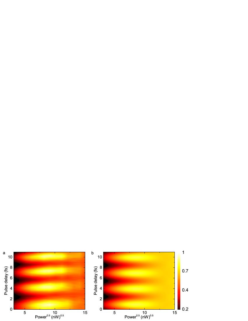
In figure 3a we present the measured emission from LP1 under resonant excitation of UP1 with two pulses. The pulse separation in this measurement is set to ps and altered by fs, while the excitation pulse powers are independently increased.
The data clearly reveals first-order maxima at an excitation power of per pulse, followed by minima at an excitation power of per pulse. We note here that resolving the second-order maxima with sufficient contrast is extremely difficult, since the strong power-dependent damping resulting from the polariton-phonon coupling increases with the laser power. This effect originates from the hybridization of the polariton levels. With increasing excitation power higher rungs start to mix with UP1, opening up channels for more phonon interaction within the system 17. Another effect reducing the visibility of the second-order maxima is a very small sample drift in the He flow cryostat during the long measurement time of min and longer. Due to this drift, the effect of the sensitive technique SHS is reduced. In addition to that, the excitation and the detection efficiency suffer from the drift.
Again, we can explain the experiment in the Bloch sphere picture: Depending on the excitation power, the first pulse will rotate the Bloch vector to a corresponding superposition of ground and excited state. Thus, using the phase difference between the pulses, the second pulse can rotate the Bloch vector across the sphere and we can access any point on the Bloch sphere by varying the excitation power.
For our experimental results this means that complete coherent control is successfully demonstrated. The whole Bloch sphere can be accessed with an excitation power of per pulse, which corresponds to the first-order minima in the complete coherent control measurements.
Our simulations with the quantum optical model that already show good agreement for Rabi oscillations and Ramsey fringes support our experimental findings and are presented in figure 3b.
Conclusion
In this work, we investigate the possibility to perform coherent optical control of a QD strongly coupled to a photonic crystal cavity. The strong exciton-phonon interaction within the system facilitates a population transfer from the upper to the lower polariton, which significantly increases the emission rates and allows for sophisticated excitation-detection schemes. Using a cross-polarized setup combined with spectral filtering and self-homodyne 34 suppression allows us to infer the population of the polariton state after the interaction with one or two short optical pulses.
With the observation of Rabi oscillations, we provide fundamental confirmation of the coherent interaction between the laser and a polaritonic state. Moreover, the successful demonstrations of Ramsey fringes and finally complete coherent control provide evidence that on-chip integrated photonic crystal cavity polariton-based quantum optical systems can be controlled. Compared to QDs alone, we can benefit from all advantages of the QD-photonic crystal cavity system, such as the efficient photonic interface 9, 15, 23, 40, 41 and unprecedented fast emission rates in non-classical light generation 17, while retaining full access to the Bloch sphere.
To support, understand and interpret the experimental results, we also developed a phenomenological quantum optical model, which produces good overall agreement with the measurements. We find significant phonon-induced dephasing, which comes along with a population transfer from UP1 to LP1, facilitating single photon emission from LP1 17 and indistinguishable photon generation at elevated temperature and unprecedented fast emission rates from UP1 15. This interaction also has a strong influence on the excitation conditions for high-fidelity photon blockade 16, 17. In particular, the phonon interaction shortens the lifetime of the polaritons and shorter excitation pulse lengths are required to reach the lowest second order coherence values. Combining our demonstration of coherent control with efficient coupling to waveguides 42, would make strongly coupled QD-photonic crystal cavity systems viable candidates for non-classical on-chip photonic devices.
Methods
Sample fabrication
The MBE-grown structure consists of an nm thick sacrificial layer followed by a nm thick GaAs layer containing a single layer of InAs QDs. Our growth conditions result in a typical QD density of . Using keV e-beam lithography with ZEP resist, followed by reactive ion etching and HF removal of the sacrificial layer, we define the photonic crystal cavity. The photonic crystal lattice constant was nm and the hole radius nm. The cavity fabricated is a linear three-hole defect (L3) cavity. To improve the cavity quality factor, holes adjacent to the cavity were shifted.
Optical spectroscopy
All optical measurements were performed with a liquid helium flow cryostat at temperatures in the range K. For excitation and detection, a microscope objective with a numeric aperture of was used. Cross-polarized measurements were performed using a polarizing beam splitter. To further enhance the extinction ratio, additional thin film linear polarizers were placed in the excitation/detection pathways and a single mode fibre was used to spatially filter the detection signal. Furthermore, two waveplates were placed between the beamsplitter and microscope objective: a half-wave plate to rotate the polarization relative to the cavity and a quarter-wave plate to correct for birefringence of the optics and sample itself. Photons are detected after spectral filtering with a single photon avalanche diode.
The thin film polarizers and polarizing beamsplitters allow us to achieve an extinction ratio of between excitation and detection path on bulk. This suppression ratio is large enough such that light geometrically rotated by the high NA objective plays little role in the ultimate laser suppression. Instead, the amount of light classically scattered into the detection channel is determined by the fidelity of the self-homodyne effect. Experimentally, we previously found that this effect was capable of interferometrically cancelling of the light scattered through the L3 cavity’s fundamental mode 34. In light of this strong suppression, no background has been subtracted from the experimental data.
Throughout the measurements we use a picosecond pulsed laser with MHz repetition rate with -ps laser pulses. We use a 4f pulse shaper with an lines/mm grating and a cm lens to create ps long pulses.
Simulations
The simulations in this paper are performed using the Quantum Toolkit in PYTHON (QuTiP) 37. The model contains of a two level system described by the Hamiltonian , where
| (3) |
is the unperturbed term in the rotating frame with the ground state frequency , the eigenfrequency of the system and the frequency of the excitation laser . While the driving term is given by
| (4) |
with excitation power . The model includes excitation with either one excitation pulse for Rabi oscillations or with two laser pulses with a pulse separation of , introducing a phase shift, for Ramsey fringes and complete coherent control. For all experiments the evolution of the population of the excited state is calculated with respect to the time. In order to do so, the evolution of the density matrix is calculated in the rotating frame
| (5) |
and we numerically integrated equation 5. Each collapse operator is included in the model as a Lindblad superoperator . The collapse operators used are: The radiative decay
| (6) |
with the detuning dependent radiative decay rate , the phonon dephasing
| (7) |
with a phonon dephasing rate of , and a dephasing term that depends on the excitation power
| (8) |
with the fitting parameter . This sum of population directly corresponds to the photon emission of the system 43 and produces good agreement to all experiments presented throughout this paper.
References
- 1 Monroe, C., Quantum information processing with atoms and photons. Nature 416, 238–246 (2002).
- 2 Vučković, J. & Yamamoto, Y., Photonic crystal microcavities for cavity quantum electrodynamics with a single quantum dot. Appl. Phys. Lett. 82, 2374 (2003).
- 3 Jelezko, F. & Wachtrup, J., Single defect centres in diamond: A review. Phys. Status Solidi (A) 203, 3207–3225 (2006).
- 4 Michler, P., Single Semiconductor Quantum Dots. Springer, (2009).
- 5 Mas-Balleste, R., Gomez-Navarro, C., Gomez-Herrero, J. & Zamora, F., 2D materials: to graphene and beyond. R. Soc. Chem. Adv. 3, 20–30 (2011).
- 6 Stievater, T.H., et al., Rabi Oscillations of Excitons in Single Quantum Dots. Phys. Rev. Lett. 87, 133603 (2001).
- 7 Zrenner, A., et al., Coherent properties of a two-level system based on a quantum-dot photodiode. Nature 418, 612–614 (2002).
- 8 Ramsay, A.J., A review of the coherent optical control of the exciton and spin states of semiconductor quantum dots. Semicond. Sci. Technol. 25, 103001 (2010).
- 9 Englund, D., et al., Controlling the Spontaneous Emission Rate of Single Quantum Dots in a 2D Photonic Crystal. Phys. Rev. Lett. 95, 013904 (2005).
- 10 Brossard, F.S.F., et al., Strongly coupled single quantum dot in a photonic crystal waveguide cavity. Appl. Phys. Lett. 97, 111101 (2010).
- 11 Reinhard, A., et al., Strongly correlated photons on a chip. Nature Photon. 6, 93–96 (2011).
- 12 Kim, H., Bose, R., Shen, T., Solomon, G. & Waks, E., A quantum logic gate between a solid-state quantum bit and a photon. Nature Photon. 7, 373–377 (2013).
- 13 Lodahl, P., et al., Controlling the dynamics of spontaneous emission from quantum dots by photonic crystals. Nature 430, 654–657 (2004).
- 14 Wilson-Rae, I. & Imamoglu, A., Quantum dot cavity-QED in the presence of strong electron-phonon interactions. Phys. Rev. B 65, 235311 (2002).
- 15 Müller, K., et al., Nanocavity-enabled ultrafast generation of highly-indistinguishable photons. arXiv preprint, arXiv:1512.05626 (2015).
- 16 Müller, K., et al., Coherent Generation of Nonclassical Light on Chip via Detuned Photon Blockade. Phys. Rev. Lett. 114, 233601 (2015).
- 17 Müller, K., et al., Ultrafast Polariton-Phonon Dynamics of Strongly Coupled Quantum Dot-Nanocavity Systems. Phys. Rev. X 5, 031006 (2015).
- 18 Sun, S., Kim, H., Solomon, G.S. & Waks, E., A quantum phase switch between a single solid-state spin and a photon. Nat. Nano., DOI:10.1038/nnano.2015.334 (2016).
- 19 Blattmann, R., Krenner, H.J., Kohler, S. & Hänggi, P., Entanglement creation in a quantum-dot-nanocavity system by Fourier-synthesized acoustic pulses. Phys. Rev. A 89, 012327 (2014).
- 20 Clark, S.M., Fu, K.M.C., Ladd, T.D. & Yamamoto, Y., Quantum computers based on electron spins controlled by ultrafast off-resonant single optical pulses. Phys. Rev. Lett. 99, 040501 (2007).
- 21 Akahane, Y., Asano, T., Song, B.-S.S. & Noda, S., High-Q photonic nanocavity in a two-dimensional photonic crystal. Nature 425, 944–947 (2003).
- 22 Arakawa, Y., Iwamoto, S., Nomura, M., Tandaechanurat, A. & Ota, Y., Cavity Quantum Electrodynamics and Lasing Oscillation in Single Quantum Dot-Photonic Crystal Nanocavity Coupled Systems. IEEE J. Sel. Top. Quantum Electron. 18, 1818–1829 (2012).
- 23 Hennessy, K., et al., Quantum nature of a strongly coupled single quantum dot-cavity system. Nature 445, 896–899 (2007).
- 24 Jaynes, E.T. & Cummings, F.W., Comparison of quantum and semiclassical radiation theories with application to the beam maser. Proc. IEEE 51, 89–109 (1963).
- 25 Laussy, F.P., del Valle, E., Schrapp, M., Laucht, A. & Finley, J.J., Climbing the Jaynes-Cummings ladder by photon counting. J. Nanophotonics 6, 061803 (2012).
- 26 Reithmaier, J.P., et al., Strong coupling in a single quantum dot-semiconductor microcavity system. Nature 432, 197–200 (2004).
- 27 Peter, E., et al., Exciton-Photon Strong-Coupling Regime for a Single Quantum Dot Embedded in a Microcavity. Phys. Rev. Lett. 95, 067401 (2005).
- 28 Englund, D., et al., Controlling cavity reflectivity with a single quantum dot. Nature 450, 857–861 (2007).
- 29 Kaniber, M., et al., Tunable single quantum dot nanocavities for cavity QED experiments. J. Phys. Condens. Matter 20, 454209 (2008).
- 30 Kaniber, M., et al., Highly efficient single-photon emission from single quantum dots within a two-dimensional photonic band-gap. Phys. Rev. B 77, 073312 (2008).
- 31 Gaudreau, L., et al., Coherent control of three-spin states in a triple quantum dot. Nat. Phys. 8, 54–58 (2011).
- 32 Webster, L.A., et al., Coherent Control to Prepare an InAs Quantum Dot for Spin-Photon Entanglement. Phys. Rev. Lett. 112, 126801 (2014).
- 33 Dominici, L., et al., Ultrafast Control and Rabi Oscillations of Polaritons. Phys. Rev. Lett. 113, 226401 (2014).
- 34 Fischer, K.A., et al., Self-homodyne measurement of a dynamic Mollow triplet in the solid state. Nature Photon., DOI:10.1038/nphoton.2015.276 (2016).
- 35 Ota, Y., Iwamoto, S., Kumagai, N. & Arakawa, Y., Impact of interactions on quantum-dot cavity quantum electrodynamics. arXiv preprint, arXiv:0908.0788 (2009).
- 36 Hohenester, U., et al., Phonon-assisted transitions from quantum dot excitons to cavity photons. Phys. Rev. B 80, 201311 (2009).
- 37 Johansson, J.R., Nation, P.D. & Nori, F., QuTiP 2: A Python framework for the dynamics of open quantum systems. Comput. Phys. Commun. 184, 1234–1240 (2013).
- 38 Ramsay, A.J., et al., Damping of Exciton Rabi Rotations by Acoustic Phonons in Optically Excited InGaAs/GaAs Quantum Dots. Phys. Rev. Lett. 104, 017402 (2010).
- 39 Ramsay, A.J., et al., Phonon-Induced Rabi-Frequency Renormalization of Optically Driven Single InGaAs/GaAs Quantum Dots. Phys. Rev. Lett. 105, 177402 (2010).
- 40 Laurent, S., et al., Indistinguishable single photons from a single-quantum dot in a two-dimensional photonic crystal cavity. Appl. Phys. Lett. 87, 163107 (2005).
- 41 Majumdar, A., Rundquist, A., Bajcsy, M. & Vučković, J., Cavity quantum electrodynamics with a single quantum dot coupled to a photonic molecule. Phys. Rev. B 86, 045315 (2012).
- 42 Faraon, A., Waks, E., Englund, D., Fushman, I. & Vučković, J., Efficient photonic crystal cavity-waveguide couplers . Appl. Phys. Lett. 90, 073102 (2007).
- 43 Kaer, P., Nielsen, T.R.R., Lodahl, P., Jauho, A.P. & Mø rk, J., Microscopic theory of phonon-induced effects on semiconductor quantum dot decay dynamics in cavity QED. Phys. Rev. B 86, 085302 (2012).
Acknowledgements
We gratefully acknowledge financial support from the Air Force Office of Scientific Research, MURI center for multifunctional light-matter interfaces based on atoms and solids (Grant No. FA9550-12-1-0025) and support from the Army Research Office (Grant No. W911NF1310309). KAF acknowledges support from the Lu Stanford Graduate Fellowship and the National Defense Science and Engineering Graduate Fellowship. KM acknowledges support from the Alexander von Humboldt Foundation. KGL acknowledges support from the Swiss National Science Foundation. JLZ acknowledges support from the Stanford Graduate Fellowship. YK acknowledges support from the Stanford Graduate Fellowship and the National Defense Science and Engineering Graduate Fellowship.
Author contributions statement
CD, KM and KGL performed the experiments. TS performed the MBE growth of the QD structure. AR and TS fabricated the photonic crystal device. CD and KAF performed the theoretical work and simulations. JLZ and YK provided expertise. JV supervised the entire project. All authors contributed to discussions and writing the manuscript.
Competing financial interests
The authors declare no competing financial interests.